Table of Contents
Advertisement
—
D I S T R I B U T I O N S O L U T I O N S
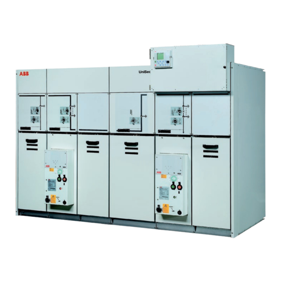
UniSec
Installation manual
Index
Safety
Introduction
1. Product information
1.1 Unit dimensions
1.2 Weights
2. Transport and storage
2.1 Condition on delivery
2.2 Unpacking at installation site
2.3 Handling the units as far
as the installation site
2.4 Temporary storage
2.5 Delivery responsibilities
3. Assembly of the switchgear on site
3.1 General warnings and cautions
3.2 Preparations
3.3 Dimensional foundation drawings
3.4 Foundations
3.5 Installation procedure for units
3.6 Gas vent ducts
3.7 Coupling to panels with withdrawable
circuit-breaker and switch-disconnector
(GSec)
4. Cable connections
4.1 Installing the cables
4.2 Control cables
4.3 Earthing the switchgear
4.4 Final installation work
A. Tightening torques for steel screws and
nuts/bolts
B. Tools required for installation
2
3
4
4
7
8
8
8
9
11
12
13
13
13
13
23
23
34
38
39
39
45
45
46
47
51
Advertisement
Table of Contents

Related Manuals for ABB UniSec SDS


Summary of Contents for ABB UniSec SDS
- Page 1 — D I S T R I B U T I O N S O L U T I O N S UniSec Installation manual Index Safety Introduction 1. Product information 1.1 Unit dimensions 1.2 Weights 2. Transport and storage 2.1 Condition on delivery 2.2 Unpacking at installation site 2.3 Handling the units as far as the installation site 2.4 Temporary storage...
-
Page 2: For Your Safety
Always follow the instructions in the manual and with all the relevant IEC safety regulations and those respect the rules of good engineering practice of other technical authorities, also respecting other (GEP)! Hazardous voltages can cause serious injury overriding instructions. It is recommended that ABB or death! Disconnect the power and earth live service personnel be called in to perform the parts before proceeding with any work on the servicing and repair work. -
Page 3: General Aspects
D I S T R I B U T I O N S O LU T I O N S — Introduction General aspects UniSec is an air-insulated switchgear for indoor use, designed for medium voltage secondary distribution. UniSec switchgear is the result of continuous innovation, following the desire to meet ever-changing market needs. This new series of switchgear offers a wide range of long-term technical solutions. Safety, reliability, user-friendliness and simplicity of installation, as well environmental sustainability were the driving forces in developing this switchgear. UniSec is structured by placing standardized units side by side in a coordinated way. Construction and testing are carried out in the factory. Installation manual This manual provides information on installation of UniSec units. It contains details about product dimensions and weights, as well as instructions for... -
Page 4: Product Information
U N I S E C I N S TA L L AT I O N M A N U A L — 1. Product information 1.1 Unit dimensions Code Description Width 190 mm 375 mm 500 mm 600 mm 750 mm •... - Page 5 D I S T R I B U T I O N S O LU T I O N S Side view of the different LSC2A units 1070 1070 Figure 3. Side view IAC A-FL 12.5 kA, with filters Figure 4. Side view IAC A-FLR 16 kA, with filters Side view of the different LSC2B units DRS for WBS 1070...
- Page 6 U N I S E C I N S TA L L AT I O N M A N U A L — 1. Product information Side view of the different LSC2B units DRS for WBS 1200/1300 1200/1300 Figure 7. Side view for panels with withdrawable circuit-breakers, Figure 8.
-
Page 7: Weights
D I S T R I B U T I O N S O LU T I O N S 1.2 Weights The following table shows the maximum weights of the different units. Weights are indicative, without CTs, VTs and fuses. For further information please contact ABB. Unit Panel width Panel width 1700 mm 2000 mm 150 160 170 180 195... -
Page 8: Transport And Storage
U N I S E C I N S TA L L AT I O N M A N U A L — 2. Transport and storage Unpacking 2.1 Condition on delivery The UniSec units are fixed to the pallet using Delivery packing separate fixing plates (2 plates on the back of the UniSec is delivered either as a single unit or in unit) and bolts (2 bolts on the front of the unit) multiple switchgear units with a length of no more inside the unit. than 2.0 m, and with the doors closed. The size of the pack(s) depends on the number and type of units and a) Remove the plastic film from the units. has to be defined separately in each case. -
Page 9: Handling The Units As Far As The Installation Site
D I S T R I B U T I O N S O LU T I O N S 2.3 Handling the units as far as the installation site 2.3.1 General warnings and cautions DANGER Only carry out loading operations when it has been ensured that all precautionary measures to protect personnel and materials have been taken Figure 12. - Page 10 U N I S E C I N S TA L L AT I O N M A N U A L — 2. Transport and storage Operations to be carried out before lifting a) Install the lifting hooks on the roof frame. Figure 16. Figure 19. Roof frame + lifting hooks If a crane is available, lifting can be done by using the lifting hooks which are delivered separately. The lifting procedure, including how to install the lifting...
-
Page 11: Temporary Storage
The duration of the protective effect of the packing when lifting several units or a whole switchgear (4 is limited to a few months when stored indoors in a units at the most, or a maximum length of 2 m). dry place. ABB should be consulted in the case of longer storage periods or if the storage conditions Lifting by crane differ from those indicated 2.4.2 Optimum storage conditions... -
Page 12: Delivery Responsibilities
U N I S E C I N S TA L L AT I O N M A N U A L Type of packing 2.5 Delivery responsibilities Special instructions depending on the type of packing are given below: Responsibilities The responsibilities of the consignee when the 1. Units with basic packing or without packing switchgear arrives on site include, but are not 1) Use a dry, well-ventilated place with climatic limited to, the following:... -
Page 13: General Warnings And Cautions
3.1 General warnings and cautions 3.2 Preparations Before starting To commence installation on site, the switchgear room must be absolutely suitable, i.e. provided with WARNING lighting and electricity, fitted with a padlock, Once the documents have been prepared for final ventilation facilities and must also be dry. mounting, the binding data supplied by ABB must All the necessary preparations, such as wall always be taken into account! openings, ducts, etc. for laying the power and control cables as far as the switchgear, must already have been completed. Before proceeding with installation: WARNING a) Clean the installation site... - Page 14 U N I S E C I N S TA L L AT I O N M A N U A L — 3. Assembly of the switchgear on site Installation room The installation room must be prepared to suit the size and version of the switchgear. Compliance with the distances indicated will ensure that the equipment functions correctly and safely. Consult ABB if the installation conditions differ from those indicated. Room layout IAC A-FL 12.5 kA, 1sec against a wall IAC A-F 16 kA 1070 1000 min 1070 1000 min Figure 25.
- Page 15 D I S T R I B U T I O N S O LU T I O N S Room layout IAC A-FL 12.5 kA filters IAC A-FLR 16 kA against a wall 200 min 1070 1000 min 200 min 1070 1000 min Figure 27.
- Page 16 IAC A-FLR 21 kA 1s with filters installed on each unit solution IAC A-FLR 21/25(2) kA 1s with gas exhaust ducts ATTENTION IAC A-FLR version – No access limitations to the Swg Room. Installation distances to be respected (*) 1300 mm at least, for panels with circuit-breaker (1) For special conditions defined by ABB, the minimum distance can be up to 130 mm (2) Only for 12 kV LSC2A units, height 2000 mm and width 750 mm (except for units SBC-W, SBS-W, SDD, UMP and SBR)
- Page 17 Figure 32. Minimum distances from the walls of the installation room, for units SBC-W, SBS-W, SDD, UMP and SBR) solution IAC A-FLR 25 kA, 1s @ 12-17.5 and 16 kA, 1s @ 24 kV with filters installed on each unit (*) 1300 mm at least, for panels with circuit-breaker (1) For special conditions defined by ABB, the minimum distance can be up to 130 mm (2) Only for 12 kV LSC2A units, height 2000 mm and width 750 mm (except for units SBC-W, SBS-W, SDD, UMP and SBR)
- Page 18 Figure 34. Minimum distances from walls of installation room, solution IAC A-FLR 25 kA, 1s @ 12-17.5 and 21 kA, 1s @ 24 kV solution IAC A-FL 12.5 kA 1s with filters installed with gas exhaust ducts on each individual unit (1) For special conditions defined by ABB, the inimum distance can be up to 130 mm (2) In the case of special conditions, contact ABB for the minimum distances required...
- Page 19 D I S T R I B U T I O N S O LU T I O N S 3.3.2 Cable passage hole dimensions and fixing points The following figures show the locations and sizes of the cable passage holes under the different units. These holes must be made before installation of the switchgear. The figures also show the switchgear fixing points. There is one fixing point in each corner of the unit (4 per unit). Units without cable entry have dimensions and fixing points according to the width of the unit 10 mm anchoring bolts can be used for fixing. — — 375 mm wide units Width 500 mm for DRC unit Ø12,5 Ø12,5...
- Page 20 U N I S E C I N S TA L L AT I O N M A N U A L — 3. Assembly of the switchgear on site — — — DRC/W units 750 mm wide units 190 mm width for RLC/RRC units 43,5 43,5 Ø12,5 Ø12,5...
- Page 21 D I S T R I B U T I O N S O LU T I O N S 3.3.3 Medium voltage cable locations and lengths The medium voltage cable lengths (distance of the The following figures and table show the cable cable connection point from the floor) depend on lengths and locations for the different units. the units and accessories used. RLC unit — Medium voltage cable lengths and locations 190 mm width 375 mm width 500 mm width...
- Page 22 U N I S E C I N S TA L L AT I O N M A N U A L — 3. Assembly of the switchgear on site LSC2B units LSC2B unit (front) LSC2B unit (side) — Lunghezze e posizioni dei cavi di media tensione 600 mm width 750 mm width Details A (mm)
-
Page 23: Installation Procedure For Units
D I S T R I B U T I O N S O LU T I O N S 3.4 Foundations 3.4.1 Foundation types General aspects The switchgear must be erected on a foundation that fulfils the requirement of a 2 mm maximum horizontal height deviation in relation to the length and diagonal of the switchgear. These calculations must be made by technically qualified personnel. Figure 39. 500 mm wide units 3.5 Installation procedure for units 3.5.2.2 Top plate removal from BIG compartments 3.5.1 Assembly of the first two switchgear units The plate is removed in the following way:... - Page 24 U N I S E C I N S TA L L AT I O N M A N U A L — 3. Assembly of the switchgear on site b) Screw the joining plate and the unit plates together (with 6 Torx M6x12 screws) so that they are fully tightened. Insert a bolt (M8x20 round- headed with square neck) with a nut (M8 hexagonal nut with flange) (figure 45) to tighten the units and the joining plate. Figure 42. c) Lift and remove the plate. Figure 45. Screws for the top joining plate Figure 43.
- Page 25 D I S T R I B U T I O N S O LU T I O N S NOTE Do not remove ceiling frame in the case of functional units with roof applications and SBR units f) For WBC and WBS units, insert 6 hexagonal bolts with the relative nuts. Figure 47.
- Page 26 U N I S E C I N S TA L L AT I O N M A N U A L — 3. Assembly of the switchgear on site Raised panel position The busbar connections are made through the top 1) The raised position can be used when cable openings raceways cannot be created. a) Clean and scrape the busbar connections. 2) This does not obstruct the activities of the b) Clean the insulation of the busbar sections with a substation.
- Page 27 D I S T R I B U T I O N S O LU T I O N S The following figures show the busbar connections for units with switch-disconnector. The components required are indicated in Table 5. The main busbar connections of each unit type with different rated currents and voltages are shown. Each figure gives a reference to the corresponding numbers of the components in Table 5. All unit types, list of components used All unit types, list of components used Part Name Part...
- Page 28 U N I S E C I N S TA L L AT I O N M A N U A L — 3. Assembly of the switchgear on site Units with 12-17.5 kV, 630-800 A switch-disconnector Units with 24 kV, 630 A switch-disconnector Units with 12-17.5 kV, 1250 A switch-disconnector...
- Page 29 D I S T R I B U T I O N S O LU T I O N S DRS/DRC end or isolating units For DRC and DRS units, the busbars are not installed Therefore to tighten the screws properly, the nuts directly on the top of the switch-disconnector or must be installed under the busbars. bushing. DRS/DRC 12-17.5 kV, 630-800 A end or isolating units DRS/DRC 24 kV, 630 A end or isolating units DRS/DRC 12-17.5 kV, 1250 A end or isolating units...
- Page 30 U N I S E C I N S TA L L AT I O N M A N U A L — 3. Assembly of the switchgear on site For the SBR unit up to 24 kV, 630 A - Units with insulators Busbar exit on the left Busbar exit on the right Units with current transformers and Combisensors Busbar exit on the left...
- Page 31 D I S T R I B U T I O N S O LU T I O N S WBC - WBS, 630 A middle unit WBC - WBS, 1250 A middle unit 630 A middle unit 1250 A middle unit WBC - WBS, 630 A end unit WBC - WBS, 1250 A end unit 630 A end unit...
- Page 32 U N I S E C I N S TA L L AT I O N M A N U A L — 3. Assembly of the switchgear on site Panel for coupling unit with WBC – WBS to unit with 12-17.5 kV, 630 A switch-disconnector 12-17.5 kV, 630 A middle unit 12-17.5 kV, 630 A end unit Panel for coupling unit with WBC –...
- Page 33 D I S T R I B U T I O N S O LU T I O N S Connection between SBS and DRC units 3.5.7 Reinstallazione delle piastre del tetto L’installazione prevede le seguenti operazioni: 1) Installare la piastra tetto. 2) Rimontare le viti staccate durante la procedura di smontaggio. 3) Per le unità terminali e di sezionamento: Installare la doppia piastra del tetto. Non è necessario avvitare le piastre (solo per la versione IAC 21 kA 1s).
-
Page 34: Gas Vent Ducts
U N I S E C I N S TA L L AT I O N M A N U A L — 3. Assembly of the switchgear on site c) Screw 3 additional screws (Torx M6x12) in the 3.6 Gas vent ducts bottom plate as shown in Figure 75. 3.6.1 Installation of the gas vent ducts The gas vent ducts are usually already installed. a) Install the vertical part of the gas vent duct. Figure 75. - Page 35 D I S T R I B U T I O N S O LU T I O N S Figure 79. Connected gas vent duct; additional duct and end plate Connecting these parts can be done in the same way Figure 77. Installed gas vent duct as in the previous stages. An additional duct is used in the end unit to direct any gas due to arc faults out of the switchgear room.
- Page 36 U N I S E C I N S TA L L AT I O N M A N U A L — 3. Assembly of the switchgear on site Figure 81. Side view Figure 83. Side view Example of raised lateral gas outlet Example of rear outlet Figure 84.
- Page 37 D I S T R I B U T I O N S O LU T I O N S Example of raised rear outlet 3.6.3 Gas exhaust filters 16 kA - Version BE Rear Rear closing closing Figure 86. Side view Figure 87.
- Page 38 The available adapter panels are: 3.7 Coupling to panels with Width Weight withdrawable circuit-breaker Unit (mm) (kg) and switch-disconnector (GSec) SBC The different design of the panels WBC/WBS/BME and the different height of the omnibus busbars not allowed direct coupling with the panels with switch- Estimated weight, considering the base unit with 630 A busbars, without disconnector and/or removable circuit breaker both TA, TV and fuses Can be coupled only on the left side of WBC/WBS/BME units with H = 1700 mm and H = 2000 mm. withdrawable circuit-breakers Adapter panels have been created for this type of An adapter panel allowing UniSec switchgear to be compartment so as to allow the busbars to be coupled to the other ABB switchgear (UniMix and connected. The height of the adapter panel is 2000 mm. UniSwitch) is available on request. The adapter panel keeps all the characteristics of a standard panel and can therefore be used as an incoming/outgoing unit. LSC2B LSC2A LSC2A Figure 89.
-
Page 39: Cable Connections
D I S T R I B U T I O N S O LU T I O N S — 4. Cable connections Operations 4.1 Installing the cables 1. Dismantle the cable clamps, cable guide splines, fairleads and the floor sheet a) Unscrew the eight bolts on the floor and remove the bottom plates. NOTE The position of the medium voltage cables are positioned L1, L2 and L3 front to back 4.1.1 Installing the cables Parts... - Page 40 U N I S E C I N S TA L L AT I O N M A N U A L — 4. Cable connections c) Prepare the cable insulating ends and mount them on the cable cores according to the manufacturer’s instructions. NOTE d) C onnect the cables to the cable terminals as In the case of a circuit-breaker, fit the floor plates shown in Figure 94.
- Page 41 D I S T R I B U T I O N S O LU T I O N S 1) Unscrew at the top of the RLC front cover, lift it and remove the front RLC cover. NOTE Tighten to the correct torque! See the tightening torques table at the end of the manual! Figure 100. RLC front cover Figure 98.
- Page 42 U N I S E C I N S TA L L AT I O N M A N U A L — 4. Cable connections Connect the MV cables. 1) Cut the cable glands at the bottom of the RLC unit according to the cable diameter and fix the cables in the centre of the RLC unit to the locking part. Figure 102. RLC transversal part 4) Unscrew, lift and remove the cable Figure 104. RLC unit cable locking parts protection sheet of the RLC unit.
- Page 43 D I S T R I B U T I O N S O LU T I O N S 4.1.3 Installing the WBC unit cables a) Open cable door A by unscrewing knurled screws Figure 106. Exploded drawing of the cable locking parts on the bottom of the RLC unit 2) C onnect the cables to the circuit busbar.
- Page 44 U N I S E C I N S TA L L AT I O N M A N U A L — 4. Cable connections e) Connect the MV cables H using the H1 bolts. Cable connections Panels Width Maximum Max cross quantity of section cables per of cables phase LSC2A SBC/...
-
Page 45: Control Cables
D I S T R I B U T I O N S O LU T I O N S 4.2 Control cables 4.3 Earthing the switchgear The internal cables between units are easily laid Each unit is fitted with earthing busbars that run through openings in the side walls of the auxiliary longitudinally in the lower front part of the unit. circuit compartment. These busbars must be connected together as Depending on the delivery times, there are two shown in chapter 5.3.1. The station earthing system different procedures for supplying the connection must be connected to the end unit of the cables of the units: switchgear. If the switchgear consists of more than • Cables not included 8 units, it is advisable to connect the station •... -
Page 46: Final Installation Work
U N I S E C I N S TA L L AT I O N M A N U A L — 4. Cable connections c) Earthing busbar installed. NOTE Tightening must be carried out with the correct torque 4.3.2 Main earthing circuit connections between the panels of the SBR functional unit a) Install the protection busbar conductor between panels of the SBR functional unit. -
Page 47: A. Tightening Torques For Steel Screws And Nuts/Bolts
D I S T R I B U T I O N S O LU T I O N S — A. Tightening torques for steel screws and nuts/bolts — Nuts and bolts Max. tightening torque [Nm] Type Steel class 8.8 — Cheese-head socket screws Max. tightening torque [Nm] Type Steel class 8.8 —... - Page 48 U N I S E C I N S TA L L AT I O N M A N U A L — A. Tightening torques for steel screws and nuts/bolts — Bolts mounted on the CT, TPU type Joint type Tightening torque [Nm] min. nominal max. —...
- Page 49 D I S T R I B U T I O N S O LU T I O N S — Bolts mounted on the circuit-breaker Joint type Tightening torque [Nm] min. nominal max. — Bolts mounted on the mandolin CT Joint type Tightening torque [Nm] min.
- Page 50 U N I S E C I N S TA L L AT I O N M A N U A L — A. Tightening torques for steel screws and nuts/bolts — Bolts for mounting CT Joint type Tightening torque [Nm] min. nominal max. — GSec and busbar Joint type Tightening torque [Nm] min.
-
Page 51: B. Tools Required For Installation
D I S T R I B U T I O N S O LU T I O N S — B. Tools required for installation Torx wrench • TX30 Torx wrench Allen wrenches • 5 mm • 6 mm • 8 mm Socket wrenches • 10 mm • 15 mm •... - Page 52 More product information: abb.com/mediumvoltage Your contact center: abb.com/contactcenters More service information: abb.com/service © Copyright 2018 ABB. All rights reserved. The data and illustrations are not binding. We reserve the right to make changes in the course of technical development of the product.