Table of Contents
Advertisement
Quick Links
Advertisement
Table of Contents

Related Manuals for ABB FIO-01


Summary of Contents for ABB FIO-01
- Page 1 ABB Drives User’s Manual Digital I/O Extension FIO-01...
- Page 3 Digital I/O Extension FIO-01 User’s Manual 3AFE68784921 Rev D EFFECTIVE: 2010-08-10 © 2010 ABB Oy. All Rights Reserved.
-
Page 5: Safety Instructions
Safety instructions Overview This chapter states the general safety instructions that must be followed when installing and operating the FIO-01 Digital I/O Extension. In addition to the safety instructions given below, read the complete safety instructions of the specific drive you are working These warnings are intended for all who work on the drive. - Page 6 Safety instructions...
-
Page 7: Table Of Contents
Overview ........... 11 The FIO-01 Digital I/O Extension module ......11 Installation . - Page 8 Table of Contents...
-
Page 9: Introduction
Intended audience The manual is intended for the people who are responsible for commissioning and using the FIO-01 Digital I/O Extension. The reader is expected to have a basic knowledge of electrical fundamentals, electrical wiring practices and how to operate the drive. -
Page 10: Product And Service Inquiries
Product and service inquiries Address any inquiries about the product to your local ABB representative, quoting the type code and serial number of the unit in question. A listing of ABB sales, support and service contacts can be found by navigating to www.abb.com/drives and selecting Sales, Support and Service network. -
Page 11: Overview
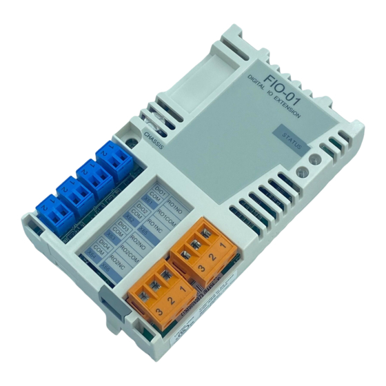
Overview Overview This chapter contains a short description of the FIO-01 Digital I/O Extension. The FIO-01 Digital I/O Extension module The FIO-01 is a general purpose digital input/output extension. It offers 4 bidirectional digital inputs/outputs and 2 electromechanical relays. FIO-01... - Page 12 Isolation areas The following figure describes the different isolation areas of the module. Connection to the drive Electromechanical relays Digital I/O X61 X62 X63 X64 CHASSIS Fixing screw The fixing screw connects the chassis to ground. Overview...
-
Page 13: Installation
Switch off all dangerous voltages connected from external control circuits to the inputs and outputs of the drive. The FIO-01 is to be inserted into the option slot of the drive. The module is held in place with plastic retaining clips and one screw. -
Page 14: Terminal Designations
Terminal designations Marking Description • DIOx = Digital I/O. Input (default), push-pull or open collector. Selection is made by parameter. See the DIO1 drive firmware manual for more information. • COM = Ground reference on option board DIO2 DIO3 DIO4 Marking Description •... -
Page 15: Wiring
Wiring The diagram presents some typical output types. Open collector Open emitter Push-pull (Sinking) (Sourcing) +24 V +24V DIOx DIOx DIOx = Digital I/O power supply voltage = Load at output channel Maximum cable size is 1.5 mm (AWG 16) for digital signals and 2.5 mm (AWG 14) for relays. -
Page 16: Programming
Programming The communication between the module and the drive is activated by a drive parameter. See the drive Firmware Manual. Note: The new settings take effect only when the module is powered up. Installation... -
Page 17: Fault Tracing
Fault tracing Diagnostic LED Colour Description Green Orange Not initialized or communication fault to control unit Power fault & not initialized or communication fault to control unit If the green LED is unlit, the digital output is short circuited. Fault tracing... - Page 18 Fault tracing...
-
Page 19: Technical Data
Technical data Dimensions 32 mm 1.26 in FIO-01 DIGITAL IO EXTENSION STATUS CHASSIS DIO1 RO1NO RO1COM DIO2 RO1NC DIO3 RO2NO RO2COM DIO4 RO2NC 63 mm 23 mm 0.91 in 2.48 in General • Max. power consumption: 350 mA at 24 V •... - Page 20 Digital I/O • All DIOs programmable as - Input (default) - Push-pull output - Open collector output • Input voltages max 30 V, reverse polarity protection • 24 V logic levels for input: “0” < 5 V, “1” > 15 V (according to standard IEC 61131-2) •...
- Page 22 ABB Oy ABB Inc. ABB Beijing Drive Systems Drives Automation Technologies Co. Ltd. P.O. Box 184 Drives & Motors No. 1, Block D, FIN-00381 HELSINKI 16250 West Glendale Drive A-10 Jiuxianqiao Beilu FINLAND New Berlin, WI 53151 Chaoyang District Telephone +358 10 22 11 Beijing, P.R.