
Related Manuals for ABB FDIO-01


Summary of Contents for ABB FDIO-01
- Page 1 Options for ABB drives, converters and inverters User’s manual FDIO-01 digital I/O extension module...
- Page 2 ACS880-1607 DC/DC converter 3AXD50000023644 units hardware manual Option manuals and guides FDIO-01 digital I/O extension 3AUA0000124966 module user’s manual You can find manuals and other product documents in PDF format on the Internet. See section Document library on the Internet on the inside of the back cover.
- Page 3 User’s manual FDIO-01 digital I/O extension module Table of contents 1. Safety instructions 4. Mechanical installation 5. Electrical installation 6. Start-up 3AUA0000124966 Rev B 2015 ABB Oy All Rights Reserved. EFFECTIVE: 2015-11-30...
-
Page 5: Table Of Contents
Table of contents 5 Table of contents 1. Safety instructions Contents of this chapter ....... . 7 Use of warnings . - Page 6 Product training ........35 Providing feedback on ABB Drives manuals ....35...
-
Page 7: Safety Instructions
Safety instructions 7 Safety instructions Contents of this chapter The chapter contains the warning symbols used in this manual and the safety instructions which you must obey when you install or connect an optional module to a drive, converter or inverter. If you ignore the safety instructions, injury, death or damage can occur. -
Page 8: Use Of Warnings
8 Safety instructions Use of warnings Warnings tell you about conditions which can cause injury or death, or damage to the equipment. They also tell you how to prevent the danger. The manual uses these warning symbols: Electricity warning tells you about hazards from electricity which can cause injury or death, or damage to the equipment. -
Page 9: Safety In Installation
Safety instructions 9 Safety in installation These instructions are for all who install or connect an optional module to a drive, converter or inverter and need to open its front cover or door to do the work. WARNING! Obey these instructions. If you ignore them, injury or death, or damage to the equipment can occur. - Page 10 10 Safety instructions...
-
Page 11: Introduction To The Manual
Introduction to the manual 11 Introduction to the manual Contents of this chapter This chapter introduces this manual. Target audience This manual is intended for people who plan the installation, install, start up, use and service the extension module. Before you do work on the module, read this manual and the applicable drive/converter/inverter manual that contains the hardware and safety instructions for the product in question. -
Page 12: Contents Of The Manual
12 Introduction to the manual Contents of the manual The manual consists of these chapters: • Safety instructions gives the safety instructions which you must obey when you install an extension module. • Hardware description gives a short description of the extension module. -
Page 13: Hardware Description
Contents of this chapter This chapter gives a short description of the extension module. Product overview The FDIO-01 digital I/O extension module expands the digital inputs and outputs of the drive control unit. It has three digital inputs and two relay outputs. -
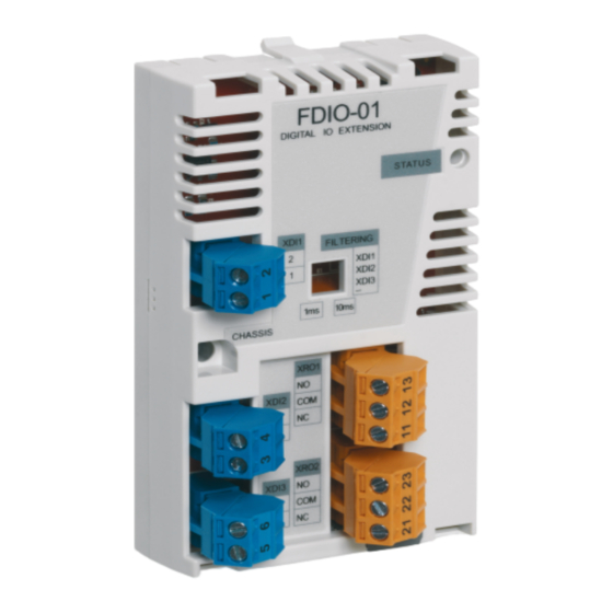
Page 14: Layout
14 Hardware description Layout XDI1 XRO1 XDI2 XRO2 XDI3... -
Page 15: Hardware Filtering For Dc Input Signals
Hardware description 15 Item Description Additional information Retaining clips Lock Page Mounting screw DIP switches for hardware filtering Page 15, XDI1 XDI2 2-pin detachable terminal blocks for digital inputs Page XDI3 XRO1 3-pin detachable terminal blocks for relay outputs Page XRO2 Diagnostic LED Page... - Page 16 16 Hardware description...
-
Page 17: Mechanical Installation
See the applicable drive hardware manual. Unpacking and examining the delivery 1. Open the option package. 2. Make sure that the package contains: • FDIO-01 digital I/O extension module • this manual. 3. Make sure that there are no signs of damage. -
Page 18: Installing The Module
18 Mechanical installation Installing the module WARNING! Obey the safety instructions. See chapter Safety instructions on page 7. If you ignore the safety instructions, injury or death can occur. …onto the drive control unit 1. Pull out the lock. 2. -
Page 19: Onto An Extension Adapter Module
Mechanical installation 19 …onto an extension adapter module For instructions on how to install the module onto an extension adapter module, see FEA-03 F-series extension adapter user’s manual (3AUA0000115811 [English]). - Page 20 20 Mechanical installation...
-
Page 21: Electrical Installation
Electrical installation 21 Electrical installation Contents of this chapter This chapter contains instructions on adjusting hardware filtering for DC input signals and wiring the extension module. Warnings WARNING! Obey the safety instructions. See chapter Safety instructions on page 7. If you ignore the safety instructions, injury or death can occur. -
Page 22: Adjusting Hardware Filtering For Dc Input Signals
22 Electrical installation Adjusting hardware filtering for DC input signals Set the DIP switches (see page 14) to the applicable positions for the necessary inputs. This table shows the possible positions for each input. Filtering DIP switch setting time XDI1 XDI2 XDI3 10 ms... -
Page 23: Terminal Designations
Electrical installation 23 Terminal designations Digital inputs Marking Description XDI1 Digital input 1 terminal 1 Digital input 1 terminal 2 XDI2 Digital input 2 terminal 3 Digital input 2 terminal 4 XDI3 Digital input 3 terminal 5 Digital input 3 terminal 6 ... -
Page 24: Wiring
24 Electrical installation Wiring Connect the external control cables to the applicable module terminals. Digital input wiring example FDIO XDIx 110…230 V AC ±10% 24…250 V DC XDIx (polarity unimportant) -
Page 25: Start-Up
Start-up 25 Start-up Contents of this chapter This chapter contains instructions on starting up the extension module. Before you start Make sure that you have completed these start-up tasks for the drive: • Checks and settings with no voltage connected •... - Page 26 26 Start-up...
-
Page 27: Diagnostics
Diagnostics 27 Diagnostics Contents of this chapter This chapter shows how to trace faults with the status LED on the extension module. Faults and warning messages For the fault and warning messages concerning the extension module, see the drive firmware manual. LEDs The extension module has one diagnostic LED. - Page 28 28 Diagnostics...
-
Page 29: Technical Data
Technical data 29 Technical data Contents of this chapter This chapter contains the technical data of the extension module. -
Page 30: Dimension Drawing
30 Technical data Dimension drawing The dimensions are in millimeters. -
Page 31: Data
Technical data 31 Data Installation Into an option slot on the drive control unit or onto an extension adapter module (FEA-03) Degree of protection IP20 Ambient conditions The applicable ambient conditions specified for the drive in its manuals are in effect. -
Page 32: Isolation Areas
32 Technical data Isolation areas Symbol Description Basic insulation (IEC 61800-5-1:2007) Digital inputs (XDI1:1…2, XDI2:3…4, XDI3:5…6) • Connector pitch 5 mm, wire size max. 2.5 mm • Torque: 0.5 N·m • Input voltages: 24…250 V DC or 110…230 V AC •... -
Page 33: Relay Outputs (Xro1:11
Technical data 33 Relay outputs (XRO1:11…13, XRO2:21…23) • Connector pitch 5 mm, wire size max. 2.5 mm • Torque: 0.5 N·m • Max. contact voltage: 120 V DC, 250 V AC • Max. contact current/power: 5 A, 24 V DC; 0.4 A, 120 V DC; 1250 VA, 250 V AC •... - Page 34 34 Technical data...
-
Page 35: Further Information
Product and service inquiries Address any inquiries about the product to your local ABB representative, quoting the type designation and serial number of the unit in question. A listing of ABB sales, support and service contacts can be found by navigating to www.abb.com/searchchannels. - Page 36 Contact us www.abb.com/drives www.abb.com/solar www.abb.com/windconverters www.abb.com/drivespartners 3AUA0000124966 Rev B (EN) 2015-11-30...