Table of Contents
Advertisement
Quick Links
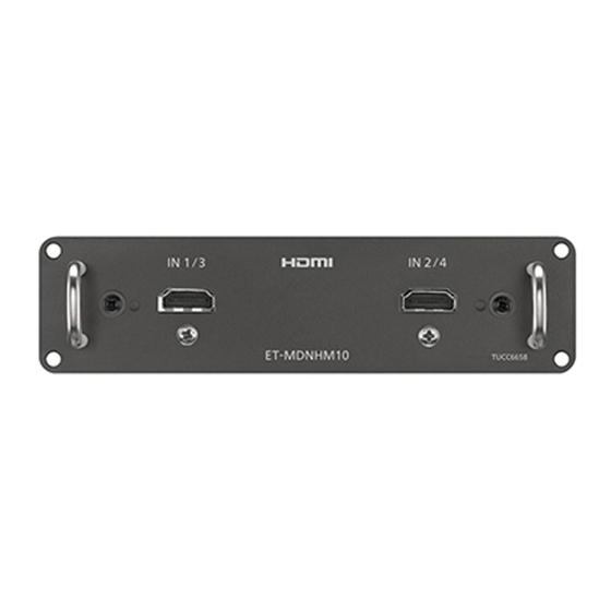
* The illustration above is an example. In this manual, illustrations of ET-MDNHM10
are used as an example unless otherwise specifi ed.
Read before use
The "Operating Instructions" explains about the interface boards to be
installed to a Panasonic display device (projector or fl at panel display).
For Model No. and model names, refer to the product list ( x page 4).
Thank you for purchasing this Panasonic product.
■ Before using this product, please read these "Operating Instructions" and
the "Operating Instructions" of the display device carefully and save the
manuals for future use.
■ Before using this product, be sure to read "Read this fi rst!" ( x page 3).
Printed in China
Operating Instructions
Interface Board
ET-MDNHM10
Model No.
ET-MDNDV10
Commercial Use
ENGLISH
FRANÇAIS
ENGLISH
TQZJ729-2
Advertisement
Table of Contents

Related Manuals for Panasonic ET-MDNHM10


Summary of Contents for Panasonic ET-MDNHM10
- Page 1 Interface Board Commercial Use ET-MDNHM10 Model No. ET-MDNDV10 * The illustration above is an example. In this manual, illustrations of ET-MDNHM10 are used as an example unless otherwise specifi ed. ENGLISH FRANÇAIS Read before use The “Operating Instructions” explains about the interface boards to be installed to a Panasonic display device (projector or fl at panel display).
-
Page 2: Table Of Contents
Contents Contents Read this first! Precautions for use Products list Supported display device About the handling of the product Disposal Accessories Part names and functions Installing the Interface Board Before installing or removing the Interface Board How to install the Interface Board How to remove the Interface Board Specifications r Trademarks... -
Page 3: Read This First
Failure to do so may cause electric shock. Importer’s name and address within the European Union Panasonic Marketing Europe GmbH Panasonic Testing Centre Winsbergring 15, 22525 Hamburg, Germany ENGLISH - 3... -
Page 4: Precautions For Use
The product names and their Model Nos. described in this document are as follows. Product name Product Model No. Remark Interface Board for HDMI An Interface Board equipped with 2 ET-MDNHM10 2 input HDMI inputs. Interface Board for DVI-D An Interface Board equipped with 2 ET-MDNDV10 2 input DVI-D inputs. -
Page 5: Disposal
Precautions for use Disposal To dispose of the product, ask your local authorities or dealer for correct methods of disposal. Accessories Make sure that the following accessories are provided with your product. Numbers enclosed in < > show the number of accessories. Screw <4>... -
Page 6: Installing The Interface Board
Installing the Interface Board r Interface Board for DVI‑D 2 input (Model No.: ET‑MDNDV10) <DVI‑D IN 1> terminal (when installed <DVI‑D IN 2> terminal (when installed in <SLOT 1> of the display device), in <SLOT 1> of the display device), <DVI‑D IN 3>... -
Page 7: How To Install The Interface Board
The figure indicating the installation and removal of the Interface Board is using the combination of the Interface Board for HDMI 2 input (Model No.: ET-MDNHM10) and the optional projector (Model No.: PT-RQ13K) as an example. Illustration of this document may vary from the actual product. -
Page 8: How To Remove The Interface Board
Installing the Interface Board How to remove the Interface Board Handle Fig. 1 Remove the Interface Board. (Fig. 1) f Remove the four screws fixing the Interface Board by rotating counterclockwise with a Phillips screwdriver. The removed screws are used to fix the slot cover. f Hold the handle of the Interface Board and remove it slowly. -
Page 9: Specifications
*1 Pixel-Repetition signal (dot clock frequency 27.0 MHz) only Note f “SLOT NX” is a name of the slot unique to Panasonic supporting the signal input for the 4K image. f The video signal that can actually display will vary depending on the display device (projector or flat panel display) that the Interface Board is installed. - Page 10 Panasonic Corporation Web Site : https://panasonic.net/cns/projector/ © Panasonic Corporation 2015 Panasonic System Solutions Company of North America Two Riverfront Plaza, Newark, NJ 07102 TEL: (877) 803 - 8492 Panasonic Canada Inc. 5770 Ambler Drive, Mississauga, Ontario L4W 2T3...