Table of Contents
Advertisement
Advertisement
Table of Contents

Related Manuals for ABB C13


Summary of Contents for ABB C13
- Page 1 User Manual...
- Page 3 User Manual Document ID: 2CMC486004M0201 Revision: B 2019-07-01...
- Page 4 ABB AB. ABB AB assumes no responsi- bility for any errors that may appear in this document. In no event shall ABB AB be liable for direct, indirect, special, incidental or con- sequential damages of any nature or kind arising from the use of this document, nor shall ABB AB be liable for incidental or consequential damages arising from use of any software or hardware described in this document.
-
Page 5: Table Of Contents
1 About this Manual ..................3 1.1 Conventions Used in this Document ................4 2 Product Overview ..................5 2.1 Meter Parts ........................6 2.2 Meter Type ........................7 3 Installation ....................9 3.1 Mounting the Meter ...................... 10 3.2 Environmental Considerations ..................11 3.3 Installing the Meter ...................... - Page 6 2CMC486004M0201 User Manual Revision: A...
-
Page 7: About This Manual
About this Manual Chapter 1: About this Manual Overview This chapter describes the conventions used in this manual. It also contains expla- nations and definitions of terms and definitions that are used in the document. In this chapter The following topics are covered in this chapter: 1.1 Conventions Used in this Document ............. -
Page 8: Conventions Used In This Document
About this Manual 1.1 Conventions Used in this Document Symbols This document contains warning, caution, note and tip icons that point out safety related conditions and other important or useful information. Symbol Description The electrical warning icon indicates the presence of a hazard which could result in electrical shock. -
Page 9: Product Overview
Product Overview Chapter 2: Product Overview Overview This chapter describes the parts of the meter. It also contains information about the meter type. In this chapter The following topics are covered in this chapter: 2.1 Meter Parts .................... 6 2.2 Meter Type .................... 7 2CMC486004M0201 Revision: A User Manual... -
Page 10: Meter Parts
Product Overview 2.1 Meter Parts Illustration The parts of the meter are shown in the illustration below: Parts description The following table describes the parts of the meter: Item Description Comments Terminal for output connections Sealing points Push button For programming and reading metering data Flashes in proportion to the energy measured... -
Page 11: Meter Type
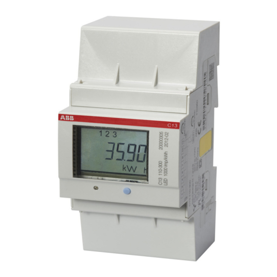
Product Overview 2.2 Meter Type C13 meter The C13 is a compact meter for 3-phase metering. The meter is direct connected for currents up to max. 40 A. Product label The meter type information that is reflected on the product label is shown in the... - Page 12 Product Overview Item Description Frequency LED pulse frequency Pulse frequency Protection class II Operating temperature range Rated current ABB ID 2CMC486004M0201 User Manual Revision: A...
-
Page 13: Installation
Installation Chapter 3: Installation Overview This chapter describes how to mount the C13 meter and how to connect it to an electricity network. In this chapter 3.1 Mounting the Meter ................10 3.2 Environmental Considerations ............. 11 3.3 Installing the Meter ................12 3.3.1 Wiring Diagrams ................ -
Page 14: Mounting The Meter
Main Catalog (2CMC481003C0201). DIN-rail mounted The C13 meters are intended to be mounted on a standard (DIN 50022) DIN-rail. If this method of mounting is used no extra accessories are needed and the meter is fastened on the rail by snapping the DIN-rail lock onto the rail. -
Page 15: Environmental Considerations
Installation 3.2 Environmental Considerations Ingress protection To comply with the protection requirements the product must be mounted in pro- tection class IP 51 enclosures, or better, according to IEC60259. Mechanical environment In accordance with the Measuring Directive (2014/32/EU), the product complies with M1, which means that it can be operated in “...locations with vibration and shocks of low significance, e.g. -
Page 16: Installing The Meter
Turn on the mains power. Verify the The C13 meter has a red LED next to the push button on the front of the meter that flashes proportionally to the active energy. The LED has a fixed pulse fre- installation quency of 1000 imp/kWh and can be used to test and verify the installation. -
Page 17: Wiring Diagrams
Installation 3.3.1 Wiring Diagrams 4-wire connection The following diagram shows a 4-wire connection of a direct connected 3-phase meter: 3.3.1.1 Outputs Fixed, 1 output 2CMC486004M0201 Revision: A User Manual... - Page 18 Installation 2CMC486004M0201 User Manual Revision: A...
-
Page 19: User Interface
User Interface Chapter 4: User Interface Overview This chapter gives an overview of the display and of the functions of the button on the meter. In this chapter The following topics are covered in this chapter: 4.1 Display and buttons ................16 4.2 Menu Structure .................. -
Page 20: Display And Buttons
User Interface 4.1 Display and buttons Display The display consists of icons, digits and letters. The measured value/menu options are displayed with large letters. The measured unit is displayed on the bottom- right side of the display, and the status icons are displayed at the upper part of the display, see figure below. -
Page 21: Menu Structure
User Interface 4.2 Menu Structure Overview This section will give an introduction to the menu structure. Menu structure The menu structure of the meter can be viewed in the following figure View menu Set menu Select function Set alarm – Active energy Alarm power –... - Page 22 User Interface Choice in menu Output on No. of No. of Unit Min. Max. value display digits decimals value Active energy max <numerical 999.999 resolution value> Active power Total <numerical 99999 value> Active power <numerical 99999 Phase 1 value> Active power <numerical 99999 Phase 2...
- Page 23 User Interface Choice in menu Output on No. of No. of Unit Min. Max. value display digits decimals value CRC Part 1 0000 FFFF CRC Part 2 0000 FFFF Error Er <numerical value> Set menu The set menu is used to set different options in the meter. The set menu is reached by using the long press when located in the view menu.
- Page 24 User Interface Choice in menu Output on display Explanation Alarm power factor By choosing this option, the alarm will be set regarding to the measured power factor. Pulse output By choosing this option, the pulse output function will be ac- tivated.
-
Page 25: Meter Settings
Meter Settings Chapter 5: Meter Settings Overview This chapter describes how to configure the functions of the meter, including alarm settings. In this chapter The following topics are covered in this chapter: 5.1 Setting the Output ................22 5.2 Setting the Alarm ................. 24 2CMC486004M0201 Revision: A User Manual... -
Page 26: Setting The Output
5.1 Setting the Output About the output The C13 meter has one output which can be used for three different purposes. When one of the three options has been chosen for the output, the remaining two options are automatically disabled. - Page 27 Meter Settings Disable output The output can also be disabled by performing the following steps when located in the view menu. Step Action Comment When located in the view menu, use the long press to get to the set menu Use the long press to get to the selection of func- tion menu.
-
Page 28: Setting The Alarm
Meter Settings 5.2 Setting the Alarm About the alarm The alarm function gives the user the possibility to set an alarm that will trigger when a defined limit is reached by the measured value. See table for more infor- mation. Choice in menu Unit Output on display... - Page 29 Meter Settings Step Action Comment Set the time frame that the measured value Use the short press to change must pass the set alarm value in order for the the value of the digit, and the alarm to trigger (Alarm on delay). long press to step through the different digits.
- Page 30 Meter Settings 2CMC486004M0201 User Manual Revision: A...
-
Page 31: Technical Description
Technical Description Chapter 6: Technical Description Overview This chapter describes the technical functions of the C13 meter. In this chapter The following topics are covered in this chapter: 6.1 Energy Values ..................28 6.2 Instrumentation ..................29 6.3 Outputs ....................30 6.4 Alarm .................... -
Page 32: Energy Values
Technical Description 6.1 Energy Values General The energy values are stored in energy registers. The different energy registers can be divided into: • Registers containing active energy. The energy values can be read directly on the display by using the button on the meter. -
Page 33: Instrumentation
Technical Description 6.2 Instrumentation Instrumentation The following table shows the complete instrumentation functions of the C13 me- ter. functions Instrumentation Active power L1 Active power L2 Active power L3 Voltage L1 - N Voltage L2 - N Voltage L3 - N... -
Page 34: Outputs
Technical Description 6.3 Outputs About outputs The C13 meter has one output which can be used for three different purposes. When one of the three options has been choosen for the output, the remaining two options are automatically disabled. • Alarm monitoring The output is used for monitoring if an alarm has been triggered or not. -
Page 35: Alarm
Technical Description 6.4 Alarm General The purpose of the alarm function is to enable monitoring of quantities in the meter. Monitoring can be set to high or low level detection. High level detection gives an alarm when the level of a quantity goes above the set level. Low level detection gives an alarm when the value goes below the set level. - Page 36 Technical Description 2CMC486004M0201 User Manual Revision: A...
-
Page 37: Technical Data
Technical data Chapter 7: Technical data Overview This chapter contains the technical specifications and the physical dimensions of the meter. In this chapter The following topics are covered in this chapter: 7.1 Technical Specifications ..............34 7.2 Physical Dimensions ................36 2CMC486004M0201 Revision: A User Manual... -
Page 38: Technical Specifications
Technical data 7.1 Technical Specifications Specifications for C13 direct connected meter Voltage/current inputs Nominal voltage 3x230/400 VAC Voltage range 3x220–240 VAC (-20% – +15%) Power dissipation voltage circuits 1.5 VA (0.6 W) total Power dissipation current circuits 0.04 VA (0.04 W) per phase at 230 VAC and I... - Page 39 Technical data Impulse voltage test 6 kV 1.2/50µs (IEC 60060-1) Surge voltage test 4 kV 1.2/50µs (IEC 61000-4-5) Fast transient burst test 4 kV (IEC 61000-4-4) Immunity to electromagnetic HF-fields 80 MHz – 2 GHz at 10 V/m (IEC61000-4-3) Immunity to conducted disturbance 150kHz –...
-
Page 40: Physical Dimensions
Technical data 7.2 Physical Dimensions The following drawing shows the physical dimensions of the C13 meter 2CMC486004M0201 User Manual Revision: A... -
Page 41: Troubleshooting
Troubleshooting Chapter 8: Troubleshooting Overview This chapter describes the error codes and the warnings that can be received from the meter. In this chapter The following topics are covered in this chapter: 8.1 Error Codes and Warnings ..............38 2CMC486004M0201 Revision: A User Manual... -
Page 42: Error Codes And Warnings
Troubleshooting 8.1 Error Codes and Warnings Error codes Error code Description Er0041 Program CRC error Er0042 Persistent storage CRC error Er0051 Vref is not vdd/2 Er0052 Temperature sensor error Warnings Warning Description Er1007 Negative power Er1008 Frequency outside meter specification 2CMC486004M0201 User Manual Revision: A... -
Page 43: Service & Maintenance
Service & Maintenance Chapter 9: Service & Maintenance Overview This chapter contains information about service and maintenance of the product. In this chapter The following topics are covered in this chapter: 9.1 Service and Maintenance ..............40 2CMC486004M0201 Revision: A User Manual... -
Page 44: Service And Maintenance
Service & Maintenance 9.1 Service and Maintenance Service This product contains no parts that can be repaired or exchanged. A broken meter must be replaced. Cleaning If the meter needs to be cleaned, use a lightly moistened cloth with a mild deter- gent to wipe it.