Siemens SIDOOR AT40 System Manual
Automatic door controls
Hide thumbs
Also See for SIDOOR AT40:
- System manual (182 pages) ,
- Operating instructions manual (6 pages) ,
- Operating instructions (4 pages)

Related Manuals for Siemens SIDOOR AT40


Summary of Contents for Siemens SIDOOR AT40
- Page 1 Automatic Door Controls SIDOOR AT40, ATD400V, ATD400K, ATD4xxW, ATD400S, ATE250S, ATD400T System Manual Edition 06/2016 siemens.com...
- Page 2 ___________________ AT40, ATD400V, ATD400K, ATD4xxW, Introduction ATD400S, ATE250S, ATD400T ___________________ General safety instructions ___________________ Automatic Door Controls Product family ___________________ Areas of application SIDOOR AT40, ATD400V, ATD400K, ___________________ ATD4xxW, ATD400S, ATE250S, Product combinations ATD400T ___________________ Controllers System Manual ___________________ Geared motors ___________________ Power supply ___________________...
- Page 3 Note the following: WARNING Siemens products may only be used for the applications described in the catalog and in the relevant technical documentation. If products and components from other manufacturers are used, these must be recommended or approved by Siemens. Proper transport, storage, installation, assembly, commissioning, operation and maintenance are required to ensure that the products operate safely and without any problems.
-
Page 4: Table Of Contents
Table of contents Introduction ............................11 General safety instructions ........................14 Product family ............................17 Products ..........................19 3.1.1 Controllers ..........................19 3.1.2 Geared motors ........................21 3.1.3 Accessories ..........................23 3.1.4 Power supply .......................... 26 3.1.5 Optional additional units ......................27 3.1.6 Software .......................... - Page 5 Table of contents 6.2.22 Obstruction detection ......................59 6.2.22.1 Obstruction detection CLOSE ....................59 6.2.22.2 Obstruction detection OPEN ....................60 6.2.22.3 SIDOOR ATD4xxW obstruction detection ................61 6.2.23 ImpulseDrive ........................... 65 6.2.24 Automatic ImpulseDrive ......................66 6.2.25 ImpulseStop ..........................67 6.2.26 Automatic ImpulseStop ......................
- Page 6 Table of contents Operation and parameter assignment ................. 109 6.4.1 Service buttons / Minimal editor ................... 110 6.4.1.1 Service buttons ........................110 6.4.1.2 Minimal editor ........................113 6.4.2 Terminal module ........................116 6.4.3 Operating options via additional units .................. 118 6.4.4 Parameter names.........................
- Page 7 Table of contents 6.10 Communication to PROFINET ....................191 6.10.1 Parameterization/startup record ................... 191 6.10.2 Configuration ......................... 193 6.10.3 Diagnostics ........................... 193 6.10.4 Device roles and provider-consumer model ................. 194 6.11 Structure of user data/process data ..................195 6.11.1 Parameter interface ......................196 6.11.1.1 Parameter ID (PKE) ......................
- Page 8 Table of contents Geared motors ............................. 232 Description ........................... 232 Installation ..........................233 Connecting terminals ......................238 7.3.1 Conductor assignment of the motor plug ................238 Technical specifications ....................... 239 7.4.1 Dimension drawing of SIDOOR M2 with rubber-metal anti-vibration mount and mounting bracket........................
- Page 9 Profiles and adjustment ranges .................... 296 A.1.1 Profile name .......................... 296 A.1.2 SIDOOR M2 L / R ......................... 297 A.1.2.1 SIDOOR AT40/ATD400S ..................... 297 A.1.2.2 SIDOOR ATD400W ......................298 A.1.2.3 SIDOOR M2 adjustment ranges ................... 299 A.1.3 SIDOOR M3 L / R ......................... 300 A.1.3.1...
- Page 10 Table of contents A.1.9 SIDOOR M5 L / R ........................ 320 A.1.9.1 SIDOOR AT40 ........................320 A.1.9.2 SIDOOR ATD4xxW ......................321 A.1.9.3 Adjustment ranges SIDOOR M5 ..................322 A.1.10 SIDOOR MEG250 ........................ 324 A.1.10.1 SIDOOR ATE250S ......................324 A.1.10.2 Adjustment ranges SIDOOR MEG250 ................325 Configuration record ......................
-
Page 11: Introduction
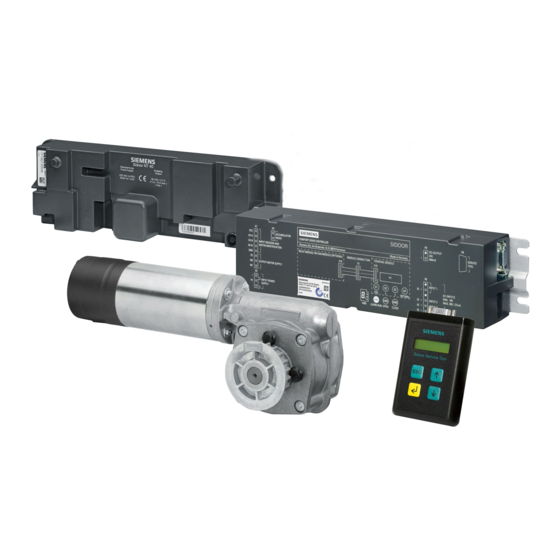
Introduction Content of the System Manual This System Manual describes SIDOOR door drives. A SIDOOR door drive consists of at least the following components: ● Controller ● Geared motor ● Power supply Optional additional units can also be connected (for example, the SIDOOR Service Tool). The individual products and their interactions are described in this System Manual. - Page 12 (http://support.automation.siemens.com/WW/view/en/50247080/133100). Figures The figures in this System Manual illustrate SIDOOR User Software Version 1.11 and the SIDOOR AT40 RELAY controller / CAN Version 1.40. The illustrations for other versions may differ slightly. Information on the Internet You can find more information about SIDOOR door drives and their applications on the Internet (www.siemens.com/sidoor).
- Page 13 Introduction History Version Change 10/2010 First edition 02/2014 Revised and expanded edition 04/2014 Edition revised and expanded to include the SIDOOR ATD420W control- ler. 07/2014 Revised and expanded edition 11/2014 Edition revised and expanded to include the SIDOOR ATD430W control- ler.
-
Page 14: General Safety Instructions
General safety instructions Qualified personnel Qualified personnel have the following qualifications: ● Training, instruction or authorization to switch on and off electric circuits and devices/systems in compliance with safety engineering standards. ● Training or instruction in the maintenance and use of appropriate safety equipment in compliance with safety engineering standards. - Page 15 General safety instructions Parameter assignment and configuration WARNING Risk of injury and material damage due to excessive forces of the door Exceeding the maximum static closing force and opening force, if present, may lead to injuries to persons or damage to the door drive and mechanical components of the door. After commissioning, have the maximum static forces checked by the service personnel, and adjusted to the limit value if it is excessive.
- Page 16 Siemens recommends strongly that you regularly check for product updates. For the secure operation of Siemens products and solutions, it is necessary to take suitable preventive action (e.g. cell protection concept) and integrate each component into a holistic, state-of-the-art industrial security concept.
-
Page 17: Product Family
Product family SIDOOR Door control system is the general term for a controller of an access system. The SIDOOR product family is primarily intended for operating sliding doors. Different versions of SIDOOR controllers enable both horizontal and vertical doors to be operated. Door control systems are characterized by the fact that there are always two defined states: namely for the open and closed positions of the door. - Page 18 EC systems are three-phase driven, and are electronically commutated. SIDOOR controllers and SIDOOR motors use the technologies as shown below: Table 3- 1 Overview of technologies used DC technology EC technology Controllers SIDOOR AT40 ✓ — SIDOOR ATD400V ✓ — SIDOOR ATD400K ✓...
-
Page 19: Products
The controllers are designed for different areas of application. The following table provides an overview of the available controllers. Versions Controller Article No. Description Elevators SIDOOR AT40 RELAY 6FB1111-0AT10-3AT2 Controller for horizontal elevator doors, up to 600 kg door • weight Relay module •... -
Page 20: Sidoor Atd410W
Product family 3.1 Products Controller Article No. Description SIDOOR ATD410W 6FB1141-4AT10-3WE2 Controller for machine tools, up to 600 kg door weight • USS bus interface to the higher-level controller (USS • module) SIDOOR ATD420W 6FB1141-2AT10-3WE2 Controller for machine tools, up to 600 kg door weight •... -
Page 21: Geared Motors
Product family 3.1 Products 3.1.2 Geared motors Geared motors form the maintenance-free drive unit in the door drive. The geared motors feature DC motors with non-self-locking gearing and are speed-controlled. The set force and speed limits are not exceeded. The power is transmitted by a gear rack or chain. Toothed belts or chains pass over a deflector pulley, and can be fitted with 2 clutch holders. - Page 22 Product family 3.1 Products Geared motor Article No. Description SIDOOR M4 L 6FB1103-0AT10-3MC0 Geared motor, pinion left, max. 400 kg door weight • Cable length 1.5 m • SIDOOR M4 R 6FB1103-0AT11-3MC0 Geared motor, pinion right, max. 400 kg door weight •...
-
Page 23: Accessories
Product family 3.1 Products 3.1.3 Accessories Accessories Article No. Description SIDOOR rubber-metal anti- 6FB1104-0AT01-0AD0 Rubber-metal anti-vibration mount for quiet operation of • vibration mount the door drive system Recommended for mounting SIDOOR M4 R / L, MDG400 • R / L, M5 R / L and MDG400 NMS R / L geared motors 6FB1104-0AT02-0AD0 Rubber-metal anti-vibration mount for quiet operation of •... - Page 24 Product family 3.1 Products Accessories Article No. Description SIDOOR 6FB1124-0BM00-0CB0 Cable from the SIDOOR AT-EB expansion unit to the • CABLE-RS485-MM-2m SIDOOR ATD400S (Can also be used to connect the SIDOOR AT-EB expan- sion unit to the SIDOOR ATE250S) Cable length 2 m •...
- Page 25 Cable for connecting the SIDOOR ATD430W controller to the higher-level SIMATIC controller DIN rail holder 6FB1144-0AT00-3AS0 DIN rail holder with fixing screws for SIDOOR ATD4xxW controllers You will find more accessories in the Industry Mall (http://www.siemens.com/siplus/mall) AT40, ATD400V, ATD400K, ATD4xxW, ATD400S, ATE250S, ATD400T System Manual, 06/2016, A2B00096162-AN...
-
Page 26: Power Supply
Product family 3.1 Products 3.1.4 Power supply SIDOOR power supplies connect the controllers to the respective application-specific power supply. Device selection Power supply Article No. Description SIDOOR NT40 6FB1112-0AT20-3PS0 Power supply for controllers without an integrated power supply unit. SIDOOR Transformer 6FB1112-0AT20-2TR0 DC voltage supply (Page 276) AT40, ATD400V, ATD400K, ATD4xxW, ATD400S, ATE250S, ATD400T... -
Page 27: Optional Additional Units
Product family 3.1 Products 3.1.5 Optional additional units Additional units meet a range of customer requirements in order to ensure the universal implementation and maintenance of the system. The additional units are easy to connect to a deenergized controller via the interfaces provided –... -
Page 28: Software
6FB1105-0AT01-6SW0 The package includes the following components: Installation CD (Software Kit) • – Sidoor User Software – Siemens HCS12 Firmware Loader – Sidoor USB to UART Bridge driver – License provisions – SIDOOR Software Kit Operating Instructions 1 x USB adapter •... -
Page 29: Areas Of Application
The following controllers are offered for elevator applications: ● SIDOOR AT40 The comfort SIDOOR AT40 elevator door drive is an "intelligent" door drive with which cabin and shaft doors can be opened and closed at adjustable speeds and accelerations. ● SIDOOR ATD400V The SIDOOR ATD400V hoisting and rolling shutter drive for elevators is an "intelligent"... -
Page 30: Industrial Applications
The controller is interfaced to a USS bus by means of a modular USS module. You can find more detailed information about the USS protocol online at Industry Online Support (http://support.automation.siemens.com/WW/view/de/24178253/0/en). – SIDOOR ATD420W The PROFIBUS DP interface is realized by means of a modular PROFIBUS module (AT-PB). -
Page 31: Railways
Areas of application 4.3 Railways The contents and structure of the user data transferred by the fieldbus systems correspond to the PROFIBUS "variable speed drives" profile. Use of this profile is also the basis for integration of the controller in the industrial environment. Both communicative integration via a fieldbus system and safety-related aspects play an important role here. -
Page 32: Product Combinations
Product combinations The following table shows which products you can combine with which controllers. Table 5- 1 Overview of product combinations SIDOOR … AT40 ATD400V ATD400K ATD4xxW ATD400S ATE250S ATD400T Geared motors SIDOOR M2 ✓ — — — ✓ — —... -
Page 33: Controllers
Controllers Description Overview SIDOOR AT40 / ATD400V ① Connecting terminals ② Relay module / CAN module ③ Service buttons / Minimal editor ④ Terminal module SIDOOR ATD400K / ATD400S / ATD400T ① Connecting terminals ② Relay module / USS module / PROFIBUS module (not with ATD400S) ③... - Page 34 Controllers 6.1 Description SIDOOR ATD4xxW ① Connecting terminals ② Relay module/USS module/PROFIBUS module/PROFINET module ③ Service buttons/Minimal editor ④ Terminal module SIDOOR ATE250S ① Connecting terminals ② Terminal module AT40, ATD400V, ATD400K, ATD4xxW, ATD400S, ATE250S, ATD400T System Manual, 06/2016, A2B00096162-AN...
-
Page 35: Drive Functions
Controllers 6.2 Drive functions Drive functions 6.2.1 Overview This Section describes the complete range of drive functions of SIDOOR controllers. The following table provides an overview of the SIDOOR controllers and their individual drive functions. Overview of drive functions Different drive functions have been implemented in the controllers according to their areas of application. - Page 36 Controllers 6.2 Drive functions SIDOOR AT40 ATD400V ATD400K ATD401W ATD410W/ ATD400S ATE250S ATD400T ATD420W/ ATD430W DOOR OPEN (command ✓ ✓ ✓ ✓ ✓ ✓ — — ✓ given via digital inputs) (V1.01 and (Page 55) higher) Partial opening (Page 56) —...
- Page 37 Controllers 6.2 Drive functions SIDOOR AT40 ATD400V ATD400K ATD401W ATD410W/ ATD400S ATE250S ATD400T ATD420W/ ATD430W Emergency release (Page 82) ✓ ✓ ✓ ✓ ✓ ✓ ✓ ✓ ✓ Learn run (Page 83) ✓ ✓ ✓ ✓ ✓ ✓ ✓ ✓ ✓...
- Page 38 External closing force is not provided for the customer side, however it can be installed. (See the notes in the descrip- tion of function) Drive function parameter assignment The respective parameters for the drive functions are fixed for the SIDOOR AT40, ATD400V, ATD400K, ATD401W, ATD400S, ATE250S and ATD400T controllers and cannot be changed.
-
Page 39: Light Barrier
CLOSE command is inactive does not change the state. Connection and parameter assignment SIDOOR AT40 / ATD400V / ATD400K (RELAY LB) The light barrier signal can be connected via "Input 1" (X6). See also Section Digital input signals (Page 131). The connected signal must be activated via the SIDOOR Service Tool Main menu >... - Page 40 Controllers 6.2 Drive functions Signals Signal Description 1 (voltage applied) Light barrier is not interrupted and the door closes when the DOOR CLOSE command is present 0 (voltage not applied) Light barrier is interrupted and the door opens when the DOOR CLOSE command is present* * The response of SIDOOR ATD4xxW controllers also depends on the particular system mode.
-
Page 41: Motion Detector
Controllers 6.2 Drive functions 6.2.3 Motion detector Description of function If a signal is active at the input of the connected motion detector, the door opens according to the set driving curve as long as the command is active. If the door is opened less than 1 cm, the motion detector signal is ignored. -
Page 42: Dcops (Door Closed/Opened Position Sensor)
Controllers 6.2 Drive functions Connection and parameter assignment The DCPS signal can be connected via "Input 1" of the terminal X6. See also Section Digital input signals (Page 131). The connected signal must be activated via the SIDOOR Service Main menu > General setup > Special parameters > Input 1 Tool ( Note The light barrier and DCPS functions cannot be implemented simultaneously. - Page 43 Controllers 6.2 Drive functions Connection and parameter assignment The DCOPS signal can be connected to SIDOOR ATD4xxW controllers via "Input 1" of the terminal X6. See also Section Digital input signals (Page 131). Main menu > The connected signal must be activated via the SIDOOR Service Tool ( General setup >...
-
Page 44: Type 2 Espe
Controllers 6.2 Drive functions 6.2.6 Type 2 ESPE Function description A light array / light curtain is the part of the electro-sensitive protective equipment (ESPE) that is connected to the machine controller and assumes a defined state when the sensing device is triggered during intended use. - Page 45 Controllers 6.2 Drive functions Signals Signal Description 1 (voltage applied) Light curtain is not interrupted. 0 (voltage not applied) Light curtain is interrupted*. * The response of SIDOOR ATD4xxW controllers also depends on the particular system mode. See the table below. Table 6- 2 Response of SIDOOR ATD4xxW controllers to an active light curtain signal Mode...
-
Page 46: Pressure-Sensitive Edge (Sr)
Controllers 6.2 Drive functions 6.2.7 Pressure-sensitive edge (SR) Function description The pressure-sensitive edge is connected to the machine control and assumes a defined state if the sensor device is addressed during proper operation. Connection and parameter assignment The output signal switching device of the pressure-sensitive edge is connected to "Input 1" of the terminal X6. -
Page 47: Gate Interlocking
Controllers 6.2 Drive functions Signals Signal Meaning 1 (high) Pressure-sensitive edge is not interrupted and is fault-free. 0 (low) Pressure-sensitive edge is interrupted or defective*. * The response of SIDOOR ATD4xxW controllers also depends on the particular system mode. See the table below. -
Page 48: Door Locked
Controllers 6.2 Drive functions 6.2.9 Door locked Description of function If the "Door locked" command is active, the door control system responds as follows: ● The door drive is torque-free. ● The incoming commands "DOOR OPEN" and "Motion detector" are not evaluated by the controller. -
Page 49: Nudge
Controllers 6.2 Drive functions 6.2.10 Nudge Description of function If a "Nudge" command is present, the reversing unit is deactivated. The input signals CLOSE and NUDGE must be active so that the NUDGE operating state is only effective in the closing direction. -
Page 50: Force And Energy Profiles (Ndg Mode)
Controllers 6.2 Drive functions 6.2.12 Force and energy profiles (NDG mode) SIDOOR ATD4xxW controllers support two individually parameterizable force and energy profiles. Parameter assignment You can configure the following parameters equally via the parameter interface, the service tool and the terminal. Table 6- 4 Force and energy profile parameter overview Normal operation... -
Page 51: Slow Driving Curve Profile
Controllers 6.2 Drive functions 6.2.13 Slow driving curve profile SIDOOR ATD4xxW controllers support a parameterizable, decelerated speed profile (slow profile), to which it is possible to switch over to flexibly. Parameter assignment You can configure the following parameters equally via the parameter interface, the service tool and the terminal. -
Page 52: Automatically Delayed Motion
Controllers 6.2 Drive functions 6.2.14 Automatically delayed motion Description of function SIDOOR ATD400T If the "Open" / "Close" command is present, relay X13 is activated, and the door is not opened / closed until the preset timer "Time delay before movement" expires. SIDOOR ATD400S and SIDOOR ATE250S If the "Open"... -
Page 53: Cord-Operated Switch
Controllers 6.2 Drive functions 6.2.15 Cord-operated switch Description of function The cord-operated switch command has the same function as the GATE OPEN command. However, it also offers the option of partial opening. "Opening width in percent" and "Hold- open time cord operated switch" can be set in the Special parameters menu. The cord- operated switch command remains present until a new input signal is activated or the "Hold- open time cord operated switch"... -
Page 54: Door Close (Command Given Via Digital Inputs)
Controllers 6.2 Drive functions 6.2.16 DOOR CLOSE (command given via digital inputs) Description of function The DOOR CLOSE command must remain present continuously in order to close the door. After the door has closed, it is held in this position by the torque that can be adjusted by the parameter "Continuous torque CLOSE"... -
Page 55: Door Open (Command Given Via Digital Inputs)
Controllers 6.2 Drive functions 6.2.17 DOOR OPEN (command given via digital inputs) Description of function The DOOR OPEN command opens the door according to the set driving curve as long as the command is present. The door reaches the OPEN position at creep speed. Then, if the DOOR OPEN command is present, the door is held open by the torque that can be adjusted by the parameter "Continuous torque OPEN". -
Page 56: Partial Opening
Controllers 6.2 Drive functions 6.2.18 Partial opening Description of function A second open position can be implemented using the "partial opening" drive function. A "partial opening" describes an opening movement with a set curve profile up to the partial opening position. When partial opening is active, the learned or real door width is replaced with the parameterized partial opening width. -
Page 57: Restart After Power Failure
DOOR CLOSE command is present, the 7-segment display (H401)/digital display (H1) shows "4". This function prevents thermal overloading of the motor. SIDOOR AT40 Reversing the direction of rotation or restarting the controller several times puts a disproportionate strain on the drive motor. -
Page 58: Vandalism Protection/Continuous Door Monitoring
Controllers 6.2 Drive functions 6.2.21 Vandalism protection/continuous door monitoring Description of function The vandalism protection/continuous door monitoring function offers protection against undesired external system motion. If the motor is deenergized, the motor speed is monitored by the controller. If the maximum speed of 250 mm/s is exceeded, the controller actively decelerates the motor to 50 mm/s, and then switches the drive back to "deenergize". -
Page 59: Obstruction Detection
Controllers 6.2 Drive functions 6.2.22 Obstruction detection 6.2.22.1 Obstruction detection CLOSE Description of function If the door is obstructed in the CLOSE direction with a DOOR CLOSE command present, the door stops and reverses direction. After reaching the OPEN position, the door closes again at normal speed to within about 2 cm of the obstruction. -
Page 60: Obstruction Detection Open
Controllers 6.2 Drive functions 6.2.22.2 Obstruction detection OPEN Description of function The door stops if it is obstructed in the "OPEN" direction when the DOOR OPEN command is present. After approximately 2 s, the door automatically tries to reach the OPEN position again. -
Page 61: Sidoor Atd4Xxw Obstruction Detection
Controllers 6.2 Drive functions 6.2.22.3 SIDOOR ATD4xxW obstruction detection Description of function SIDOOR ATD401W (SIDOOR ATD4xxW factory default, firmware version 1.03 or higher) If the controller detects an obstruction in the opening or closing direction with the aid of obstruction detection, it reverses once by 20 cm, starts an attempt to retract and then switches to wait mode. - Page 62 Controllers 6.2 Drive functions Obstruction detection process The obstruction detection is based on two processes that are independent of the direction: force obstruction detection and stop obstruction detection. The following definitions are based on the speeds and are thus independent of the direction. The obstruction detection systems assume that the system is actively being moved (drive order).
- Page 63 Controllers 6.2 Drive functions Reversing (Retraction attempt) When an obstruction is detected, the obstruction reversing system can be used to initiate an immediate full or partial reverse - a retraction attempt. This system is simply termed "reverse". The system remains active as long as the initial drive order is not actively changed.
- Page 64 Controllers 6.2 Drive functions Slow obstruction approach The position of the last obstruction in the drive direction is automatically stored in the system. The speed is automatically reduced to the corresponding creep speed (p3670 or p3666) on approaching this position. The system calculates a braking ramp so that the reduced speed is reached at the set distance (parameter p3855 or p3872) from the stored position of the obstruction.
-
Page 65: Impulsedrive
Controllers 6.2 Drive functions 6.2.23 ImpulseDrive Description of function The ImpulseDrive analysis process detects and evaluates external impulses applied to the door system (for example, slight force exerted on the door in the opening or closing direction). In conjunction with the automatic ImpulseDrive system (see Section Automatic ImpulseDrive (Page 66)), a heavy door can be set in motion by applying a slight force to the door handle or door frame. -
Page 66: Automatic Impulsedrive
Controllers 6.2 Drive functions Speed-based ImpulseDrive analysis The analysis is based on the increments of the motor encoder or the actual speed derived from it. The evaluation is only made in the "S4: Z_operation" system state (see Image 6-33 Sequential control state graph (Page 216)) after the door command has been changed to "deenergize"... -
Page 67: Impulsestop
Controllers 6.2 Drive functions 6.2.25 ImpulseStop Function description The ImpulseStop analysis process detects and analyzes external forces acting on the door system/drive system. In conjunction with the automatic ImpulseStop system (see Section Automatic ImpulseStop (Page 68)), a door can be stopped with a light tug against the direction of travel. The process signals when an external opposing force (force with an opposite direction vector to that of the door movement) acts on the door or the drive. -
Page 68: Automatic Impulsestop
Controllers 6.2 Drive functions 6.2.26 Automatic ImpulseStop Function description The automatic ImpulseStop system is an expansion of the automatic ImpulseDrive system. This means that all the properties, configurations and preconditions defined for it are also applicable here. The system can be activated by the "ImpulseStop" expansion bit (see Table 6-75 DCMD expansion bits (Page 207)) in conjunction with automatic ImpulseDrive enabling (see Table 6-74 DCMD signal (Page 206)). -
Page 69: Assisteddrive
Controllers 6.2 Drive functions 6.2.27 AssistedDrive Function description AssistedDrive is an analysis process that detects and analyzes external forces acting on the door or drive system. In conjunction with the automatic AssistedDrive system (see Section Automatic AssistedDrive (Page 70)), a door can be moved with motor assistance without the need for buttons or sensors. -
Page 70: Automatic Assisteddrive
Controllers 6.2 Drive functions The result of the analysis is output by the signal state ASDrv. The falling signal edge therefore indicates that the assisting force has become too low. Assisted mode can be exited. This signal is independent of the drive direction. Note The falling edge of the ASDRV signal can only be reached when the difference between the setpoint and actual speeds falls below the defined value. -
Page 71: Initial Run/Reference Run (Power On)
Controllers 6.2 Drive functions Note After the automatic AssistedDrive system has canceled a drive order on account of an inadequate assisting force, ImpulseDrive detection becomes active again. However, the ImpulseDrive lead time (p1220) must be taken into account. It directly affects the signal chain of the automatic AssistedDrive system. -
Page 72: Positioning Mode
Controllers 6.2 Drive functions 6.2.30 Positioning mode Positioning mode serves to absolutely position the drive. The positioning system calculates a travel profile for the optimum movement of the drive to the required target position on the basis of the driving parameters and the current distance from the target position. Positioning mode does not include any position control and operates with an accuracy of 1 cm. -
Page 73: Belt Break Monitoring
Controllers 6.2 Drive functions 6.2.31 Belt break monitoring Description of function The function detects a torn belt. The detection is active in normal mode and initial mode. A torn belt is detected when the door movement exceeds the defined distance* (in the opening or closing direction). -
Page 74: Emergency Power Mode
Controllers 6.2 Drive functions 6.2.32 Emergency power mode Description of function If the line voltage fails, the connected emergency power module sends a signal to the controller. The speed-reduced driving curve profile (slow open und slow close) is automatically used in emergency power mode. Emergency power mode cannot be exited until the controller has reached the closed or open state in normal mode. -
Page 75: Friction Compensation
Controllers 6.2 Drive functions 6.2.33 Friction compensation Description of function The friction force profile of the door system is recorded with the current measuring device of the controller. The measurement data for both the opening and closing directions is recorded during the learn run. -
Page 76: Oscillation Protection
Controllers 6.2 Drive functions Note The corresponding internal force value, which is the result of the addition of the parameterized force value and the calculated friction force, is limited to the maximum value of the respective parameter. 6.2.34 Oscillation protection The oscillation protection prevents permanent oscillation of the door at the end stop. -
Page 77: Automatic Energy Limitation
Controllers 6.2 Drive functions 6.2.35 Automatic energy limitation Description of function SIDOOR controllers have a system that automatically limits the kinetic energy in the closing direction. WARNING Risk of injury due to moving mechanical parts Independently of the maximum closing speed automatically determined during the learn run, the kinetic energy of the door in the closing direction has to be checked by the commissioning engineer after a learn run. - Page 78 Controllers 6.2 Drive functions Speed limit curve (in the closing direction*) *SIDOOR ATD4xxW: Opening and closing directions The speed limit curve is the characteristic that determines the maximum permissible door speed (closing speed), v , as a function of the total door panel weight. According to EN 81, the maximum kinetic energy of the door in the closing direction must not exceed 10 joules.
- Page 79 Controllers 6.2 Drive functions Example from the following speed limit curve: ● Total door panel weight m = 180 kg => v = 0.21 m/s. Image 6-5 Speed limit curve for WKIN=4J Adjustment ranges You will find the adjustment ranges in Section Profiles and adjustment ranges (Page 296). AT40, ATD400V, ATD400K, ATD4xxW, ATD400S, ATE250S, ATD400T System Manual, 06/2016, A2B00096162-AN...
- Page 80 Controllers 6.2 Drive functions Maximum speeds The table below shows the maximum speeds depending on door weight and energy limiting: Table 6- 6 Maximum speeds [mm/s] depending on door weight and energy limiting Door weight Energy [J] [kg] 1000 1414 1732 2000 1000...
-
Page 81: External Closing Force
Controllers 6.2 Drive functions 6.2.36 External closing force Description of function Closing mechanisms in the form of a counterweight or a spring are permissible for a particular system. You will find the permissible counterweights in Section Technical specifications (Page 223). WARNING Risk of injury due to moving mechanical parts Make sure that with an additional external closing force the sum of external closing force... -
Page 82: Push To Open
Controllers 6.2 Drive functions 6.2.37 Push to open Description of function The controller automatically detects a DOOR OPEN command if a door is pulled manually in the opening direction by more than 2 cm. 6.2.38 Pull to close Description of function The controller automatically detects a DOOR CLOSE command if a door is pulled manually by more than 2 cm in the closing direction. -
Page 83: Learn Run
Controllers 6.2 Drive functions 6.2.40 Learn run Description of function A learn run serves to determine and store the characteristics of a particular system. Note For the M4, MDG400, MDG400 NMS and M5 motors, the output transmission (Page 86) must be checked prior to each learn run and adjusted if necessary.* * SIDOOR ATD4xxW Types of learn run (via learn run button) Two types of learn run can be made if the learn run button is pressed as follows:... - Page 84 Controllers 6.2 Drive functions Learning in new motors (ATD4xxW) The learned motor type is stored in the controller and compared with the connected motor when the controller is switched on. The controller's operating status display shows the status code "5" if the learned motor type differs from the connected one. A new learn run (when the line voltage is applied) or a special learn run is needed to learn in the new motor type.
-
Page 85: Force Limit For Learn Run
Controllers 6.2 Drive functions Querying determined values The values determined for the effective weight and the door width can be queried via the terminal module. SIDOOR ATD4xxW SIDOOR ATD4xxW controllers also enable querying via the following parameters: ● Effective weight: r2101 ●... -
Page 86: Output Transmission
Controllers 6.2 Drive functions 6.2.42 Output transmission Description of function For the M4, MDG400. MDG400 NMS and M5 motors, the output transmission must be configured. The output transmission describes the transformation of rotational into translational motion. Therefore: The distance [mm] that the door travels with one revolution [rev] of the transmission output shaft. -
Page 87: Free Function Blocks (Fblock)
Controllers 6.2 Drive functions 6.2.43 Free function blocks (FBLOCK) 6.2.43.1 Overview In some applications it is necessary to control the drive via digital signals. To this end, you can configure an individual logic using the logic elements shown in the following figure. ①... -
Page 88: Configuring The Logic
Controllers 6.2 Drive functions 6.2.43.2 Configuring the logic The free function blocks are configured at the parameter level. The input of a function block can be linked to any output by entering the output's Q number in the input's REF parameter. The outputs' Q numbers can be found in Image 6-6 FBLOCK overview (Page 87). - Page 89 Controllers 6.2 Drive functions Drive orders In parallel with logical signal combination, a drive order can be assigned to the Q outputs. Door commands that are assigned to the outputs are only active as long as the assigned output is active (jog mode). A drive order is composed of a door command "DCMD" and an optional door command expansion bit "DCMD expansion".
-
Page 90: Digital And Logical Input Signals
Controllers 6.2 Drive functions Signal processing All outputs are recalculated in each processing cycle (10 ms) on the basis of the current input signal states. The cycle's output signals are calculated exactly in the order of the Q numbers (beginning with Q0). If the output Q22 ("NOT0") is used as the input signal of "AND0", its output Q17 is not recalculated until the next cycle. -
Page 91: Special Function Blocks
Controllers 6.2 Drive functions Logical input signals To be able to map internal dependencies in the logic, selected system states are made available as logical input signals. Logical signal source Description Logical 0 "low" Logical 1 "high" Motor deenergized Motor stopped System opened System closed Fault... -
Page 92: Frequency Analysis Blocks
Controllers 6.2 Drive functions 6.2.43.7 Frequency analysis blocks An input signal can be analyzed for specific frequencies and duty factors via the "FRQ" frequency blocks. Two identical frequency analysis blocks are available, capable of detecting frequencies of 1 Hz and 0.5 Hz with a duty factor of 20 %. The detection criteria and the valid tolerances are described in detail in the following figure. -
Page 93: Counter Block
Controllers 6.2 Drive functions 6.2.43.9 Counter block The "COUNTER" block increments the internal counter value in the event of a positive edge at the input. The maximum counter value is 2. The counter value is reset in the event of an overflow: 0 →... -
Page 94: Drive Orders
Controllers 6.2 Drive functions 6.2.44 Drive orders The drive is controlled by means of drive orders. A drive order is composed of the following: Drive order = door command + door command expansion bit Combinations The following table shows the combination of the door command and the door command expansion bit that lead to modification of the applicable door command. - Page 95 Controllers 6.2 Drive functions Shutdown/deceleration functions In an unlimited system, the shutdown and deceleration functions are split into the following: "rapid stop", "ramp stop" and "coasting down". These definitions do not apply in a door system because these are to be considered as limited systems. Table 6- 9 Shutdown/deceleration functions in an unlimited system Function...
- Page 96 Controllers 6.2 Drive functions Sources of drive orders Drive order Description source Service button Activating a service button results an immediate switchover to the local mode (see Local/master opera- tion (Page 215)). The Deenergize drive order is active where no button is pressed. S401 (learn run) If S401 is pressed for approx.
- Page 97 Controllers 6.2 Drive functions Prioritization of door command sources Door commands can be issued via different sources. A higher-priority drive order overwrites a lower-priority drive order. The service interfaces generally have the highest priority because they are intended for commissioning and service purposes. Table 6- 11 Prioritization of door command sources Priority...
-
Page 98: Safety Concept Atd4Xxw
Controllers 6.3 Safety concept ATD4xxW Safety concept ATD4xxW The SIDOOR controllers ATD4xxW dispose of an extensive safety package. The safety functions fulfill the requirements according to DIN EN ISO 13849-1 Cat 2 PL d (Performance Level). The scope of the safety functions includes: ●... -
Page 99: Internal Signal Routing
Controllers 6.3 Safety concept ATD4xxW 6.3.3.1 Internal signal routing The following figure illustrates the input terminals and the internal wiring to the processor. The input signals are located at processor port M. Separate reference potentials 0M, 1M and 2M can each be defined for Input 2, Input 3, Input 4 and for Input 1 and Input 0. The input signals are provided with internal pull-ups and there are no components between the input terminals and the processor that are capable of oscillation. - Page 100 Controllers 6.3 Safety concept ATD4xxW Antivalent connection of an antivalent sensor to two channels A 2-channel sensor is required for the signal (1oo2 evaluation) Image 6-10 Antivalent connection of a sensor (type 1) to two channels Image 6-11 Antivalent connection of a sensor (type 2) to two channels* * Two 1-channel sensors can also be connected as an alternative.
-
Page 101: Frequency-Based Input Signals
Controllers 6.3 Safety concept ATD4xxW 6.3.3.3 Frequency-based input signals As well as 1oo2 evaluation with antivalent channels, a frequency-based system can also be used to implement fail-safe inputs according to PLd. Two frequency analysis blocks are available for this purpose, and can be linked to any input channel. - Page 102 Controllers 6.3 Safety concept ATD4xxW Antivalent connection of two redundant, two-channel antivalent sensors to two channels Two redundant 2-channel antivalent sensors are needed for the signal (1oo2 evaluation) Image 6-13 Two-hand control device example The output of the "AND0" block can be directly assigned a drive order or can be assigned the prioritized STOP door command via an additional negation block.
-
Page 103: Emergency Stop Concept In Accordance With Stop Category 1
Controllers 6.3 Safety concept ATD4xxW Image 6-14 Two-hand control device example parameterization 6.3.3.5 Emergency stop concept in accordance with stop category 1 This concept describes the implementation of the emergency stop function according to stop category 1 in compliance with EN ISO 13850:2008. Safe motor shutdown SIDOOR ATD4xxW controllers have an internal, cyclically tested and monitored second shutdown route according to PLd. -
Page 104: Concept Of Fail-Safe Digital Control (Door Open/Close) With Emergency Stop Via 4
Controllers 6.3 Safety concept ATD4xxW 6.3.3.6 Concept of fail-safe digital control (door OPEN/CLOSE) with emergency stop via 4 digital inputs This concept describes one implementation variant of the emergency stop function in accordance with stop category 1 as specified in EN ISO 13850:2008, with fail-safe control (in accordance with PLd) of door OPEN/CLOSE drive orders via 4 digital inputs. - Page 105 Controllers 6.3 Safety concept ATD4xxW Image 6-17 Interfacing safe (PLd) digital door control (OPEN/CLOSE) with emergency stop (encoder type 2) Door commands The door command with the highest priority is STOP → ramp stop. The status following the ramp stop can be defined using the "special" door command expansion bit as either "source voltage brake activated"...
- Page 106 Controllers 6.3 Safety concept ATD4xxW Implementation To implement this interfacing connection, the emergency stop signal must be routed in a safety-related manner to the SIDOOR controller (2-channel antivalent evaluation here) and internally linked with a stop door command. A negation block must be configured because a low-active emergency stop signal is used here.
-
Page 107: Concept Of Fail-Safe Digital Control (Door Open/Close) With Emergency Stop Via 3
Controllers 6.3 Safety concept ATD4xxW 6.3.3.7 Concept of fail-safe digital control (door OPEN/CLOSE) with emergency stop via 3 digital inputs This concept describes one implementation variant of the emergency stop function in accordance with stop category 1 as specified in EN ISO 13850:2008, with fail-safe control (in accordance with PLd) of door OPEN/CLOSE drive orders via 3 digital inputs. - Page 108 Controllers 6.3 Safety concept ATD4xxW Implementation For the implementation of this interfacing variant, the emergency stop signal is integrated into the redundant antivalent safety circuit. The emergency stop element itself is only routed to the SIDOOR controller through 1 channel. It is combined via an internal enabling logic with a STOP door command of the highest priority.
-
Page 109: Operation And Parameter Assignment
Controllers 6.4 Operation and parameter assignment Operation and parameter assignment The service buttons can be used to operate the controller. The following options are available to parameterize the controller. 1. Parameter assignment with the minimal editor (not for ATE250S and ATD4xxW) 2. -
Page 110: Service Buttons / Minimal Editor
Controllers 6.4 Operation and parameter assignment 6.4.1 Service buttons / Minimal editor Overview SIDOOR AT40 / ATD400V / ATD400W / ATD4xxW / ATD400K / ATD400S / ATD400T ① 7-segment display ② Learn run button ③ Service button OPEN ④ Service button CLOSE... - Page 111 Controllers 6.4 Operation and parameter assignment Learn run (when the supply voltage is applied) Table 6- 13 Starting a learn run when the line voltage is applied Procedure H401 display H1 display Push the door into the CLOSED position. Disconnect the power supply from X3 (DC). Press and hold down the learn run button (S401 / S1 Connect the power supply to X3 (DC).
- Page 112 Software. In this case, the external input signals are disabled in some menus. You will find more information in Section SIDOOR Service Tool (Page 292) and in the SIDOOR Software Kit Operating Instructions (http://support.automation.siemens.com/WW/view/en/92711247). AT40, ATD400V, ATD400K, ATD4xxW, ATD400S, ATE250S, ATD400T...
-
Page 113: Minimal Editor
6.4.1.2 Minimal editor Using the minimal editor SIDOOR AT40, ATD400V, ATD400K, ATD400W, ATD400S and ATD400T controllers have a minimal editor. The minimal editor is a tool for changing the parameters of a controller if the terminal module, SIDOOR Service Tool or SIDOOR User Software are not available. In this case, the learn run button (S401) and the two service buttons (S402, S403) are assigned second functions. - Page 114 Controllers 6.4 Operation and parameter assignment Selecting a profile 1. Select the desired profile (1 to 6) by pressing the service button S402 (downwards) or S403 (upwards). 2. Confirm the profile you have set by pressing and holding down the learn run button (S401) until the dot lights up on the LED display (>...
- Page 115 Controllers 6.4 Operation and parameter assignment Performing a learn run Note The current driving parameters are overwritten by the factory parameters at the end of the learn run if the learn run button (S401) is pressed at the same time as the line voltage is applied.
-
Page 116: Terminal Module
The service buttons can only be used if the digital display on the terminal module is displaying the start text "Siemens ATxxx Servicetool" or the current door status. The S2 (Open) and S3 (Close) buttons are used as the OPEN and CLOSE service buttons respectively. - Page 117 Controllers 6.4 Operation and parameter assignment Operation Enter key – jumps to the next menu below Escape key – jumps back to the menu above Menu selection key – increases a parameter value Menu selection key – decreases a parameter value Parameters can be changed in both of the following menus: "MAIN MENU >...
-
Page 118: Operating Options Via Additional Units
The SIDOOR User Software is part of the SIDOOR Software Kit. You will find a detailed description of the SIDOOR Software Kit in the SIDOOR Software Kit Operating Instructions (http://support.automation.siemens.com/WW/view/en/92711247). ● SIDOOR Service Tool You will find a detailed description of the SIDOOR Service Tool in SIDOOR Service Tool (Page 292). - Page 119 Controllers 6.4 Operation and parameter assignment Full parameter name Parameter name as shown in the software Continuous torque (power) OPEN idle torque open Continuous torque (power) CLOSE idle torque close Cutter press-on torque CLOSE peak torque close Static opening force limit force open Static closing force limit force close...
-
Page 120: Navigation Structure
Controllers 6.4 Operation and parameter assignment 6.4.5 Navigation structure Menu entry is not present for: AT40, ATD400V, ATD400K, ATD4xxW, ATD400S, ATE250S Menu entry is not present for: ATD400S, ATE250S, ATD400W Menu entry present for: ATD4xxW AT40, ATD400V, ATD400K, ATD4xxW, ATD400S, ATE250S, ATD400T System Manual, 06/2016, A2B00096162-AN... - Page 121 Controllers 6.4 Operation and parameter assignment Menu entry present for: ATD4xxW Menu entry is not present for: ATD400K AT40, ATD400V, ATD400K, ATD4xxW, ATD400S, ATE250S, ATD400T System Manual, 06/2016, A2B00096162-AN...
- Page 122 Controllers 6.4 Operation and parameter assignment Menu entry present for: ATD4xxW AT40, ATD400V, ATD400K, ATD4xxW, ATD400S, ATE250S, ATD400T System Manual, 06/2016, A2B00096162-AN...
- Page 123 Controllers 6.4 Operation and parameter assignment Menu entry is not present for: AT40, ATD400V, ATD400K, ATD4xxW, ATD400S, ATE250S Menu entry is not present for: ATD400K Menu entry present for: ATD4xxW Menu entry is not present for: ATD400W, ATD400S, ATE250S Menu entry present for: ATD400K Menu entry for ATD4xxW and motor type M4, MDG400.
- Page 124 Controllers 6.4 Operation and parameter assignment Menu entry is not present for: ATE250S Menu entry present for: ATD400K Menu entry present for: ATD400K type 1 Menu entry present for: ATD4xxW AT40, ATD400V, ATD400K, ATD4xxW, ATD400S, ATE250S, ATD400T System Manual, 06/2016, A2B00096162-AN...
- Page 125 Controllers 6.4 Operation and parameter assignment Menu entry present for: ATD4xxW Menu entry present for: ATE250S AT40, ATD400V, ATD400K, ATD4xxW, ATD400S, ATE250S, ATD400T System Manual, 06/2016, A2B00096162-AN...
-
Page 126: Installation
Controllers 6.5 Installation Installation Requirements The installation site must fulfill the following requirements: ● Minimum clearance to surrounding parts 1 cm ● Even mounting surface ● Maximum distance from the power supply on account of the cable length: – SIDOOR NT40 / SIDOOR Transformer: 1.5 m –... - Page 127 Controllers 6.5 Installation ● SIDOOR ATD401W, ATD420W, ATD430W WARNING Risk of injury as a result of incorrect installation The controller must only be used in indoors. Final application-specific requirements must be observed. NFPA Industry environment: The controller fulfills the requirements for insulation against fire only when the cover is closed and, if it is installed outside of a control cabinet, only when installed horizontally.
- Page 128 Controllers 6.5 Installation Installation on a standard mounting rail (SIDOOR ATD4xxW) You need the SIDOOR standard rail mounting to mount a SIDOOR controller on a standard mounting rail. The SIDOOR standard rail mounting can be mounted on the controller in two different ways. This enables the controller to be mounted both vertically and horizontally on a standard mounting rail.
-
Page 129: Connecting Terminals And Interfaces
NOTICE Material damage Only use cables with a temperature range ≥ 85 °C 6.6.1 Wiring instructions Table 6- 15 Terminal information SIDOOR AT40 / ATD400V / ATD4xxW / ATD400K / ATD400S / ATD400T Interface Name Terminal Tool Solid con- Stranded... - Page 130 Controllers 6.6 Connecting terminals and interfaces Interface Name Terminal Tool Solid con- Stranded Stripping ductor conductor insula- tion CAN module PHOENIX: 1x 0.14 – 1x 0.14 – 1.5 30 – 0.22 - 7 mm 1803581 0.4x2.5 1.5 mm 0.25 X100 USS/PROFIBUS/ PHOENIX: 1x 0.14 –...
-
Page 131: Digital Input Signals
Controllers 6.6 Connecting terminals and interfaces 6.6.2 Digital input signals Slot X6 You can connect certain signals for drive functions at the inputs Input 1, Input 2, Input 3, Input 4 (X6) and Input 0 (X5). The following table shows how the drive function and input are assigned depending on the controller. - Page 132 Controllers 6.6 Connecting terminals and interfaces Note SIDOOR ATE250S The SIDOOR ATE250S controller does not have digital inputs. For the values of the input signals, the state "Off" is permanently transferred to the SIDOOR AT-EB expansion unit. Note SIDOOR ATD4xxW To avoid issuing unintentional door commands, remove the terminals X6 and X5 before changing the FBLOCK input configuration.
- Page 133 Controllers 6.6 Connecting terminals and interfaces Terminal circuit diagrams Table 6- 19 Terminal circuit diagrams for digital input signals a. Connection to an internal 24 V control volt- b. Connection to an external control voltage c. Connection to an internal 24 V control volt- d.
-
Page 134: Voltage Output
Controllers 6.6 Connecting terminals and interfaces ATD4xxW (firmware version 1.03 or higher) Table 6- 20 Terminal circuit diagrams for emergency stop with 3 digital inputs Connection to an internal 24 V control volt- Connection to an external control voltage "General setup > Special parameters > FBLOCK configuration > FBLOCK config. Emer- Adjustable via the service menu: gency stop 3 inp."... -
Page 135: Relay Module
Controllers 6.6 Connecting terminals and interfaces 6.6.4 Relay module Overview ① ② ③ ④ Protective cover ⑤ Fixing screw for the protective cover Image 6-23 Relay module AT40, ATD400V, ATD400K, ATD4xxW, ATD400S, ATE250S, ATD400T System Manual, 06/2016, A2B00096162-AN... - Page 136 6.6 Connecting terminals and interfaces Task The relay module's relay contacts can be used to report the following door states to the higher-level controller: Table 6- 21 SIDOOR AT40/ATD400V/ATD400K/ATD400W door states Relay Function contact The door has reached the "CLOSED" position The relay switches on when the controller has detected the CLOSED position and the pulse generator ceases to output pulses, i.e.
- Page 137 Controllers 6.6 Connecting terminals and interfaces Table 6- 23 SIDOOR ATD400T door states Relay Function contact Key illumination The relay switches on in the following cases: The controller detects the "locked" position (input "Door locked" active). The door is locked. •...
- Page 138 Controllers 6.6 Connecting terminals and interfaces Connection DANGER Risk of injury from dangerous electrical voltages When the housing cover of the controller is open, only a safety extra-low voltage of less than 42 V may be present. The protective cover provided must be used when a higher voltage (max.
- Page 139 Controllers 6.6 Connecting terminals and interfaces ① Cable ties (strain relief in housing) ② Cable ties (security against being pulled out within the protective cover) ③ Minimum length of the cable jacket within the protective cover: 5 mm ④ Minimum length of the single-insulation on the single cores: 5 mm ⑤...
-
Page 140: Can Module
Image 6-24 CAN module Task The CAN module enables the SIDOOR AT40 door controller to be connected to a CAN bus. A maximum of 32 nodes can be connected to the CAN bus. AT40, ATD400V, ATD400K, ATD4xxW, ATD400S, ATE250S, ATD400T... - Page 141 Controllers 6.6 Connecting terminals and interfaces Interface The interface is implemented according to CiA 301, profile 417. The SIDOOR Service Tool must be used to set the power of command to CAN, so that the controller can be addressed via the CAN bus. The factory settings of the major parameters are: Parameter Factory setting Command output...
- Page 142 CAN low bus cable The bus can be terminated with 120 ohms via the switch S1. You will find information about manufacturer-specific CANopen objects at Industry Online Support on the Internet (http://support.automation.siemens.com/WW/view/en/50247080/133300). AT40, ATD400V, ATD400K, ATD4xxW, ATD400S, ATE250S, ATD400T System Manual, 06/2016, A2B00096162-AN...
-
Page 143: Uss/Profibus/Profinet Module
Controllers 6.6 Connecting terminals and interfaces In addition to the CAN interface, there are also two relays on the CAN module. They can switch a maximum of 30 V and 0.5 A. The pin assignments are: Table 6- 26 Connector X11 Pin assignment Assignment Description... - Page 144 Controllers 6.6 Connecting terminals and interfaces Task The USS module enables the SIDOOR ATD410W door controller to be connected to a USS fieldbus. A maximum of 32 nodes (1 master, 31 slaves) can be connected to the USS bus. Interface Data is transmitted according to the standard EIA 485 (/2/).
-
Page 145: Profibus Module
GSD file Download SIEM81BA.GSD The GSD file is available online at Industry online support (http://support.automation.siemens.com/WW/view/en/99008084). You will find explanations of the basic functions and communication properties of the DP slave in the Section Communication to PROFIBUS (Page 186). Task The PROFIBUS module enables the SIDOOR ATD420W door controller to be connected to a PROFIBUS fieldbus. - Page 146 Controllers 6.6 Connecting terminals and interfaces Interface The ATD420W system is implemented as a slave using the DP-V0 protocol. Data transfer is cyclic with a class 1 DP master. An ASIC of the "SPC3" type is used for interfacing to PROFIBUS. RS 485 in accordance with ANSI TIA/EIA 485-A is used as the transmission technology.
- Page 147 Controllers 6.6 Connecting terminals and interfaces DIP switches (S501) The DIP switches (S501) on the device are used to set the PROFIBUS address of the DP slave. ① Status: 1≙ on ② Status: 0 ≙ off ③ DIP switch without function ④...
-
Page 148: Profinet Module
Controllers 6.6 Connecting terminals and interfaces 6.6.6.3 PROFINET module Overview ① Cable ties ② X1000 - Port 2 ③ X1000 - Port 1 ④ X100 ⑤ Protective cover An ASIC of the "ERTEC200P" type is used for interfacing to PROFINET. Ethernet is used as the transmission technology. - Page 149 Controllers 6.6 Connecting terminals and interfaces LED signals The following five status LEDs are available on the PROFINET module: Color Description Position Green Relay K1 picked up LED H1 switches on when the controller has detected the CLOSED position and the pulse generator ceases to output pulses.
- Page 150 Table 6- 28 GSD files Scheme GSD file 2.31 GSDML-V2.31-Siemens-SIDOOR-TD430W-20140829.xml GSDML-V2.3-Siemens-SIDOOR-TD430W-20140829.xml 2.25 GSDML-V2.25-Siemens-SIDOOR-TD430W-20140829.xml The GSD files are equivalent in terms of the ATD430W controller's functional scope. PROFINET communication Besides using the MAC address and the IP address, PROFINET also uses a device name to identify PROFINET devices.
- Page 151 Controllers 6.6 Connecting terminals and interfaces Assigning an IP address For the expansion of an application relationship, each PROFINET device must have an IP address. To ensure that the right device is accessed online, it is recommended that IP addresses be assigned to every PROFINET device at the start of the commissioning process.
- Page 152 Controllers 6.6 Connecting terminals and interfaces MAC addresses The ATD430W IO device uses a total of three MAC addresses. The IO device itself has one MAC address and the two ports (Port 1, Port 2) each have an incremented MAC address. See the following example: 00-1B-1B-65-AC-61 IO device:...
- Page 153 Controllers 6.6 Connecting terminals and interfaces I&M 0 and I&M 1 to 4 Device parameters can be read and written for device identification. The identification and maintenance record 0 (I&M 0 - device identification) is the record for the unique identification of the IO device. This record is read-only. The standardized records I&M 1 to 4 are intended for extended device identification.
-
Page 154: Wiring And Connecting A Profibus/Uss Connector
6.6.6.4 Wiring and connecting a PROFIBUS/USS connector Requirement NOTICE PROFIBUS connector Use only the recommended PROFIBUS connectors from Siemens. See Section Accessories (Page 23). NOTICE Material damage resulting from the connection of a PROFIBUS connector to service connection X8 Connecting a PROFIBUS connector to service connection X8 can damage the SIDOOR controller and the connected device. - Page 155 Controllers 6.6 Connecting terminals and interfaces Wiring Table 6- 30 Assignment of X705 Assignment Description Not connected Not connected RS 485P RS 485 interface (receive and send signals (+)) Note: for 6GK1500-0FC10: "B" (red) CNTR-P Repeater direction control Interface ground 5 V max.
-
Page 156: Wiring And Connecting A Profinet Connector
Controllers 6.6 Connecting terminals and interfaces 6.6.6.5 Wiring and connecting a PROFINET connector Requirement Note Use an Industrial Ethernet cable with a maximum length of 100 m to connect RJ45 connectors. Wiring The PN module provides two PROFINET ports: ● Port 1: signals are connected in a crossed fashion. The assignments correspond to switch assignments (MDI-X) ●... -
Page 157: Wiring And Connecting Relay Outputs
Controllers 6.6 Connecting terminals and interfaces Connection The wired RJ45 connectors are connected to the two X1000 Port 1 and X1000 Port 2 terminals. 6.6.6.6 Wiring and connecting relay outputs Wiring The USS, PROFIBUS and PROFINET modules have 2 relay outputs (NO contacts). Maximum voltages of 42.0 V (peak value, ≙... - Page 158 Controllers 6.6 Connecting terminals and interfaces Fieldbus communication modules (USS, PROFIBUS, PROFINET) Table 6- 32 Relay control, fieldbus modules Terminal Assignment Description X100.1 CLOSE The relay is additionally influenced by the sensor configuration (parameter p4600). See also Section Sensors and external sensor interface module (ATD4xxW) X100.2 (closed) (Page 159).
-
Page 159: Sensors And External Sensor Interface Module (Atd4Xxw)
Controllers 6.6 Connecting terminals and interfaces 6.6.7 Sensors and external sensor interface module (ATD4xxW) 6.6.7.1 Overview The signals in the figure below are processed and generated via the internal signal logic of SIDOOR ATD4xxW controllers. The system responses to the signals shown are described in Section Drive functions (Page 35). -
Page 160: Type 2 Espe
Controllers 6.6 Connecting terminals and interfaces Configuration of the connected sensor type The sensor type of the sensor connected to "Input 1" of terminal X6 can be configured as follows: ● Parameter p4600 MAIN MENU > General setup > Special parameters > Function Input 1 ●... -
Page 161: Pressure-Sensitive Edge (Sr)
Controllers 6.6 Connecting terminals and interfaces 6.6.7.3 Pressure-sensitive edge (SR) As an alternative to the ESPE system, a pressure-sensitive edge (SR) can be connected to the SIDOOR ATD4xxW controller. The figure below is a schematic diagram of a pressure-sensitive edge according to ISO13856-2 connected to a SIDOOR controller: AT40, ATD400V, ATD400K, ATD4xxW, ATD400S, ATE250S, ATD400T System Manual, 06/2016, A2B00096162-AN... -
Page 162: Sensor Function Test
Controllers 6.6 Connecting terminals and interfaces 6.6.7.4 Sensor function test Equipment for a periodic test is required if type 2 ESPE or a pressure-sensitive edge is connected. This test is intended to detect a hazardous failure. If the SIDOOR controller's sensor logic is configured for ESPE or a pressure-sensitive edge, the "TestOUT"... -
Page 163: Reaction Times
Controllers 6.6 Connecting terminals and interfaces 6.6.7.5 Reaction times The reaction time to an interrupted light array (ESPE) or a pressure-sensitive edge can be determined by measuring the motor current reduction. To this end, the ESPE or pressure- sensitive edge system can be activated (interrupted or triggered) during constant travel so that the drive reverses. -
Page 164: Motor Plug
Controllers 6.6 Connecting terminals and interfaces 6.6.8 Motor plug Motor plug SIDOOR AT40 / ATD400V / ATD4xxW / ATD400K / ATD400S / ATD400T Slot X7 Function +5 V CH A Channel A CH B Channel B M-ID Motor identification (motor ID) -
Page 165: Parameters
Controllers 6.7 Parameters Parameters 6.7.1 Driving curve The optimum drive characteristics of the door are calculated and maintained continuously. The driving curve transitions are rounded off so that the door movement is smooth and jerk- free. v* Speed OPEN Speed CLOSE ①... -
Page 166: Forces
Controllers 6.7 Parameters 6.7.2 Forces The following forces and currents can be parameterized for the driving curve: Continuous torque (power) OPEN Continuous torque in the door position OPEN. This parameter is effective when an open command is present and the door is in the OPEN position. - Page 167 Controllers 6.7 Parameters Static opening force This force is effective during the closing movement if an open command is present. Image 6-28 Current – force – motor characteristic in opening direction Adjustment ranges The parameter can be adjusted in accordance with the adjustment ranges of the parameters (see Section Profiles and adjustment ranges (Page 296)).
- Page 168 Controllers 6.7 Parameters Static closing force This force is effective during the closing movement if a close command is present. Image 6-29 Current – force – motor characteristic in closing direction AT40, ATD400V, ATD400K, ATD4xxW, ATD400S, ATE250S, ATD400T System Manual, 06/2016, A2B00096162-AN...
- Page 169 Controllers 6.7 Parameters Adjustment ranges The value of the parameter must be selected so that the door moves across the entire door width in the closing direction if a close command is present. Inadequate force can lead to an obstruction of the door. The closing force can be set for the geared motors within the adjustment ranges of the parameters (see Section Profiles and adjustment ranges (Page 296)).
-
Page 170: Parameter Assignment (Atd4Xxw)
Controllers 6.7 Parameters Static cutter force CLOSE This force serves to overcome the cutter distance in the closing direction. A higher force is often required to overcome the cutter distance than for the rest of the distance the door travels. This parameter is effective in the closing direction when the door is within the cutter distance. -
Page 171: Driving Parameters
Controllers 6.7 Parameters 6.7.3.1 Driving parameters Note For safety reasons, changes to the driving parameters are only accepted when the controller is at a complete stop. Note Write protection If write protection (see Table 6-38 Other parameters (Page 172)) is activated, driving parameters can only be changed with the SIDOOR User Commissioning Software and the PKW interface. -
Page 172: Other Parameters
Controllers 6.7 Parameters Parameter ID Unit Parameter name Description p3681 Cutter press-on torque Cutter press-on torque in the closed position for ap- prox. 2 s Forces p3682 Static opening force Static opening force p3683 Static closing force Static closing force p3684 Static cutter force CLOSE Static cutter force in the closing direction... - Page 173 Controllers 6.7 Parameters Parameter ID Adjustment range Factory Unit Description setting r2105 — — System friction in the closing direction determined during the learn run (the friction of the drive system is not included here) Display and operation 0 ≙ deactivated —...
-
Page 174: Fieldbus Parameters
Controllers 6.7 Parameters 6.7.3.3 Fieldbus parameters Table 6- 39 USS fieldbus parameters Parameter ID Adjustment range Factory setting Description Communication channel p2020 0 ≙ 9600 Baud rate 1 ≙ 19200 2 ≙ 38400 3 ≙ 57600 4 ≙ 115200 5 ≙ 187500 6 ≙... -
Page 175: Calibration And Function Parameters
Controllers 6.7 Parameters 6.7.3.4 Calibration and function parameters Table 6- 40 Calibration and function parameters Parameter ID Adjustment range Factory set- Unit Description ting Advanced functions p1200 50 … 1000 mm/s Speed from which vandalism protection is activated. 0 ≙ deactivated p1201 1 …... - Page 176 Controllers 6.7 Parameters Parameter ID Adjustment range Factory set- Unit Description ting p1231 1 … 100 Threshold value for digital detection of external slide support during the opening movement (The proportion of force from which AssistedDrive is detected in relation to the learnt reference value) p1232 1 …...
-
Page 177: Obstruction And Reversing Parameters
Controllers 6.7 Parameters 6.7.3.5 Obstruction and reversing parameters Table 6- 41 Obstruction and reversing parameters (general) Parameter ID Adjustment range Factory Unit Description setting General p3850 Bit x = 1 ≙ function 0x00FF — Function control activated Bit 0 ≙ stop obstruction detection in the closing di- Bit x = 0 ≙... - Page 178 Controllers 6.7 Parameters Parameter ID Adjustment range Factory set- Unit Description ting p3860 0 to 0xFFFF — Number of retries to overcome the obstruction 0 ≙ no retry, 0xFFFF ≙ unlimited retries p3861 0 … 60000 2000 Wait time before each retry p3862 0 ≙...
- Page 179 Controllers 6.7 Parameters Parameter ID Adjustment range Factory setting Unit Description p3874 0 … 60000 Range of suppression of obstruction detection before the open end stop p3875 0 … 60000 Range of suppression of force obstruction detec- tion before the creep distance p3876 0 …...
-
Page 180: Fblock Parameters
Controllers 6.7 Parameters 6.7.3.6 FBLOCK parameters FBLOCK-DCMD parameters Drive orders can be assigned to the "Q" outputs with the following FBLOCK-DCMD parameters. A drive order only becomes active if the assigned output "Q" is active (positive logic). In the case of edge-controlled signals, the output signal is active for one cycle only. This is why a correspondingly assigned drive order is latched automatically. - Page 181 Controllers 6.7 Parameters Parameter Name Description p20015 DCMD_AND0_Q17 Output is logically AND-combined with inputs. A discrepancy analysis of the in- puts can be additionally activated. p20016 DCMD_AND1_Q18 Output is logically AND-combined with inputs. p20017 DCMD_OR0_Q19 Output is logically OR-combined with inputs. p20018 DCMD_OR1_Q20 p20019...
- Page 182 Controllers 6.7 Parameters FBLOCK-REF parameters The inputs of the various F blocks can be connected or linked to any "Q" outputs (signal sources) via the following FBLOCK-REF parameters. To this end, the number of the Q element must be entered directly in the REF parameter (Q{0 to 38}). Table 6- 45 FBLOCK-REF parameters Parameter ID...
-
Page 183: Diagnostics
Controllers 6.8 Diagnostics Diagnostics 6.8.1 Operating state display Operating states are indicated on the "H401" 7-segment display or the "H1" digital display. The SIDOOR ATD410W/ATD420W/ATD430W controllers additionally enable retrieval of status information via the parameter r2100 ("status code"). The following operating states are shown: Display Description Info... - Page 184 Controller has no parameters and is waiting for learn run Reserve – – See Section "Drive functions" not for SIDOOR ATE250S SIDOOR AT40 / ATD400T (see Section "Digital input signals") SIDOOR ATD4xxW SIDOOR ATE250S SIDOOR ATD400T See also Drive functions (Page 35)
-
Page 185: Fault Management (Atd4Xxw)
Controllers 6.8 Diagnostics 6.8.2 Fault management (ATD4xxW) Faults Faults are all arising system faults that need acknowledgement. You will find a list of faults in the Section Operating state display (Page 183). SIDOOR ATD410W/ATD420W/ATD430W The system responds to faults according to the sequential control (see Image 6-33 Sequential control state graph (Page 216)). -
Page 186: Communication To Profibus
Controllers 6.9 Communication to PROFIBUS Communication to PROFIBUS 6.9.1 Communication 6.9.1.1 Parameter assignment The DP master transfers parameters during initialization of the DP slave. This includes the transfer of standard parameters and specific SIDOOR parameters for the device. The specific parameters are written in the GSD file. No user data can be exchanged without initialization. - Page 187 Controllers 6.9 Communication to PROFIBUS In order to establish error-free, stable communication, the settings on the connected SIDOOR controller (internal bus) have to be matched. Table 6- 46 User parameter byte 1 Bit 7 Bit 6 Bit 5 Bit 4 Bit 3 Bit 2 Bit 1 Bit 0 User parameter byte 1 Data communication Data communication is deactivated if this bit is set to 0.
- Page 188 Controllers 6.9 Communication to PROFIBUS Table 6- 48 User parameter byte 3 Bit 7 Bit 6 Bit 5 Bit 4 Bit 3 Bit 2 Bit 1 Bit 0 User parameter byte 1 Telegram type The telegram type is set with bits 0 to 2. Codes: Standard telegram = 0000 Mirror telegram = 0001...
-
Page 189: Configuration
Controllers 6.9 Communication to PROFIBUS 6.9.1.2 Configuration For efficient communication between DP master (higher-level controller (PLC)) and DP slave, the DP master has to know how many bytes it sends to the DP slave, and how many bytes it receives from the DP slave. The values for the outputs and inputs are specified in the configuration. -
Page 190: Diagnostics
Controllers 6.9 Communication to PROFIBUS 6.9.1.3 Diagnostics Extensive diagnostic possibilities are supported in the PROFIBUS DP. A DP master can query the current diagnostics from the DP slave at any time. Diagnostic telegrams can write additional device-specific diagnostics in the GSD file next to the standard diagnostics. The DP slave can report in the data telegram at any time that current diagnostics are queued. -
Page 191: Communication To Profinet
Controllers 6.10 Communication to PROFINET 6.10 Communication to PROFINET 6.10.1 Parameterization/startup record When setting up a connection, the startup parameter record (record 1) is sent from the IO controller to the ATD430W as specified in the GSD file (see Table 6-28 GSD files (Page 150)). - Page 192 Controllers 6.10 Communication to PROFINET Table 6- 54 Startup parameter record byte 3 Telegram type parameter Telegram type The telegram type on the internal bus is set via bits 0 to 2. The following coding results: Default telegram = 0000 Mirror telegram = 0001 Broadcast = 0010 Special telegram = 0011...
-
Page 193: Configuration
Controllers 6.10 Communication to PROFINET 6.10.2 Configuration The resulting configuration data is in the GSD file (see Table 6-28 GSD files (Page 150)). The structure expected by the PROFINET module is described below (for informational purposes only): Table 6- 57 PROFINET configuration data Slot Subslot... -
Page 194: Device Roles And Provider-Consumer Model
Controllers 6.10 Communication to PROFINET 6.10.4 Device roles and provider-consumer model IO Controller A PROFINET IO controller has control over the field devices. The process data and alarms arrive in the IO controller and are processed in the user program. In an automation system, an IO controller is normally a programmable logic controller (PLC). -
Page 195: Structure Of User Data/Process Data
Controllers 6.11 Structure of user data/process data 6.11 Structure of user data/process data The structure of the user data block in the telegram is independent of the specification of the USS/PROFINET/PROFIBUS specification used for data transfer. The structure (contents and structure) of the user/process data largely corresponds to the specifications for the cyclic data exchange of the PROFIBUS "variable-speed drives"... -
Page 196: Parameter Interface
Controllers 6.11 Structure of user data/process data Length of the PKW and PZD areas The lengths of the PKW and PZD areas can be parameterized independently (p2022 (number of PZDs), p2023 (number of PKWs)). The master and slave communication partners have to agree on the lengths of the individual areas. ●... -
Page 197: Parameter Id (Pke)
Controllers 6.11 Structure of user data/process data 6.11.1.1 Parameter ID (PKE) Overview Structure Table 6- 59 Composition of the parameter ID (PKE) Area Bits Description Function 0 … 10 Parameter number Contains the rest of the parameter number Value range is defined from 0 to 1999. If parameter numbers ≥... - Page 198 Controllers 6.11 Structure of user data/process data Requirement ID (AK) In the following table, the abbreviation "W" is used for word (16 bits) and "DW" for double word (32 bits). Table 6- 60 Requirement ID (master → slave) Requirement ID Description Response ID Dec.
- Page 199 Controllers 6.11 Structure of user data/process data Response ID (AK) Table 6- 61 Response ID (slave → master) Response ID Description Dec. Bit No response Transfer PWE (parameter value) Word Transfer PWE (parameter value) Double word Transfer PBE (parameter description element) Transfer PWE (parameter value) Array, word Transfer PWE (parameter value)
-
Page 200: Parameter Index (Ind)
Controllers 6.11 Structure of user data/process data 6.11.1.2 Parameter index (IND) Overview Structure The IND array (parameter index) is subdivided as follows: Table 6- 63 IND structure Bit 15 Bit 14 Bit 13 Bit 12 Bit 11 Bit 10 Bit 9 Bit 8 Bit 7 Bit 6... - Page 201 Controllers 6.11 Structure of user data/process data Parameter page index The page index is used to select parameter pages. This enables the PNU value range to the extended (0 to 1999). The resulting parameter ID then has the value range from 0 to 65,999. The page index is coded in bits 10 to 15 of the high byte of IND.
-
Page 202: Parameter Value (Pwe)
Controllers 6.11 Structure of user data/process data 6.11.1.3 Parameter value (PWE) The number of PWEs can vary according to the configuration. The number can be configured in parameter p2023 (Number of PKWs). A PKW channel width of at least 3 words is required to transfer 16-bit values. This means that PWE1 is provided. -
Page 203: Parameter Id
Controllers 6.11 Structure of user data/process data 6.11.1.4 Parameter ID The parameter ID comprises the PNU (array within PKE) and the page index (array within IND). In general, the parameter ID name is simplified to just PNU (parameter number). SIDOOR controllers support parameter numbers in the range from 0 to 65535. The exact assignment of the parameter number is described in Section Parameter assignment (ATD4xxW) (Page 170). -
Page 204: Process Data
Controllers 6.11 Structure of user data/process data 6.11.2 Process data Telegrams The type of telegram on the drive side defines which process data is to be transferred between master and slave. From the point of view of the slave, there are receive words and send words. The receive and send words comprise the following elements: ●... -
Page 205: Stw1 - Control Word (Ctrlw)
Controllers 6.11 Structure of user data/process data 6.11.2.1 STW1 - control word (CtrlW) Control word -1 (STW1) is identical to the specification in the PROFIBUS profile "Variable- speed drives". Bits 0 to 10 correspond exactly to the specifications for the PROFIBUS profile "Variable- speed drives". -
Page 206: Tsw0 - Technology Control Word 0
Controllers 6.11 Structure of user data/process data Control by PLC Control via PLC (master) Process data are marked as valid, and are thus accepted and effective No control via PLC (master) Process data invalid Local operation is possible Signs of life are excluded from this (master monitoring) Note: Do not set the bit to 1 until control is requested by the master (ZSW1 bit 9 = true) 6.11.2.2 TSW0 - technology control word 0... -
Page 207: Tsw2 - Technology Control Word 2
Controllers 6.11 Structure of user data/process data DCMD expansion bits The door command expansion bits for the DCMD signal are located in the high byte (bits 8 to 15) of TSW1. Table 6- 75 DCMD expansion bits Description Slow (see Section Slow driving curve profile (Page 51)) Automatic ImpulseStop (see Section Automatic ImpulseStop (Page 68)) NDG (second force and energy profile;... -
Page 208: Zsw1 - Status Word (Statw)
Controllers 6.11 Structure of user data/process data 6.11.2.5 ZSW1 - status word (StatW) Status word 1 (ZSW1) is identical to the specification in the PROFIBUS profile "Variable- speed drives". Bits 0 to 10 correspond exactly to the specifications for the PROFIBUS profile "Variable- speed drives". -
Page 209: Tzw0 - Technology Status Word 0
Controllers 6.11 Structure of user data/process data Switch-on inhibit Switching on inhibited, restart is only possible by means of OFF1 and then ON No switching on inhibited, switching on is possible Control requested by Control requested, the automation system (PLC) is requested to take over control Control is only possible on the device, the PLC is not the current controller Note The operation is also conditional on the operating mode of the door control system. -
Page 210: Tzw1 - Technology Status Word 1
Controllers 6.11 Structure of user data/process data 6.11.2.7 TZW1 - Technology status word 1 Table 6- 80 Technology status word 1 (TZW1) TZW1 15 … 9 7 … 6 5 … 4 3 … 0 DPOS DBLCW DBLOCK DMODE DSTAT DSTAT signal The DSTAT signal is located in the low nibble of the low byte of TZW1 (bits 0 to 3). - Page 211 Controllers 6.11 Structure of user data/process data DBLOCK signal The DBLOCK signal is located in the low byte of TZW1 (bits 6 to 7). It has an enumerative structure and is assigned the obstruction detection (DBLOCK). Table 6- 83 DBLOCK signal DBLOCK signal Name Description...
-
Page 212: Tzw2 - Technology Status Word 2
Controllers 6.11 Structure of user data/process data 6.11.2.8 TZW2 - Technology status word 2 Table 6- 86 Technology status word 2 (TZW2) TZW2 15 … 11 10 … 9 7 … 6 5 … 3 2 … 0 Reserved ASStp ASDRV Reserved IMPDRVVelo... -
Page 213: Tzw3 - Technology Status Word 3
Controllers 6.11 Structure of user data/process data ASDRV signal The ASDRV signal is located in the high byte of TZW2 (bit 8). It has a binary structure. Table 6- 89 ASDRV signal ASDRV signal Name Description value AssistedDrive ac- An external assisting force within the parameterized thresh- tive old values has been found AssistedDrive inac-... -
Page 214: Tzw4 - Technology Status Word 4
Controllers 6.11 Structure of user data/process data 6.11.2.10 TZW4 - Technology status word 4 Table 6- 93 Technology status word 4 (TZW4) TZW4 15 - 3 Reserved D-OUT Table 6- 94 D-OUT Group Description Note D-OUT Output 1 Digital output "close" Output 2 Not available Output 3... -
Page 215: Local/Master Operation
Controllers 6.12 Local/master operation 6.12 Local/master operation The slave generally signals via ZSW1 (bit 9 = 1 "control requested") that the master/PLC system is to assume control. If the PLC signals via STW1 (bit 10 = 1 "control by the programmable logic controller") that it is taking over control, the process data is deemed to be valid and must be processed accordingly. -
Page 216: Sequential Control
Controllers 6.14 Sequential control 6.14 Sequential control The following figure illustrates the sequential control of SIDOOR ATD4xxW controllers in the form of a state graph: Image 6-33 Sequential control state graph AT40, ATD400V, ATD400K, ATD4xxW, ATD400S, ATE250S, ATD400T System Manual, 06/2016, A2B00096162-AN... - Page 217 Controllers 6.14 Sequential control The following table describes the properties of different states of the sequential control and their impact on the system with respect to the slave. Status Status word Control word System impact Comment/note S1: Z_SWITCHING ON Valid Invalid Coasting down INHIBITED...
-
Page 218: Integration Of Simatic S7
You can find an overview of S7 projects and S7 libraries, as well as more information on application examples for SIDOOR ATD420W and SIDOOR ATD430W, online at Industry Online Support (http://support.automation.siemens.com/WW/view/en/61054703/133200). Proceed as follows to launch the application examples: 1. Select the SIDOOR ATD420W or SIDOOR ATD430W controller in the product list. -
Page 219: Function Block
Controllers 6.15 Integration of SIMATIC S7 6.15.1 Function block PROFINET or PROFIBUS SIDOOR controllers are configured via certified GSD files. This ensures compatibility with different industrial automation systems. A function block is provided for fast and simple interfacing of a SIDOOR drive to a SIMATIC. This function block was implemented for PROFIBUS or PROFINET communication and for various SIMATIC families. -
Page 220: Sidoor_Cdat" Data Type
Controllers 6.15 Integration of SIMATIC S7 Parameter channel (PKW) The parameter channel is only used actively when a parameter job mapped by the parameters PKW_NUM, PKW_IND, PKW_PWE and PKW_RETRY is started by a positive edge on PKW_REQ. Therefore, all "PKW" parameters can be set to "0" if the parameter channel is inactive or will not be used. -
Page 221: Sidoor_Sdat" Data Type
Controllers 6.15 Integration of SIMATIC S7 6.15.1.2 "SIDOOR_SDat" data type The "SIDOOR_SDat" data type maps the structure of the control words (slave → master). These are identical for the process image in the case of PROFIBUS and PROFINET. The terminal block assignments are specified in Process data (Page 204). The data type is used for all S7 systems in SIMATIC Manager and TIA Portal. -
Page 222: Configuring Profibus Hardware (Gsd File)
Controllers 6.15 Integration of SIMATIC S7 6.15.2 Configuring PROFIBUS hardware (GSD file) Install the GSD file (see Table 6-27 GSD file (Page 145)) in the applicable configuration tool before configuring the SIDOOR ATD420W PROFIBUS controller. After installation, you will find the ATD420W controller under the following category: "PROFIBUS DP >... -
Page 223: Technical Specifications
Controllers 6.16 Technical specifications 6.16 Technical specifications Elevators 6FB1111-1AT10-3AT3 6FB1111-0AT10-3AT2 6FB1111-1AT10-3VE2 Product designation Door controller Door controller Door controller Design of the product AT40 CAN AT40 relay ATD400V relay Supply voltage for DC V Relative positive toler- ance of the supply voltage Input voltage 10 …... - Page 224 Controllers 6.16 Technical specifications 6FB1111-1AT10-3AT3 6FB1111-0AT10-3AT2 6FB1111-1AT10-3VE2 Counterweight — for motor M2 max- • imum — for motor M3 max- • imum for motor M4 max- • imum — for motor M5 max- • imum Protection class IP IP20 IP20 IP20 Relative humidity with- 10 …...
- Page 225 Controllers 6.16 Technical specifications Industrial applications 6FB1141-1AT10-3KU2 6FB1141-1AT11-3KU2 Product designation Door controller Door controller Design of the product ATD400K relay LS ATD400K relay RC Supply voltage for DC Relative positive tolerance of the supply voltage Input voltage 10 … 28 10 …...
- Page 226 Controllers 6.16 Technical specifications 6FB1141-1AT10-3KU2 6FB1141-1AT11-3KU2 Standard for EMC EN 61000-6-2 / EN 61000-6- EN 61000-6-2 / EN 61000-6- Certificate of suitability CE marking Standard for safety ISO 13849-1 PLd CAT2 ISO 13849-1 PLd CAT2 Requirement class for protec- Protection level C Protection level C tive devices acc.
- Page 227 Controllers 6.16 Technical specifications Order number 6FB1141-1AT11- 6FB1141-4AT10- 6FB1141-2AT10- 6FB1141-3AT10- 3WE2 3WE2 3WE2 3WE2 Output current at 24 V DC output / • maximum Property of the 24 V DC out- Short-circuit proof • with overload with- • stand capability Switching capacity current / of the output relay 0.01 ...
- Page 228 Controllers 6.16 Technical specifications Order number 6FB1141-1AT11- 6FB1141-4AT10- 6FB1141-2AT10- 6FB1141-3AT10- 3WE2 3WE2 3WE2 3WE2 Installation/ mounting/ dimen- sions: Width Height Depth Installation or assembly No direct exposure note to the sun Standards: Certificate of suitability / acc. to EN 81 Certificate of suitability / UL approval Standard...
- Page 229 Controllers 6.16 Technical specifications 6FB1231-0BM10-0AT3 6FB1131-0BM10-3AT3 6FB1121-0BM13-3AT2 Property of the 24 V DC output — Short-circuit proof • — CAUTION: Do not CAUTION: Do not Note • supply with external supply with external voltage! voltage! Switching capacity current of the output relay with AC —...
- Page 230 Controllers 6.16 Technical specifications 6FB1231-0BM10-0AT3 6FB1131-0BM10-3AT3 6FB1121-0BM13-3AT2 Standard for EMC EN 12015:2004 / EN EN 61000-6-2 / EN EN 50121-3-2 12016:2009 / EN 61000-6-4 61000-6-4:2011 / EN 61000-6-2:2006 / EN 50121-3-2:2006 / 50121- 5:2007 Certificate of suitability CE marking Standard for safety EN 60950-1:2011 ISO 13849-1 PLd —...
- Page 231 Controllers 6.16 Technical specifications Dimension drawing Image 6-35 Controller AT40, ATD400V, ATD400K, ATD4xxW, ATD400S, ATE250S, ATD400T System Manual, 06/2016, A2B00096162-AN...
-
Page 232: Geared Motors
Geared motors Description Overview Image 7-1 Geared motors (pinion left*) * The gear outlet direction is defined as left or right when viewing the gear unit from the front. The maintenance-free drive unit consists of a DC motor or a speed-controlled, electronically commutated DC motor with non-self-locking gearing. -
Page 233: Installation
The rubber-metal anti-vibration mount, mounting bracket, tensioning device / mounting bracket, deflector unit / deflector pulley, and door clutch holder are optional components and can be obtained from Siemens. You will find further information in the Section Accessories (Page 23). - Page 234 Geared motors 7.2 Installation Motor MDG400 NMS Note Do not strike the shaft and bearings of the motors. Do not exceed the permissible axial and radial forces on the shaft extension as specified by the configuration regulations. Axial forces are not permitted for motors with integrated holding brake. Only fit and remove output elements (for example, coupling, gear, belt pulley) using suitable equipment (see figure): ●...
- Page 235 Geared motors 7.2 Installation The mechanical installation of the geared motor is performed in the following steps: 1. Mount the geared motor on the rubber-metal anti-vibration motor mounting. SIDOOR M2 / M3 / MDG180 / MDG180 DIN EN 45545-2 / MEG250S SIDOOR M4 / MDG400 / MDG400 NMS / M5 Then, if necessary, mount the geared motor on the mounting bracket.
- Page 236 Geared motors 7.2 Installation 2. Mount the deflector unit, if necessary with a mounting bracket. Ensure that the drive pinion and deflector pulley are aligned when doing so. They have to be exactly aligned to ensure a long drive service life. 3.
- Page 237 Geared motors 7.2 Installation 4. Tension the toothed belt with the aid of the tensioning device. Check the belt tension by pressing the toothed belt inwards in the center. You will recognize the correct belt tension by how far the belt is pressed in (B). The depth (B) the belt is pressed in depends on the distance between the drive pinion and deflector pulley (A).
-
Page 238: Connecting Terminals
Geared motors 7.3 Connecting terminals Connecting terminals 7.3.1 Conductor assignment of the motor plug SIDOOR M2, M3, MDG180. MDG180 DIN EN 45545-2, M4, MDG400. MDG400NMS and Image 7-3 Conductor assignment of the motor plug Table 7- 1 Motor plug (slot X7) Terminal Signal SIDOOR M2... -
Page 239: Technical Specifications
Geared motors 7.4 Technical specifications SIDOOR MEG250S Table 7- 2 Motor plug (output motor supply, slot X4201) Terminal Function SIDOOR MEG250 Functional grounding Yellow Not connected Omitted Motor phase W Brown Motor phase V Black Motor phase U Blue Table 7- 3 Sensor for geared motor (motor sensor, slot X7000) Terminal Function... - Page 240 Geared motors 7.4 Technical specifications Order number 6FB1103-0AT10- 6FB1103-0AT11- 6FB1103-0AT10- 6FB1103-0AT11- 5MA0 5MA0 4MB0 4MB0 Mechanical data: Torque of the rotary ac- N·m 1.05 tuator Rated value Speed maximum 0.65 Transmission ratio of gearbox Number of pulses per revolution maximum Weight of door maximum Ambient conditions: Ambient temperature...
- Page 241 Geared motors 7.4 Technical specifications Order number 6FB1103-0AT10- 6FB1103-0AT11- 6FB1103-0AT11- 6FB1103-0AT10- 3MC0 3MC0 3MD0 3MD0 Transmission ratio / of gearbox Number of pulses / per revolution / maximum Weight / of door / maxi- Ambient conditions: Ambient temperature °C -20 ... +50 during operation •...
- Page 242 Geared motors 7.4 Technical specifications Order number 6FB1103-0AT14- 6FB1103-0AT13- 6FB1103-0AT14- 6FB1103-0AT13- 4MB0 4MB0 3MC0 3MC0 Weight of door maximum Ambient conditions: Ambient temperature °C -20 ... +50 during operation • °C -40 ... +85 during storage • Protection class IP IP56 of the motor •...
- Page 243 Geared motors 7.4 Technical specifications Order number 6FB1103-0AT16-4MB0 6FB1103-0AT15-4MB0 IP40 of gearbox • Installation/ mounting/ dimensions: Height of the motor Length of the motor Diameter of the motor Width of gearbox including drive pinion Standards: Burning behavior complies with EN 45545-2 Hazard Level HL3 Article No.
- Page 244 Geared motors 7.4 Technical specifications Article No. 6FB1103-0AT14-3MC1 6FB1103-0AT13-3MC1 Mounting / fastening / dimensions: Height of motor Length of motor Diameter of motor Width of gear unit, including drive pinion Order number 6FB1233-0BM00-0MP0 6FB1233-0BM01-0MP0 General technical data: product brand name SIDOOR Product designation Motor for door control...
- Page 245 Geared motors 7.4 Technical specifications Accessories SIDOOR rubber-metal anti-vibration mount 6FB1104-0AT01-0AD0 6FB1104-0AT02-0AD0 Product designation rubber-metal anti-vibration mount Suitability for use Motor M4, M5 Motor M2, M3, MEG250 Width of rubber-bonded metal mm Height of rubber-bonded met- Length of rubber-bonded metal SIDOOR mounting bracket 6FB1104-0AT02-0AS0 6FB1104-0AT01-0AS0...
- Page 246 Geared motors 7.4 Technical specifications SIDOOR toothed belt 6FB1104-0AT02- 6FB1104-0AT03- 6FB1104-0AT04- 6FB1104-0AT01- 0AB0 0AB0 0AB0 0AB0 Product designa- toothed belt tion Type of toothed STS-S8M belt Length of toothed belt SIDOOR DIN rail holder 6FB1144-0AT00-3AS0 Product designation standard mounting rail holder Length of the support Connection cables / connecting cables 6FB1104-...
- Page 247 Geared motors 7.4 Technical specifications 6FB1124-0BM00-0CB0 6FB1124-0BM01-0CB0 6FB1124-0BM02-0CB0 Design of the product Cable RS485 Type of connection plugged, screwed Connector type Plug / Plug Cable length Ambient temperature °C -25 … +70 during operation • °C -40 … +85 during storage •...
-
Page 248: Dimension Drawing Of Sidoor M2 With Rubber-Metal Anti-Vibration Mount And Mounting Bracket
Geared motors 7.4 Technical specifications 7.4.1 Dimension drawing of SIDOOR M2 with rubber-metal anti-vibration mount and mounting bracket Image 7-4 24 V geared motor with rubber-metal anti-vibration mount and mounting bracket (motor M2) AT40, ATD400V, ATD400K, ATD4xxW, ATD400S, ATE250S, ATD400T System Manual, 06/2016, A2B00096162-AN... -
Page 249: Dimension Drawing Of Sidoor M3 / Mdg180 Din En 45545-2 With Rubber-Metal Anti- Vibration Mount And Mounting Bracket
Geared motors 7.4 Technical specifications 7.4.2 Dimension drawing of SIDOOR M3 / MDG180 DIN EN 45545-2 with rubber- metal anti-vibration mount and mounting bracket ① ④ SIDOOR M3 L / MDG180 L DIN EN 45545-2 geared motor 7 x M6x16 safety hexagonal screws ②... -
Page 250: Dimension Drawing Of Sidoor Mdg180 With Rubber-Metal Anti-Vibration Mount And Mounting Bracket
Geared motors 7.4 Technical specifications 7.4.3 Dimension drawing of SIDOOR MDG180 with rubber-metal anti-vibration mount and mounting bracket Image 7-6 30 V geared motor with rubber-metal anti-vibration mount and mounting bracket (motor MDG180) AT40, ATD400V, ATD400K, ATD4xxW, ATD400S, ATE250S, ATD400T System Manual, 06/2016, A2B00096162-AN... -
Page 251: Dimension Drawing Sidoor Meg250
Geared motors 7.4 Technical specifications 7.4.4 Dimension drawing SIDOOR MEG250 Front view Motor on left Motor on right AT40, ATD400V, ATD400K, ATD4xxW, ATD400S, ATE250S, ATD400T System Manual, 06/2016, A2B00096162-AN... - Page 252 Geared motors 7.4 Technical specifications Side view ① Cable gland (IP54) ② Encoder housing ③ Rating plate Note Rubber-metal anti-vibration mount When installing the MEG250 motor, use the same rubber-metal anti-vibration mount as for the M2 motor. See Section Dimension drawing of SIDOOR M2 with rubber-metal anti- vibration mount and mounting bracket (Page 248) and Section Accessories (Page 23).
-
Page 253: Dimension Drawing Of Sidoor M4 With Rubber-Metal Anti-Vibration Mount And Mounting Bracket
Geared motors 7.4 Technical specifications 7.4.5 Dimension drawing of SIDOOR M4 with rubber-metal anti-vibration mount and mounting bracket Image 7-7 30 V geared motor with rubber-metal anti-vibration mount and mounting bracket (M4 motor) AT40, ATD400V, ATD400K, ATD4xxW, ATD400S, ATE250S, ATD400T System Manual, 06/2016, A2B00096162-AN... -
Page 254: Dimension Drawing Of Sidoor Mdg400 With Rubber-Metal Anti-Vibration Mount And Mounting Bracket
Geared motors 7.4 Technical specifications 7.4.6 Dimension drawing of SIDOOR MDG400 with rubber-metal anti-vibration mount and mounting bracket Image 7-8 30 V geared motor with rubber-metal anti-vibration mount and mounting bracket (MDG400 motor) AT40, ATD400V, ATD400K, ATD4xxW, ATD400S, ATE250S, ATD400T System Manual, 06/2016, A2B00096162-AN... -
Page 255: Dimension Drawing Of Sidoor M5
Geared motors 7.4 Technical specifications 7.4.7 Dimension drawing of SIDOOR M5 Front view Motor on left Motor on right Side view Note Rubber-metal anti-vibration mount When installing the M5 motor, use the same rubber-metal anti-vibration mount as for the M4 motor. -
Page 256: Dimension Drawing Mdg400Nms
Geared motors 7.4 Technical specifications 7.4.8 Dimension drawing MDG400NMS Front view Side view AT40, ATD400V, ATD400K, ATD4xxW, ATD400S, ATE250S, ATD400T System Manual, 06/2016, A2B00096162-AN... -
Page 257: Dimension Drawing Of Mdg Motor Cable
Geared motors 7.4 Technical specifications 7.4.9 Dimension drawing of MDG motor cable Image 7-9 MDG motor cable ① Cable lengths Cable Length SIDOOR CABLE MDG 15 m 15.0 m + 100 mm SIDOOR CABLE MDG 10 m 10.0 m + 100 mm SIDOOR CABLE MDG 7 m 7.0 m + 60 mm SIDOOR CABLE MDG 5 m... -
Page 258: Dimension Drawing Of Deflector Pulley With Tensioning Device And Mounting Bracket
Geared motors 7.4 Technical specifications 7.4.10 Dimension drawing of deflector pulley with tensioning device and mounting bracket Image 7-10 Deflector pulley with tensioning device and mounting bracket AT40, ATD400V, ATD400K, ATD4xxW, ATD400S, ATE250S, ATD400T System Manual, 06/2016, A2B00096162-AN... -
Page 259: Dimension Drawing Of Door Clutch Holder
Geared motors 7.4 Technical specifications 7.4.11 Dimension drawing of door clutch holder Image 7-11 Door clutch holder AT40, ATD400V, ATD400K, ATD4xxW, ATD400S, ATE250S, ATD400T System Manual, 06/2016, A2B00096162-AN... -
Page 260: Power Supply
Power supply SIDOOR NT40 8.1.1 Description Intended use The device has been designed for operation exclusively in an industrial environment, and may only be operated in conjunction with the controllers listed in Product combinations (Page 32). Other loads must not be connected to the output connector X2. Note Electromagnetic compatibility The SIDOOR NT40 power supply meets the requirements of the EMC standard EN 61000-6-... - Page 261 Power supply 8.1 SIDOOR NT40 Function The SIDOOR NT40 is a 230 V AC (± 15 %) 50 / 60 Hz power supply unit for supplying SIDOOR controllers for door weights up to 600 kg. On the output side, the switch mode power supply supplies a 36 V DC (± 3 %) SELV at a rated output power <...
-
Page 262: Installation
Power supply 8.1 SIDOOR NT40 8.1.2 Installation Requirements Observe the following installation rules: ● Minimum clearance to surrounding parts: 1 cm ● Even mounting surface ● The installation point should, as far as possible, be vibration-free. The permissible climatic conditions (operating, storage and transport temperatures) must be observed (see Technical specifications (Page 265)). -
Page 263: Connecting Terminals
Power supply 8.1 SIDOOR NT40 8.1.3 Connecting terminals Input line X1 X1 is the connection line to the power supply. Connections L, N, PE 195 - 265 VAC Cable type H05RN-F 3G1 Cable length Connector(s) Extruded protective Schuko-type socket, 10 / 16 A, 250 V AC, double-protected connecting cable according to DIN 49.441, CEE7 / VII. - Page 264 Power supply 8.1 SIDOOR NT40 Connection specifications WARNING Dangerous electrical voltage! When electrical devices are used, certain parts of them have to carry dangerous voltages. Failure to observe the operating instructions can therefore lead to serious injuries or material damage. Observe the operating instructions.
-
Page 265: Technical Specifications
Power supply 8.1 SIDOOR NT40 8.1.4 Technical specifications Order number 6FB1112-0AT20-3PS0 General technical data: product brand name SIDOOR Product designation Switched-mode power supply Design of the product NT40 Electical data: Supply voltage with AC Supply voltage frequency 47 ... 63 with AC •... - Page 266 Power supply 8.1 SIDOOR NT40 Order number 6FB1112-0AT20-3PS0 Connections: Design of the electrical connection SCHUKO connector at input • DIN 49.441, CEE7/VII WAGO 721-103/026 at output • Cable length line-side • Output side • Ambient conditions: Ambient temperature °C -20 ... +55 during operation •...
- Page 267 Power supply 8.1 SIDOOR NT40 Image 8-2 Dimensions of switch mode power supply NT40 AT40, ATD400V, ATD400K, ATD4xxW, ATD400S, ATE250S, ATD400T System Manual, 06/2016, A2B00096162-AN...
-
Page 268: Sidoor Transformer
Power supply 8.2 SIDOOR Transformer SIDOOR Transformer 8.2.1 Description Intended use The device has been designed for operation exclusively in an industrial environment, and may only be operated in conjunction with the controllers listed in Product combinations (Page 32). Other loads must not be connected to the output connector. Design ①... -
Page 269: Installation
Power supply 8.2 SIDOOR Transformer 8.2.2 Installation Requirements The installation site must fulfill the following requirements: ● Minimum clearance to surrounding parts: 1 cm ● Even mounting surface ● Maximum distance from the power supply due to cable length: – Connecting cable input line (network ⇔ transformer): 200 cm –... -
Page 270: Connecting Terminals
(at least 70 mm long) 8.2.3 Connecting terminals Slots The slots for the SIDOOR Transformer are as follows: Controller Slot SIDOOR AT40 / ATD400K / ATD400S / ATD400V / ATD4xxW SIDOOR ATE250S AT40, ATD400V, ATD400K, ATD4xxW, ATD400S, ATE250S, ATD400T System Manual, 06/2016, A2B00096162-AN... -
Page 271: Technical Specifications
Power supply 8.2 SIDOOR Transformer 8.2.4 Technical specifications Order number 6FB1112-0AT20-2TR0 General technical data: product brand name SIDOOR Product designation Power transformer Design of the product Transformer Product component Line filter Electical data: Supply voltage with AC Supply voltage frequency with AC 50 ... - Page 272 Power supply 8.2 SIDOOR Transformer Order number 6FB1112-0AT20-2TR0 Standards: Standard EMC Directive 2004/108/EC, EN 12015, EN for EMC • 12016, EN 61000-6-2, EN 61000-6-3 Image 8-4 Dimensions of the SIDOOR Transformer AT40, ATD400V, ATD400K, ATD4xxW, ATD400S, ATE250S, ATD400T System Manual, 06/2016, A2B00096162-AN...
-
Page 273: Uninterruptible Power Supply (Ups)
Power supply 8.3 Uninterruptible power supply (UPS) Uninterruptible power supply (UPS) Overview The SIDOOR drive system can be supplied with an uninterruptible power supply (UPS) for a certain period of time The criteria on the design of the UPS described below must be taken into account here. - Page 274 Power supply 8.3 Uninterruptible power supply (UPS) Energy requirements The entire energy requirements are derived from the following three physical effects: ● Energy requirements of the control unit → W Quiescent current consumption of the controller over the time to be bridged ●...
- Page 275 Power supply 8.3 Uninterruptible power supply (UPS) Recommendations on UPS data Output voltage 230V ± 10% Output frequency 47 … 53 Hz Output power > 600 W Wave type Sine Current voltage distortion < 5% at full load Classification (according to IEC 62040-3) Example calculation for an M3 motor Input data...
-
Page 276: Direct Voltage Supply Provided By Customer
Power supply 8.4 Direct voltage supply provided by customer Direct voltage supply provided by customer Connector pin assignment Slot Function X1000 * Plus Functional grounding Minus SELV * SIDOOR ATE250S 8.4.1 Requirements for SIDOOR ATD400T power supply The power supply voltage in rail vehicles is typically 110 V DC. A DC-DC transformer is used on the customer side to generate the supply voltage for the controller. -
Page 277: Requirements For Sidoor Atd4Xxw Power Supply
Power supply 8.4 Direct voltage supply provided by customer 8.4.2 Requirements for SIDOOR ATD4xxW power supply NOTICE The DC power supply for the SIDOOR ATD4xxW controller may be used only with firmware version ATD4xxW > = 1.04. The following requirements have to be fulfilled by a direct voltage supply provided by the customer: Supply voltage In normal operation a non-grounded SELV voltage according to EN 60950-1: 2014, NFPA... - Page 278 A miniature circuit breaker according to EN 60898-1, 8A, C-characteristic of the type SIEMENS: 5SY4108-7 or 5SY4108-7KK11 is to be inserted into the supply network by the customer. It must be ensured that the miniature circuit breaker is only operated within the permissible range.
-
Page 279: Installation
8.4.3 Installation A miniature circuit breaker (type SIEMENS: 5SY4108-7 or 5SY4108-7KK11) is mandatory at a direct voltage supply by the customer (for example SITOP PSU300S 20A). Install the miniature circuit breaker in the vicinity of the SIDOOR controller (similar ambient air temperature). -
Page 280: Connecting And Commissioning
Connecting and commissioning WARNING Dangerous electrical voltage! When electrical devices are used, certain parts of them have to carry dangerous voltages. Failure to observe the operating instructions can therefore lead to serious injuries or material damage. Observe the operating instructions. WARNING Risk of injury during commissioning •... - Page 281 Connecting the geared motor 1. Connect the motor plug(s) as follows: ① – SIDOOR AT40, ATD400K, AT400S, ATD400V, ATD400W, ATD4xxW: Slot X7 on the controller ② – SIDOOR ATE250S: Slot X4201 for the motor windings and X7000 for the sensor...
- Page 282 Connecting and commissioning 2. Plug the motor cable connector into the SIDOOR MDG180 L / R or MDG400 L / R or MDG400NMS L / R geared motor. ① – Remove the protective cover from the connection plug of the motor. ②...
- Page 283 2. Press and hold down the learn run button (S401 / S1 3. Connect the power supply. ① – SIDOOR AT40, ATD400K, AT400S, ATD400V, ATD400W, ATD4xxW, ATD400T: Slot X3 on the controller. Note SIDOOR ATD400T Observe Section Direct voltage supply provided by customer (Page 276), subsection "Requirements for the DC power supply (SIDOOR ATD400T)"...
- Page 284 Connecting and commissioning 6. The display on the controller is as follows: – The 7-segment display (H401) shows "H.". The decimal point in the 7-segment display (H401) flashes during the save process. The 7-segment display (H401) shows "u" when saving has finished. If a light barrier/pressure-sensitive edge is used, the 7-segment display (H401) shows "0."...
- Page 285 Connecting and commissioning Connecting digital input signals 1. Insert the digital control input terminal connectors into X6 and X4. See Section Digital input signals (Page 131). Note Risk of injury through moving mechanical parts. The controller will be operative after the next switch-on. If a control signal is present, the door will move in the set direction.
- Page 286 Connecting and commissioning 6. If the control signal CLOSE is present, the door moves into the CLOSED position at initial speed. If an OPEN control signal is present, the door moves into the OPEN position at initial speed. 7. Once the controller has detected the door OPEN and CLOSED end positions, the subsequent opening and closing movements proceed at normal speed once again.
- Page 287 The drive is suitable for use with power-operated guards in accordance with EN 953:1997+A1:2009, Chapter 5.2.5.2. Protective devices trigger an automatic reopening of the guard (reversing function). • SIDOOR AT40, ATD400V The speed limit curve is the characteristic curve which defines the maximum permissible door speed V as a function of the total door panel weight.
- Page 288 Connecting and commissioning Parameter assignment for special applications The drive values can be matched to the individual door for specific applications with the aid of the integrated terminal module or the SIDOOR Service Tool (optional). Parameters can also be changed with the aid of the SIDOOR User Software (optional, part of the SIDOOR Software Kit).
-
Page 289: Additional Units
Additional units 10.1 SIDOOR EMC FILTER 10.1.1 Description Image 10-1 SIDOOR EMC FILTER A line filter must be installed in the DC power supply to the SIDOOR ATD400T RELAY controller to comply with the EMC requirements for emitted interference set out in EN 50121- 3-2. -
Page 290: Connecting Terminals
Additional units 10.1 SIDOOR EMC FILTER 10.1.3 Connecting terminals Image 10-2 Terminal circuit diagram of EMC FILTER AT40, ATD400V, ATD400K, ATD4xxW, ATD400S, ATE250S, ATD400T System Manual, 06/2016, A2B00096162-AN... -
Page 291: Technical Specifications
Additional units 10.1 SIDOOR EMC FILTER 10.1.4 Technical specifications 6FB1104-0AT20-0AT0 Design of the product Connection filter Product designation EMC filter Input voltage for DC Relative symmetrical tolerance of the input voltage Continuous current Rated value maximum Ambient temperature °C -40 … +85 during storage •... -
Page 292: Sidoor Service Tool
Additional units 10.2 SIDOOR Service Tool 10.2 SIDOOR Service Tool 10.2.1 Description Overview ① Connection plug to connect the SIDOOR Service Tool to the controller ② Display ③ Control keys 10.2.2 Connection The SIDOOR Service Tool is connected to the X8 or X8000* connector on the controller by the corresponding cable: * for SIDOOR ATE250S Note... -
Page 293: Operation
Additional units 10.2 SIDOOR Service Tool 10.2.3 Operation Parameters can be changed in both of the following menus: MAIN MENU > Quick setup > Parameter setting ● MAIN MENU > General setup > Profile parameters ● Note If the SIDOOR Service Tool is in the "Quick setup" or "General setup" menu, the door commands of the controller are blocked by the command inputs of the terminal strip X6. -
Page 294: Technical Specifications
Additional units 10.2 SIDOOR Service Tool Operating principle Action Remarks Select required parameter Activate parameter for setting Parameter value flashes using the Return key Increase or decrease parameter value Accept parameter value by press- Displayed parameter value stops flashing ing Return key again after acceptance. - Page 295 Additional units 10.2 SIDOOR Service Tool AT40, ATD400V, ATD400K, ATD4xxW, ATD400S, ATE250S, ATD400T System Manual, 06/2016, A2B00096162-AN...
-
Page 296: Appendix
Appendix Profiles and adjustment ranges A.1.1 Profile name SIDOOR … Profile M2 R / L M3 R / L M3 R / L M4 R / L M5 R / L MEG250 MDG180 R / L MDG180 R / L MDG400 R / L DIN EN 45545-2 MDG400NMS R / L... -
Page 297: Sidoor M2 L / R
A.1 Profiles and adjustment ranges A.1.2 SIDOOR M2 L / R A.1.2.1 SIDOOR AT40/ATD400S Table A- 1 SIDOOR M3 L / R parameters valid for SIDOOR AT40 / ATD400S controllers Parameter Unit Profile 1* Profile 2 Profile 3 Profile 4... -
Page 298: Sidoor Atd400W
Appendix A.1 Profiles and adjustment ranges A.1.2.2 SIDOOR ATD400W Table A- 2 SIDOOR M2 L / R parameters valid for the SIDOOR ATD400W controller Parameter Unit Profile 1* Profile 2 Profile 3 Profile 4 Profile 5 Profile 6 Creep distance OPEN Cutter distance OPEN Creep distance CLOSE Cutter distance CLOSE... -
Page 299: Sidoor M2 Adjustment Ranges
Appendix A.1 Profiles and adjustment ranges A.1.2.3 SIDOOR M2 adjustment ranges Table A- 3 SIDOOR M2 L / R adjustment ranges Parameter Unit Adjustment range AT40 ATD400W ATD400S Creep distance OPEN 0 … 100 0 … 100 0 … 100 Cutter distance OPEN 0 …... -
Page 300: Sidoor M3 L / R
A.1 Profiles and adjustment ranges A.1.3 SIDOOR M3 L / R A.1.3.1 SIDOOR AT40/ATD400S Table A- 4 SIDOOR M3 L / R parameters valid for SIDOOR AT40 / ATD400S controllers Parameter Unit Profile 1* Profile 2 Profile 3 Profile 4... -
Page 301: Sidoor Atd400K
Appendix A.1 Profiles and adjustment ranges A.1.3.2 SIDOOR ATD400K Table A- 5 SIDOOR M3 L / R parameters valid for the SIDOOR ATD400K controller Parameter Unit Profile 1 Profile 2 Profile 3 Profile 4 Profile 5 Profile 6 Creep distance OPEN Cutter distance OPEN Creep distance CLOSE Cutter distance CLOSE... -
Page 302: Sidoor Atd400W
Appendix A.1 Profiles and adjustment ranges A.1.3.3 SIDOOR ATD400W Table A- 6 SIDOOR M3 L / R parameters valid for the SIDOOR ATD400W controller Parameter Unit Profile 1* Profile 2 Profile 3 Profile 4 Profile 5 Profile 6 Creep distance OPEN Cutter distance OPEN Creep distance CLOSE Cutter distance CLOSE... -
Page 303: Sidoor Atd4Xxw
Appendix A.1 Profiles and adjustment ranges A.1.3.4 SIDOOR ATD4xxW Table A- 7 SIDOOR M3 L / R parameters valid for SIDOOR ATD4xxW controllers Parameter Parameter ID Unit Profile 1* Creep distance OPEN p3660 Cutter distance OPEN p3661 Creep distance CLOSE p3662 Cutter distance CLOSE p3663... -
Page 304: Sidoor Atd400T
Appendix A.1 Profiles and adjustment ranges A.1.3.5 SIDOOR ATD400T Table A- 8 SIDOOR M3 L / R parameters valid for the SIDOOR ATD400T controller Parameter Unit Profile 1* Profile 2 Profile 3 Profile 4 Profile 5 Profile 6 Creep distance OPEN Cutter distance OPEN Creep distance CLOSE Cutter distance CLOSE... -
Page 305: Sidoor M3 Adjustment Ranges
Appendix A.1 Profiles and adjustment ranges A.1.3.6 SIDOOR M3 adjustment ranges Table A- 9 SIDOOR M3 L / R adjustment ranges Parameter Unit Adjustment range AT40 ATD400K ATD400W ATD400S ATD400T Creep distance OPEN 0 … 100 0 … 100 0 … 100 0 …... - Page 306 Appendix A.1 Profiles and adjustment ranges Parameter Unit Adjustment range AT40 ATD400K ATD400W ATD400S ATD400T Number of OPEN obstructions before wait cnts 0 … 20 mode Time limit motion detector 0 … 60 Time delay motion 0 … 5000 Reversing distance CLOSE 6 …...
-
Page 307: Sidoor Mdg180 L / R
Appendix A.1 Profiles and adjustment ranges A.1.4 SIDOOR MDG180 L / R A.1.4.1 SIDOOR ATD4xxW SIDOOR ATD400W See Table A-6 SIDOOR M3 L / R parameters valid for the SIDOOR ATD400W controller (Page 302). SIDOOR ATD4xxW See Table A-7 SIDOOR M3 L / R parameters valid for SIDOOR ATD4xxW controllers (Page 303). -
Page 308: Sidoor M4 L / R
A.1 Profiles and adjustment ranges A.1.6 SIDOOR M4 L / R A.1.6.1 SIDOOR AT40/ATD400S Table A- 11 SIDOOR M4 L / R parameters valid for SIDOOR AT40 and SIDOOR ATD400S controllers Parameter Unit Profile 1* Profile 2 Profile 3 Profile 4... -
Page 309: Sidoor Atd400K
Appendix A.1 Profiles and adjustment ranges A.1.6.2 SIDOOR ATD400K Table A- 12 SIDOOR M4 L / R parameters valid for the SIDOOR ATD400K controller Parameter Unit Profile 1 Profile 2 Profile 3 Profile 4 Profile 5 Profile 6 Creep distance OPEN Cutter distance OPEN Creep distance CLOSE Cutter distance CLOSE... -
Page 310: Sidoor Atd400V
Appendix A.1 Profiles and adjustment ranges A.1.6.3 SIDOOR ATD400V Table A- 13 SIDOOR M4 L / R parameters valid for the SIDOOR ATD400V controller Parameter Unit Profile 1 Profile 2* Profile 3 Profile 4 Profile 5 Profile 6 Creep distance OPEN Cutter distance OPEN Creep distance CLOSE Cutter distance CLOSE... -
Page 311: Sidoor Atd400W
Appendix A.1 Profiles and adjustment ranges A.1.6.4 SIDOOR ATD400W Table A- 14 SIDOOR M4 L / R parameters valid for the SIDOOR ATD400W controller Parameters Unit Profile 1* Profile 2 Profile 3 Profile 4 Profile 5 Profile 6 Creep distance OPEN Cutter distance OPEN Creep distance CLOSE Cutter distance CLOSE... -
Page 312: Sidoor Atd4Xxw
Appendix A.1 Profiles and adjustment ranges A.1.6.5 SIDOOR ATD4xxW Table A- 15 SIDOOR M4 L / R parameters valid for SIDOOR ATD4xxW controllers Parameter Parameter ID Unit Profile 1* Creep distance OPEN p3660 Cutter distance OPEN p3661 Creep distance CLOSE p3662 Cutter distance CLOSE p3663... -
Page 313: Sidoor Atd400T
Appendix A.1 Profiles and adjustment ranges A.1.6.6 SIDOOR ATD400T Table A- 16 SIDOOR M4 L / R parameters valid for the SIDOOR ATD400T controller Parameter Unit Profile 1* Profile 2 Profile 3 Profile 4 Profile 5 Profile 6 Creep distance OPEN Cutter distance OPEN Creep distance CLOSE Cutter distance CLOSE... -
Page 314: Sidoor M4 Adjustment Ranges
Appendix A.1 Profiles and adjustment ranges A.1.6.7 SIDOOR M4 adjustment ranges Table A- 17 SIDOOR M4 L / R adjustment ranges Parameter Unit Adjustment range AT40 ATD400V ATD400K ATD400W ATD400S ATD400T Creep distance OPEN 0 … 100 0 … 100 0 …... - Page 315 Appendix A.1 Profiles and adjustment ranges Parameter Unit Adjustment range AT40 ATD400V ATD400K ATD400W ATD400S ATD400T Hold-open time after motion 0 … 60 detector Hold-open time after obstruc- 0 … 20 tion Delay time in wait mode CLS s 0 … 600 Delay time in wait mode 0 …...
-
Page 316: Sidoor Mdg400 L / R
Appendix A.1 Profiles and adjustment ranges Parameter Parameter ID Unit Adjustment range ATD4xxW Continuous torque (power) CLOSE p3680 0 … 2,5 Cutter press-on torque p3681 0 … 5 Static opening force p3682 70 … 360 Static closing force p3683 70 … 360 Static cutter force CLOSE p3684 70 …... -
Page 317: Sidoor Mdg400Nms L / R
Appendix A.1 Profiles and adjustment ranges A.1.8 SIDOOR MDG400NMS L / R The following parameter values depend on the output transmission and are defined by the factor Maximum parameter values: ● Speeds: 999 mm/s ● Acceleration ramps: 3000 mm/s2 ● Forces: 500 N The following parameter values depend on the maximum motor power and are defined by the factor Maximum parameter values:... -
Page 318: Sidoor Atd4Xxw
Appendix A.1 Profiles and adjustment ranges A.1.8.1 SIDOOR ATD4xxW The default values are automatically set to the high limit when the high limit is exceeded. Accordingly, the actual default values may differ from the default values in the table below. Table A- 19 Parameters SIDOOR MDG400NMS L / R Parameters... -
Page 319: Sidoor Mdg400Nms Adjustment Ranges
Appendix A.1 Profiles and adjustment ranges A.1.8.2 SIDOOR MDG400NMS adjustment ranges SIDOOR ATD4xxW Table A- 20 SIDOOR MDG400NMS L / R adjustment ranges Parameters Parameter Unit Adjustment range ATD4xxW Creep distance OPEN p3660 0 … 100 Cutter distance OPEN p3661 0 …... -
Page 320: Sidoor M5 L / R
A.1 Profiles and adjustment ranges A.1.9 SIDOOR M5 L / R A.1.9.1 SIDOOR AT40 Table A- 21 SIDOOR M5 L / R parameters valid for the SIDOOR AT40 controller Parameter Unit Profile 1* Profile 2 Profile 3 Profile 4 Profile 5... -
Page 321: Sidoor Atd4Xxw
Appendix A.1 Profiles and adjustment ranges A.1.9.2 SIDOOR ATD4xxW Table A- 22 SIDOOR M5 L / R parameters valid for SIDOOR ATD4xxW controllers Parameter Parameter ID Unit Profile 1* Creep distance OPEN p3660 Cutter distance OPEN p3661 Creep distance CLOSE p3662 Cutter distance CLOSE p3663... -
Page 322: Adjustment Ranges Sidoor M5
Appendix A.1 Profiles and adjustment ranges A.1.9.3 Adjustment ranges SIDOOR M5 Table A- 23 SIDOOR M5 L / R adjustment ranges Parameter Unit Adjustment range AT40 Creep distance OPEN 0 … 100 Cutter distance OPEN 0 … 150 Creep distance CLOSE 0 …... - Page 323 Appendix A.1 Profiles and adjustment ranges Parameter Parameter ID Unit Adjustment range ATD4xxW Creep speed OPEN p3665 mm/s 30 … 90 Cutter speed OPEN p3666 mm/s 30 … 90 Initial speed OPEN p3667 mm/s 30 … 90 Maximum speed CLOSE p3668 mm/s 100 …...
-
Page 324: Sidoor Meg250
Appendix A.1 Profiles and adjustment ranges A.1.10 SIDOOR MEG250 A.1.10.1 SIDOOR ATE250S Table A- 25 SIDOOR MEG250 L / R parameters valid for the SIDOOR ATE250S controller Parameters Unit Profile 1* Profile 2 Profile 3 Profile 4 Profile 5 Profile 6 Creep distance OPEN Cutter distance OPEN Creep distance CLOSE... -
Page 325: Adjustment Ranges Sidoor Meg250
Appendix A.1 Profiles and adjustment ranges A.1.10.2 Adjustment ranges SIDOOR MEG250 Table A- 26 Adjustment ranges SIDOOR MEG250 L / R Parameter Unit Adjustment range ATE250S Creep distance OPEN 0 … 100 Cutter distance OPEN 0 … 100 Creep distance CLOSE 0 …... -
Page 326: Configuration Record
Commissioning engineer Date Controller Elevators Industrial applications Railway applications ☐ SIDOOR AT40 RELAY ☐ SIDOOR ATD400K RELAY LB ☐ SIDOOR ATD400S ☐ SIDOOR AT40 CAN ☐ SIDOOR ATD400K RELAY RC ☐ SIDOOR ATE250S ☐ SIDOOR ATD400V RELAY ☐ SIDOOR ATD400W ☐... - Page 327 Appendix A.2 Configuration record Note Parameter changes Parameters should always be adjusted during normal operation with the door in the CLOSED position, because the controller then accepts the values immediately. Parameter Unit Set value Creep distance OPEN Cutter distance OPEN Creep distance CLOSE Cutter distance CLOSE Maximum speed OPEN...
- Page 328 Appendix A.2 Configuration record Parameter Unit Set value Additional profile parameters for SIDOOR ATD4xxW Limit energy close Limit energy open Limit energy NDG Slave ID – Int. Baud rate PKW words – PZD words – Function input 1 – Partial opening width FBLOCK configuration –...
-
Page 329: Standards, Directives And Laws
Appendix A.3 Standards, directives and laws Standards, directives and laws A.3.1 Safety EN ISO 13849-1:2008 The safety standard EN ISO 13849 deals with the general design principles for the safety- related parts of control systems. Part 1 defines general design principles and Part 2 describes validation. -
Page 330: Communications
USS protocol specification, Edition 09.94 by Walter Möller-Nehring, Siemens AG, ASI 1 D SP, Erlangen and Wolfgang Bohrer, Siemens AG, ASI 1 D SP, Erlangen PROFIBUS was defined in DIN 19245 in 1991/1993, changed to EN 50170 in 1996 and has been defined in IEC 61158/IEC 61784 since 1999. -
Page 331: Protective Devices
Appendix A.3 Standards, directives and laws Injection molding machines DIN EN 201:2009 Plastics and rubber machines – Injection molding machines – Safety requirements; German version EN 201:2009, type C standard Section 5.8.10 "Power operated guards" Excerpt from DIN EN 201:2009, Section 5.8.10: "For power operated guards the following additional requirements shall apply: ●... - Page 332 Appendix A.3 Standards, directives and laws Two-hand control devices DIN EN 574:2008-12 Safety of machinery – Two-hand control devices – Functional aspects – Principles for design; German edition EN 574:1996+A1:2008 Chapters 6 describes the requirements for controllers Table A- 27 List of types of two-hand control devices and minimum safety requirements Requirements Clause...
-
Page 333: Service & Support
The online catalog and the online ordering system can also be found at Industry Mall homepage (http://www.siemens.com/industrymall) Online support The Online support (http://www.siemens.com/automation/service&support) gives you direct access to information about products, systems and services, as well as a large number of programming, configuration and application examples. -
Page 334: Index
Index 7-segment display, 110, 183 DCMD, 206 DCMD expansion bits, 207 DCOPS, 42 DCPS, 41 Deflector pulley, 258 Accessories, 23 Digital display, 117, 183 Technical specifications, 245 DOOR CLOSE, 54 Additional units, 27, 109 Door clutch holder, 259 Selection, 27 Door locked, 48 Alarms, 183, 185 DOOR OPEN, 55... - Page 335 Index Motor plug, (Motor plug) Technical specifications, 239 Obstruction detection, 61 Versions, 21 Combination of retry and reverse, 63 Expert configuration, 64 Obstruction detection process, 62 Overcome obstruction, 62 H1, 117, 183 Reversing, 63 H401, 110, 183 Slow obstruction approach, 64 Wait mode, 64 Obstruction detection CLOSE, 59 Obstruction detection OPEN, 60...
- Page 336 Index Parameter value, 202 Menu navigation, 294 Structure, 202 Operating principle, 294 Partial opening, 56 Operation, 293 PBE, 203 Technical specifications, 294 PKE, (Parameter ID) Signals PKW, (Parameter area) ASDRV, 213 PKW area ASStp, 213 Length, 196 DBLCWAIT, 211 Positioning mode, 72 DBLOCK, 211 Power ON, 71 DCMD, 206...
- Page 337 Index Telegram data structure, 195 Telegrams, 204 Receive words, 204 Send words, 204 Terminal module, 109, 116, 116 Enter key, 117 Escape key, 117 Menu navigation, 117 Menu selection key, 117, 117 Operation, 117 Overview, 116 Transformer, 268, 272, Fehler! Textmarke nicht definiert.