Advertisement
Quick Links
—
A B B M E A S U R E M E N T & A N A LY T I C S | O P E R AT I N G I N S T R U C T I O N | O I/ R S 8 5 – E N R E V. K
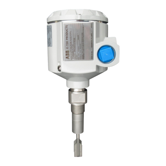
RS85
Vibrating fork level switch
Introduction
This operating instruction manual provides the
following information:
• installation
• setup
• time delay
• troubleshooting
K–TEK Level products
Measurement made easy
Advertisement

Related Manuals for ABB RS85


Summary of Contents for ABB RS85
- Page 1 A B B M E A S U R E M E N T & A N A LY T I C S | O P E R AT I N G I N S T R U C T I O N | O I/ R S 8 5 – E N R E V. K RS85 Vibrating fork level switch K–TEK Level products...
-
Page 2: Table Of Contents
ABB RMA form . . . . . . . . . . . . . . . . . . . -
Page 3: Description
Description Introduction Dimensions 111 mm The RS85 switch is a vibrating fork switch designed for liquid (4⅜ in) level detection. The robust sensor design and built–in temperature compensation ensure reliable response even in the presence of very extreme process conditions. The LED indicators of the RS85 modular electronics allow for simple 19.05 mm (¾... - Page 4 RS85 dual compartment housing and custom RS85 RS85 insertion length The RS85 can be used for level detection in tanks, vessels or switches switches mounted in mounted in KM26 piping containing all types of hot or cold liquids and is...
-
Page 5: Installation
If necessary clean the label using a cloth soaked with either water or isopropyl alcohol. Switch point Tank mounting The RS85 can be mounted for high or low level detection using a flange or the standard ¾ in NPT connection. Switch point and mounting position Bottom mounted Switch points on the sensor depend on the mounting position. - Page 6 Extended Probe Lengths (PL) The sensor length 'PL' for the RS85 will differ based on the process connection. A threaded sensor PL is measured from the bottom process thread to the tip of the fork tine. A...
- Page 7 Mounting positions for low viscosity liquids are shown below. accurate, repeatable service. With high viscosities, the If the RS85 fork is nozzle mounted with a flange and does not optimum mounting is vertical from the vessel top or extend beyond the wall of the vessel, a minimum nozzle horizontal (flush mounted from the side).
- Page 8 NOTE • probe is located near a material fill line. A) All field wiring connected to the RS85 switch must comply with applicable National Electric Code or If any of the above statements apply to your application, do applicable guidelines.
- Page 9 RS8 5 V I BR ATI N G FOR K LE VE L SW ITC H | O I/RS 8 5-E N RE V. K . . .Installation Installation requirements (Ex d): Markings The RS85 is intended for mounting in the boundary of a zone K-TEK PRODUCTS 0 and zone 1 hazardous area When the HT6 – High temperature extension option is used...
-
Page 10: Setup
Power requirement Figure 19 Setup of the RS85 may be achieved using a (1) magnet (provided with switch) positioned on the housing or (2) by means of the pushbuttons on the module. In the following operations, pushbuttons (Figure 19) will correspond to... - Page 11 RS8 5 V I BR ATI N G FOR K LE VE L SW ITC H | O I/RS 8 5-E N RE V. K . . .Setup (configuring switch) Factory default settings/reset Each RS85 will be supplied with the following factory default settings: Fail safe mode = high...
- Page 12 RS 8 5 V I BR ATI N G FOR K LE VE L SWITC H | O I/RS 8 5-E N R EV. K . . .Setup (configuring switch) Table 2 – Fail safe/relay operation Relay state (led) Fail safe Dry fork Wet fork Low level switch (fail safe...
-
Page 13: Time Delay
'S1' position (see figure 26). The time delay will be set and the RS85 will In typical applications, the RS85 in default settings will return to normal operation. If a time delay is not selected, the... -
Page 14: Troubleshooting
Resonator sample applications Thick heavy foam, very turbulent conditions, Set time delay Sporadic foaming liquid faulty RS85 dual switching Extreme RFI Use shielded cable RS85 compartment RS85 Remove water, screw cover and switches housing and custom... -
Page 15: Warranty Statement
THE MAXIMUM EXTENT PERMITTED BY LAW. NO PERSON OR REPRESENTATIVE IS AUTHORIZED TO EXTEND ANY OTHER ABB Inc, K–TEK Products, will repair or replace, at ABB Inc, K– WARRANTY OR CREATE FOR ABB INC, K–TEK PRODUCTS, ANY TEK Product’s, election, defective items which are returned to OTHER LIABILITY IN CONNECTION WITH THE SALE OF ABB ABB Inc, K–TEK Products, by the original purchaser within the... -
Page 16: Abb Rma Form
Be sure to include the Return Authorization (RA) number on the shipping label or package to the attention: Customer Ser- vice. A copy of this document should also be included with the packing list. ABB wants to maintain a safe work environment for its employees. - Page 17 RS8 5 V I BR ATI N G FOR K LE VE L SW ITC H | O I/RS 8 5-E N RE V. K Notes...
- Page 18 RS 8 5 V I BR ATI N G FOR K LE VE L SWITC H | O I/RS 8 5-E N R EV. K Notes...
- Page 19 RS8 5 V I BR ATI N G FOR K LE VE L SW ITC H | O I/RS 8 5-E N RE V. K Notes...
- Page 20 We reserve the right to make technical changes or modify the contents of this document without prior notice. With regard to purchase orders, the agreed particulars shall prevail. ABB does not accept any responsibility whatsoever for potential errors or possible lack of information in this document.