
Related Manuals for Huawei RTN 905 V100


Summary of Contents for Huawei RTN 905 V100
- Page 1 RTN 905 V100 IDU Quick Installation Guide (Indoor) Issue: 01 Date: 2018-10-30 HUAWEI TECHNOLOGIES CO., LTD.
- Page 2 Notice The purchased products, services and features are stipulated by the contract made bet ween Huawei and the customer. All or part of the products, services and features described in this document may not be within the purchase scope or the usage scope. Unless otherwise specified in the contract, all statements, information, and recommendations in this document are provided "AS IS"...
- Page 3 Installation Process Start Before You Start Page 2 Precautions Precautions for Page 3 Handling Pow er Cables Precautions for Handling RTN 905 Page 4 1A/1C/1E IF Jumpers Pages Installing Pow er and IF Cables 18 to 19 Cables Precautions f or Handling Page 19 Installing E1 Cables Page 5...
- Page 4 Commissioning Process Start Pow ering On the Page 30 Equipment Configuring NE Data Page 31 (Using the Web LCT) Configuring NE Data Page 31 (Using the Hand-Held Tool) Pages Aligning Single- 32 to 33 Polarized Antennas Pages Aligning Antennas 32 to 34 Pages 33 Aligning Dual- to 34...
- Page 5 Precautions This document provides guidelines for quick hardware installation. This document does not describe assembly of equipment prior to delivery; it only describes procedures for onsite installation. CAUTION Power Supply The equipment uses a -48 V/-60 V DC power supply. An AC power supply or a high-voltage power supply may cause equipment damage or even human injuries and therefore is forbidden.
- Page 6 Precautions for Handling Power Cables Prior to installing power cables on the RTN 905, confirm that the following conditions are met. The ground point on the column of the cabinet or the indoor ground bar is properly grounded. The power cables are connected correctly to the positive and negative terminals of the power supply device. If a power cable is connected to the positive terminal of the RTN 905 and the negative terminal of the power supply device, there will be a short circuit that damages the power cable and devices.
- Page 7 Precautions for Handling RTN 905 1A/1C/1E IF Jumpers and IF Cables Power off the RTN 905 1A/1C/1E before you remove or connect an IF jumper on the IDU. Do not remove or connect any IF jumper while the RTN 905 1A/1C/1E is powered on. Power off the RTN 905 1A/1C/1E before you remove or connect an IF cable on the ODU.
- Page 8 Precautions for Handling the RTN 905 2A/2E Toggle Lever Switch Position and Description of the Toggle Lever Switch O: OFF You must first pull out the toggle lever switch before turning it. I: ON OptiX RTN 905 ODU-1 LINK1 L/A5 ODU-2 STAT NMS/COM...
- Page 9 Precautions for Handling RTN 905 2A/2E/2F IF Jumpers Do not remove or install an IF jumper connected to Power off the ODU before you remove or install an the ODU while the ODU is powered on. IF jumper connected to the ODU. To cut off the power supply to the ODU of the RTN 905 2F, perform related operations on the NMS.
- Page 10 Installation Tools Measuring tape Level Phillips screwdriver Flat-head screwdriver Ladder Adjustable w rench Bayonet w rench Socket w rench Torque w rench Hex key Combination pliers Needle-nose pliers Diagonal pliers Wire clippers Claw hammer Waterproof Utility knife File Multimeter insulation tape PVC tape ESD gloves Marker...
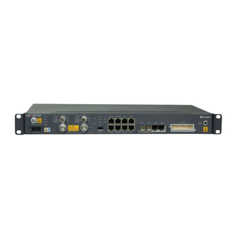
- Page 11 Introduction to the IDU 905 Equipment Ports Ports on the IDU 905 1A OptiX RTN 905 LINK L/A5 STAT NMS/COM CLK/TOD/MON L/A6 TDMA TDMB PWRA E1(1~16) PWRB NEGA RTNA NEGB RTNB -48V -60V EXT/S1 ALMI/ALMO OUT IN OUT IN Status indicators of NE cascading FE/GE service electrical Ground screw...
- Page 12 NE status indicator serial port strap Ports on the IDU 905 1E OptiX RTN 905 CLK/TOD/MON NMS/COM L/A5 STAT WARNING HUAWEI -48V OUTPUT L/A6 TURN OFF POWER BEFORE DISCONNECTING IF CABLE LINK PWRA STAT PWRB NEGA RTNA NEGB RTNB 1—COMBO—2 1—STM-1—2...
- Page 13 Introduction to the IDU 905 Equipment Ports Ports on the IDU 905 2E OptiX RTN 905 CLK/TOD/MON GE1/P1 GE2/P2 NMS/COM ODU2 ODU1 L/A5 STAT LINK1 HUAWEI L/A6 ACT1 PWRA PULL PULL LINK2 STAT PWRB NEGA RTNA NEGB RTNB ACT2 1—COMBO—2 1—STM-1—2...
- Page 14 Installing the IDU 905 Installing the Chassis in a 19-Inch Cabinet Fix the floating nuts. Floating nut Mounting hole When you fix the floating nuts, ensure a space of at least 25 mm for heat dissipation on the left and right sides of the IDU 905. Remove the ground screw.
- Page 15 Install the chassis in the cabinet. Install the PGND cable. To a ground point on the cabinet column or to the indoor ground bar Secure the PGND cable with the ground screw. 1.4±0.14 N· M 2.0±0.2 N· M Installing the Chassis in an ETSI Cabinet Fix the floating nuts.
- Page 16 Install the chassis in the cabinet. Install the PGND cable. To a ground point on the cabinet column or to the indoor ground bar Secure the PGND cable with the ground screw. 2.0±0.2 N· M 1.4±0.14 N· M Installing the Chassis in a 23-Inch Cabinet Remove the mounting ears.
- Page 17 Install the chassis in the cabinet. Install the PGND cable. To a ground point on the cabinet column or to the indoor ground bar Secure the PGND cable with the ground screw. 1.4±0.14 N· M 2.0±0.2 N· M Wall Mounting the Chassis Remove the mounting ears.
- Page 18 Drill holes in the wall. Hold the chassis against the wall and mark the drilling positions. Drill holes and insert bolts into the holes. Ensure a space of at least 50 mm for heat dissipation above and below the IDU. ≥300 mm Drill Ф8 holes 52 to 60 mm deep.
- Page 19 Desk Mounting the Chassis Install the base plates. Install the PGND cable. Remove the mounting ears and install the base plates. Secure the PGND cable with the ground screw. PGND cable 1.4±0.14 N· M Base plate Do not place any objects that may impede heat dissipation next to the chassis.
- Page 20 Secure the E1 Panel. Install the PGND cable for the E1 panel. To a ground point on the cabinet column or to the indoor ground bar...
- Page 21 Installing IDU Cables Install power cables. See appendix "Connecting Cables to a Power Cable Connector." 0.22±0.03 N· M Insert the power cables into the DC connector based on the pin assignment. Y ou do not need to prepare the power cables on sit e if they were prepared bef ore deliv ery .
- Page 22 Confirm that the circuit breaker of the PDU is switched to the off position. Insert the DC connector into the power port on the chassis. Confirm that the two groups of power cables are connected to different power modules. Secure the DC connector with bolts. M2.5 0.4-0.5 N·...
- Page 23 Install fibers. Precautions Always wear protective glasses or goggles when you look directly at an optical port. (Figure 1) Coil fibers from other sites on the ODF and connect them to the local cabinet. Do not coil the fibers from other equipment rooms inside the local cabinet.
- Page 24 Install fibers. Install Ethernet service cables. Install Ethernet service cables. To an Ethernet device Ethernet ports on the RTN 905 support the MDI/MDI-X adaptation function. Either crossover or straight- through network cables can be used to connect the Ethernet ports. Straight-through cables are recommended.
- Page 25 Install IF cables. Install IF jumpers. N type (5/8"), 0.8 to 1.1 N/M For the RTN 905 1A/1C/1E, power off the IDU before you install IF jumpers. For the RTN 905 2A/2E, power off the ODU before you install IF jumpers. If RG-8U or 1/2-inch IF cables are used, use IF jumpers to connect IF cables and the IDU.
- Page 26 RTN 905 1C Installing XPIC cables X-OUT X-IN RTN 905 1E/1C OptiX RTN 905 NMS/COM CLK/TOD/MON L/A5 STAT WARNING HUAWEI -48V OUTPUT L/A6 TURN OFF POWER BEFORE DISCONNECTING IF CABLE LINK PWRA STAT PWRB NEGA RTNA NEGB RTNB 1—COMBO—2 1—STM-1—2...
- Page 27 The RTN 905 2F provides three 10GE COMBO ports to achieve 1+1, XPIC, EPLA, and TDM functions. RTN 905 1E COMBO-1 OptiX RTN 905 NMS/COM CLK/TOD/MON L/A5 STAT WARNING HUAWEI -48V OUTPUT L/A6 TURN OFF POWER BEFORE DISCONNECTING IF CABLE LINK PWRA STAT PWRB NEGA RTNA NEGB RTNB 1—COMBO—2...
- Page 28 Installing NMS Cables Install an NMS cable on a gateway NE. NMS/COM Install NMS cables on multiple NEs at one site. NMS/COM OptiX RTN 905 ODU-1 LINK1 L/A5 ODU-2 STAT NMS/COM CLK/TOD/MON ACT1 L/A6 PULL PULL LINK2 TDMA TDMB PWRA ACT2 PWRB NEGA...
- Page 29 Preparing and Installing External Alarm Cables Make an external alarm cable based on pin assignments. Pin Assignments for External Alarm Cables Color Relationship Function White/Orange First alarm signal input Twisted pair Ground of first alarm Orange signal input Pin 8 Second alarm Pin 1 White/Green...
- Page 30 Preparing and Installing Asynchronous Data Cables Make an asynchronous data cable according to the pin assignment. Pin 8 Pin 8 Pin 1 Pin 1 Pin assignments for Asynchronous Data Cables Relationship Color Function Positive for transmitting data by the NMS White/Orange cascading port Twisted pair...
- Page 31 Preparing and Installing External Clock Cables Make an external clock cable based on pin assignments. Pin 8 Pin 1 Pin 8 Pin 1 Pin assignments for External Clock Cables External Time Input External Time Output External Time Input External Time Output Color Relationship External Clock...
-
Page 32: Cable Connections
Cable connections OptiX RTN 905 LINK1 L/A5 NMS/COM C L K / T O D / M O N STAT HUAWEI L/A6 PWRA TDMA TDMB N E G A R T N A N E G B R T N B... - Page 33 Powering On the Equipment Before powering on the equipment, ensure that • The installation of the ODU, IF jumpers, and IF cables is complete. • You are familiar with the precautions for handling power cables. • The ODU power switches on the IDU of the RTN 905 2A/2E are turned off. STAT PWRA PWRB...
- Page 34 Configuring NE Data (Using the Web LCT) Connect the NMS/COM port to the PC where the Web LCT is running. NMS/COM You can use the Web LCT to configure NE data, including basic NE data, IF/ODU information for the radio links, and parameters for IF and ODU ports.
- Page 35 Aligning Antennas Aligning Single-Polarized Antennas Use the installation positions and heights of local and remote antennas to determine their azimuths. Adjust the pitch angles of the antennas to the horizontal position. Connect a multimeter to the received signal strength indicator (RSSI) port on the ODU at the local end and measure the voltage value V The red line of the multimeter is connected to the core of the RSSI port, and the black line is connected to the ground pin.
- Page 36 Front view of the tracking lines at different RSL values of each line 天线不同仰角下扫描路径的正面图 各路径信号值 elevation angles for the antenna Loosen/Tighten the elevation adjustment screw to turn the local antenna vertically. Adjust the pitch angle until the RSL reaches the peak within the tracked range. Repeat Steps 3 to 4 to ensure that three signal peaks are tracked both horizontally and vertically.
- Page 37 Use a multimeter to measure the RSL (P1) on the RSSI port of the horizontally-polarized ODU at the local end. Power on the vertically-polarized ODU at the local end. Use a multimeter to measure the RSL on the RSSI port of the vertically-polarized ODU.
-
Page 38: Checking The Installation
Checking the Installation What to Check For The chassis is installed securely in the position specified in the engineering design documents. If the cabinet door is closed, the door should not press against the chassis or any cables. Chassis components have no paint spatters, damage, or stains. Re-paint or clean components, as required. - Page 39 Appendix Connecting Cables to a Power Cable Connector Obtaining Tools, Cables, and a Power Cable Connector Tw o 0 V black ground cables Tw o -48 V blue pow er cables Pow er cable connector Ruler Diagonal pliers Utility knife Flat-head screwdriver Peeling Cables...
- Page 40 Appendix Connecting Cables to a Power Cable Connector Connecting Cables to the Power Cable Connector Route a cable into the pow er cable connector. Power Cable Cable Connector Terminal -48 V power cable (blue) 0 V ground cable (black) -48 V power cable (blue) 0 V ground cable (black) Fasten the cable.
- Page 41 Appendix Installing the MN1 Subboard Remove the filler panel from the slot for the MN1 subboard. Install the MN1 subboard. Screw the MN1 subboard.
- Page 42 HUAWEI TECHNOLOGIES CO., LTD. Huawei Industrial Base Bantian Longgang Shenzhen 518129 People’s Republic of China www.huawei.com...