
Related Manuals for Huawei FusionServer Pro CH121 V5


Summary of Contents for Huawei FusionServer Pro CH121 V5
- Page 1 FusionServer Pro CH121 V5 Compute Node V100R005 User Guide Issue Date 2019-08-10 HUAWEI TECHNOLOGIES CO., LTD.
- Page 2 Notice The purchased products, services and features are stipulated by the contract made between Huawei and the customer. All or part of the products, services and features described in this document may not be within the purchase scope or the usage scope. Unless otherwise specified in the contract, all statements, information, and recommendations in this document are provided "AS IS"...
-
Page 3: About This Document
FusionServer Pro CH121 V5 Compute Node User Guide About This Document About This Document Purpose This document describes the CH121 V5 compute node (CH121 V5) in terms of its components, common operations, basic configuration, hardware installation, troubleshooting, software and configuration utilities, electrostatic discharge (ESD) prevention, and product specifications. - Page 4 FusionServer Pro CH121 V5 Compute Node User Guide About This Document Symbol Description Calls attention to important information, best practices and tips. NOTE is used to address information not related to personal injury, equipment damage, and environment deterioration. Change History...
-
Page 5: Table Of Contents
FusionServer Pro CH121 V5 Compute Node User Guide Contents Contents About This Document........................ii 1 Overview............................1 1.1 Overview..................................1 1.2 Physical Structure................................3 1.3 Logical Structure ................................4 2 Hardware Description........................5 2.1 Front Panel..................................5 2.1.1 Appearance.................................. 5 2.1.2 Indicators and Buttons..............................6 2.1.3 Ports..................................... - Page 6 FusionServer Pro CH121 V5 Compute Node User Guide Contents 3.1 Power-Off Procedure..............................26 3.2 Power-On Procedure..............................27 3.3 Removing a CH121 V5..............................28 3.4 Installing a CH121 V5..............................31 3.5 Removing the Cover..............................35 3.6 Installing the Cover..............................35 3.7 Removing the Air Ducts............................... 36 3.8 Installing the Air Duct..............................
- Page 7 FusionServer Pro CH121 V5 Compute Node User Guide Contents 4.3.7.5 Selecting a Language..............................90 4.3.7.6 Restarting the Compute Node..........................91 4.3.8 Installing an OS................................. 91 5 Optional Part Installation......................93 5.1 Precautions..................................93 5.2 Optional Parts................................93 5.2.1 Installing an M.2 FRU............................... 93 5.2.2 Installing the Screw-in RAID Controller Card......................95...
- Page 8 FusionServer Pro CH121 V5 Compute Node User Guide Contents 12.6 Managing the E9000 Server Using the Local KVM....................146 12.6.1 Logging In to the MM910 CLI..........................146 12.6.2 Logging In to the Operating System of a Compute Node..................147 12.6.3 Mounting the DVD Drive to a Compute Node......................148 12.6.4 Logging In to a Compute Node or a Switch Module over SOL................149...
-
Page 9: Overview
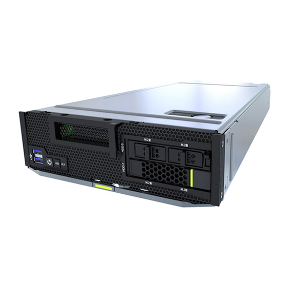
FusionServer Pro CH121 V5 Compute Node User Guide 1 Overview Overview 1.1 Overview 1.2 Physical Structure 1.3 Logical Structure 1.1 Overview ® ® The CH121 V5 is a half-width compute node powered by Intel Xeon Scalable processors. It delivers supreme computing power, large memory capacity, and outstanding scalability. - Page 10 FusionServer Pro CH121 V5 Compute Node User Guide 1 Overview Figure 1-1 CH121 V5 Issue 06 (2019-08-10) Copyright © Huawei Technologies Co., Ltd.
-
Page 11: Physical Structure
FusionServer Pro CH121 V5 Compute Node User Guide 1 Overview 1.2 Physical Structure Figure 1-2 CH121 V5 physical structure (Optional) HHHL PCIe riser (Optional) HHHL PCIe card module (Optional) M.2 SSDs (Optional) USB flash drive (Optional) TPM Screw-in RAID controller... -
Page 12: Logical Structure
FusionServer Pro CH121 V5 Compute Node User Guide 1 Overview l a: The drive slots support 2.5-inch SAS/SATA/NVMe drives and M.2 modules and mixed configuration of them. l b: An M.2 module is a 2.5-inch drive module that consists of one M.2 adapter and two M.2 FRUs. -
Page 13: Hardware Description
FusionServer Pro CH121 V5 Compute Node User Guide 2 Hardware Description Hardware Description 2.1 Front Panel 2.2 Processor 2.3 Memory 2.4 Storage 2.5 Network 2.6 I/O Expansion 2.7 Boards 2.1 Front Panel 2.1.1 Appearance Figure 2-1 Front view (with an M.2 module) Issue 06 (2019-08-10) Copyright ©... -
Page 14: Indicators And Buttons
FusionServer Pro CH121 V5 Compute Node User Guide 2 Hardware Description Slide-out label plate (with an PCIe panel SN label) Ejector release button Ejector lever Model 2.5" drive M.2 FRU M.2 adapter M.2 module l a: The drive slots support 2.5-inch SAS/SATA/NVMe drives and M.2 modules and mixed configuration of them. - Page 15 FusionServer Pro CH121 V5 Compute Node User Guide 2 Hardware Description Description Table 2-1 Indicators and buttons on the front panel Silkscreen Indicator/ Description Button Power button/ Power indicator: indicator l Off: The device is not powered on. l Steady yellow: The device is powered on.
-
Page 16: Ports
FusionServer Pro CH121 V5 Compute Node User Guide 2 Hardware Description 2.1.3 Ports Port Positions Figure 2-3 Ports on the front panel USB 3.0 ports Port Description Port Type Quantity Description USB port USB 3.0 Used to connect to a USB device. -
Page 17: Processor
The server supports one or two processors. If only one processor is required, install it in socket CPU1. The same model of processors must be used in a server. Contact your local Huawei sales representative or use the Intelligent Computing Compatibility Checker to determine the components to be used. -
Page 18: Memory
FusionServer Pro CH121 V5 Compute Node User Guide 2 Hardware Description Figure 2-5 Processor positions 2.3 Memory 2.3.1 Memory Identifier You can determine the memory module properties based on the label attached to the memory module. Figure 2-6 Memory identifier Issue 06 (2019-08-10) Copyright ©... -
Page 19: Memory Subsystem Architecture
FusionServer Pro CH121 V5 Compute Node User Guide 2 Hardware Description callout Description Definition Capacity of the memory module. l 8 GB l 16 GB l 32 GB l 64 GB l 128 GB Number of ranks of the memory l 1R: single-rank module. -
Page 20: Memory Compatibility
FusionServer Pro CH121 V5 Compute Node User Guide 2 Hardware Description Memory Channel Memory Slot 1C (primary) DIMM020(1C1) DIMM021(1C2) 1D (primary) DIMM030(1D1) DIMM031(1D2) 1E (primary) DIMM040(1E1) DIMM041(1E2) 1F (primary) DIMM050(1F1) DIMM051(1F2) CPU 2 2A (primary) DIMM100(2A1) DIMM101(2A2) 2B (primary) DIMM110(2B1) - Page 21 Maximum operating speed of a memory module l The DDR4 memory modules of different types (RDIMM and LRDIMM) cannot be used together. l Contact your local Huawei sales representative or use the Intelligent Computing Compatibility Checker to determine the components to be used.
- Page 22 FusionServer Pro CH121 V5 Compute Node User Guide 2 Hardware Description Observe the following rules when you need to use different types of memory modules in a compute node: – RDIMMs and LRDIMMs cannot be used together. – Do not use 128 GB memory modules together with memory modules of other capacities.
-
Page 23: Memory Installation Guidelines
FusionServer Pro CH121 V5 Compute Node User Guide 2 Hardware Description Parameter Specifications l a: If the Cascade Lake processor is used, the rated speed and maximum operating speed of the RDIMM can reach 2933 MT/s. If the Skylake processor is used, the rated speed and maximum operating speed of a DDR4 memory module can reach 2666 MT/s only. - Page 24 FusionServer Pro CH121 V5 Compute Node User Guide 2 Hardware Description Figure 2-7 Memory slots Figure 2-8 DDR4 memory installation guidelines (1 processor) Figure 2-9 DDR4 memory installation guidelines (2 processors) Issue 06 (2019-08-10) Copyright © Huawei Technologies Co., Ltd.
-
Page 25: Memory Protection Technologies
3. l a: Only 2.5-inch drives fit into the front slots. l b: Mixed configuration of M.2 modules and SAS/SATA/NVMe drives is supported. l Contact your local Huawei sales representative or use the Intelligent Computing Compatibility Checker to determine the components to be used. -
Page 26: Drive Indicators
FusionServer Pro CH121 V5 Compute Node User Guide 2 Hardware Description Figure 2-10 Drive numbering M.2 FRU Figure 2-11 Drive numbering 2.4.3 Drive Indicators SAS/SATA Drive Indicators Figure 2-12 SAS/SATA drive indicators Table 2-5 Description of SAS/SATA drive indicators Green Indicator... - Page 27 FusionServer Pro CH121 V5 Compute Node User Guide 2 Hardware Description M.2 FRU Indicators Figure 2-13 M.2 FRU indicators Table 2-6 M.2 FRU indicator description Indicator Description M.2 FRU fault indicator l Off: The M.2 FRU is running properly. l Blinking yellow: The M.2 FRU is being located, or RAID is being rebuilt.
-
Page 28: Raid Controller Card
The NVMe SSD is faulty. 2.4.4 RAID Controller Card The RAID controller card supports RAID configuration, RAID level migration, and drive roaming. Contact your local Huawei sales representative or use the Intelligent Computing Compatibility Checker to determine the components to be used. -
Page 29: I/O Expansion
FusionServer Pro CH121 V5 Compute Node User Guide 2 Hardware Description to the Base network ports of the switch modules in slots 2X and 3X. The LOM supports Wake on LAN (WOL) and PXE functions. Figure 2-15 Connections between the LOM and I/O modules... -
Page 30: Pcie Slot Description
FusionServer Pro CH121 V5 Compute Node User Guide 2 Hardware Description Contact your local Huawei sales representative or use the Intelligent Computing Compatibility Checker to determine the components to be used. 2.6.2 PCIe Slot Description NOTE The PCIe slots mapping to a vacant CPU socket are unavailable. -
Page 31: Boards
FusionServer Pro CH121 V5 Compute Node User Guide 2 Hardware Description PCIe Displ PCIe Conne Port Slot Slot ay on Stand ctor Width Size ards Width l The B/D/F (Bus/Device/Function Number) is the default value when the server is fully configured with PCIe devices. - Page 32 FusionServer Pro CH121 V5 Compute Node User Guide 2 Hardware Description Memory slots CPU 2 OPA sideband signal port Drive backplane connector Drive cage HLY indicator UID button/indicator Power button/indicator USB 3.0 ports Issue 06 (2019-08-10) Copyright © Huawei Technologies Co., Ltd.
-
Page 33: Basic Operations
FusionServer Pro CH121 V5 Compute Node User Guide 3 Basic Operations Basic Operations 3.1 Power-Off Procedure 3.2 Power-On Procedure 3.3 Removing a CH121 V5 3.4 Installing a CH121 V5 3.5 Removing the Cover 3.6 Installing the Cover 3.7 Removing the Air Ducts 3.8 Installing the Air Duct... -
Page 34: Power-Off Procedure
FusionServer Pro CH121 V5 Compute Node User Guide 3 Basic Operations 3.1 Power-Off Procedure NOTE l Powering off a compute node will interrupt all services and programs running on it. Therefore, before powering off a compute node, ensure that all services and programs have been stopped or migrated to other compute nodes. -
Page 35: Power-On Procedure
FusionServer Pro CH121 V5 Compute Node User Guide 3 Basic Operations Figure 3-1 Power Control Step 5 Select the compute node to be powered off, and click Normal Power Off. The selected compute node will be powered off. NOTE To power off all compute nodes at a time, select the check box in the header row and click Normal Power Off. -
Page 36: Removing A Ch121 V5
FusionServer Pro CH121 V5 Compute Node User Guide 3 Basic Operations For details, see MM910 Management Module V100R001 User Guide. – On the MM910 CLI, run the following command: powerstate For details, see MM910 Management Module V100R001 Command Reference. The following describes how to power on a compute node using the MM910 WebUI. - Page 37 FusionServer Pro CH121 V5 Compute Node User Guide 3 Basic Operations Figure 3-3 Positions and slot numbers of the CH121 V5 compute nodes Step 2 Power off the compute node. For details, see 3.1 Power-Off Procedure. Step 3 Remove the compute node.
- Page 38 FusionServer Pro CH121 V5 Compute Node User Guide 3 Basic Operations Figure 3-4 Removing a compute node Step 4 Place the removed compute node in an ESD bag. Place only one compute node in an ESD bag. Step 5 Install filler panels.
-
Page 39: Installing A Ch121 V5
FusionServer Pro CH121 V5 Compute Node User Guide 3 Basic Operations Figure 3-5 Installing a filler panel ----End 3.4 Installing a CH121 V5 Procedure Step 1 Determine the position of the compute node in the chassis. Issue 06 (2019-08-10) Copyright © Huawei Technologies Co., Ltd. - Page 40 FusionServer Pro CH121 V5 Compute Node User Guide 3 Basic Operations Figure 3-6 Positions and slot numbers of the CH121 V5 compute nodes Step 2 Remove filler panels. NOTE Perform this operation only when filler panels are installed. Press and hold the groove inward on the filler panel to release the filler panel. See (1) in Figure 3-7.
- Page 41 FusionServer Pro CH121 V5 Compute Node User Guide 3 Basic Operations Figure 3-7 Removing a filler panel Place the removed filler panel in an accessory recycle bin. Step 3 Install the compute node. To prevent device damage or personal injury, hold the bottom of the device with both hands when installing it.
- Page 42 FusionServer Pro CH121 V5 Compute Node User Guide 3 Basic Operations Figure 3-8 Installing a partition board Press the ejector release button on the compute node. See (1) in Figure 3-9. Fully open the ejector lever. See (2) in Figure 3-9.
-
Page 43: Removing The Cover
FusionServer Pro CH121 V5 Compute Node User Guide 3 Basic Operations 3.5 Removing the Cover Procedure Step 1 Power off the compute node. For details, see 3.1 Power-Off Procedure. Step 2 Remove the compute node. For details, see 3.3 Removing a CH121 Step 3 Place the compute node on the ESD workstation. -
Page 44: Removing The Air Ducts
FusionServer Pro CH121 V5 Compute Node User Guide 3 Basic Operations Aligning the notches on the cover with the nail heads on the chassis base, vertically place the cover onto the compute node. See (1) in Figure 3-11. Push the cover towards the front panel of the compute node until the cover clicks into place. -
Page 45: Installing The Air Duct
FusionServer Pro CH121 V5 Compute Node User Guide 3 Basic Operations Step 6 Lift the left and right air ducts. Figure 3-12 Removing the air ducts Step 7 Place the removed component in an ESD bag. ----End 3.8 Installing the Air Duct Procedure Step 1 Power off the compute node. - Page 46 FusionServer Pro CH121 V5 Compute Node User Guide 3 Basic Operations A transformed air duct cannot be used in compute nodes without PCIe cards any more. Please exercise caution. Split the left air duct along the dotted line. Figure 3-13 Transforming the air duct Step 9 Align the right air duct with the right DIMMs, align the left air duct with the left DIMMs and heat sinks, and vertically place the air ducts downwards.
-
Page 47: Removing The Pcie Card Panel
FusionServer Pro CH121 V5 Compute Node User Guide 3 Basic Operations Step 10 Install the cover. For details, see 3.6 Installing the Cover. Step 11 Install the compute node. For details, see 3.4 Installing a CH121 Step 12 Power on the compute node. -
Page 48: Installing The Pcie Card Panel
FusionServer Pro CH121 V5 Compute Node User Guide 3 Basic Operations Step 7 Place the removed component in an ESD bag. ----End 3.10 Installing the PCIe Card Panel Procedure Step 1 Power off the compute node. For details, see 3.1 Power-Off Procedure. -
Page 49: Removing A Pcie Card
FusionServer Pro CH121 V5 Compute Node User Guide 3 Basic Operations Figure 3-16 Installing a PCIe card panel Step 10 Install the cover. For details, see 3.6 Installing the Cover. Step 11 Install the compute node. For details, see 3.4 Installing a CH121 Step 12 Power on the compute node. - Page 50 FusionServer Pro CH121 V5 Compute Node User Guide 3 Basic Operations Step 6 Determine the position of the PCIe card. Figure 3-17 Position of the PCIe card Step 7 Remove the PCIe card. Loosen the three screws that secure the PCIe card bracket, and vertically lift the PCIe card bracket.
-
Page 51: Installing A Pcie Card
FusionServer Pro CH121 V5 Compute Node User Guide 3 Basic Operations Figure 3-18 Removing a PCIe card Step 8 Place the removed component in an ESD bag. Step 9 Install the PCIe card front panel. For details, see 3.10 Installing the PCIe Card Panel. - Page 52 FusionServer Pro CH121 V5 Compute Node User Guide 3 Basic Operations Step 5 Remove the air duct. For details, see 3.7 Removing the Air Ducts. Step 6 Remove the PCIe card front panel. For details, see 3.9 Removing the PCIe Card Panel.
- Page 53 FusionServer Pro CH121 V5 Compute Node User Guide 3 Basic Operations Figure 3-20 Installing a PCIe card Step 10 Install the air duct. For details, see 3.8 Installing the Air Duct. Step 11 Install the cover. For details, see 3.6 Installing the Cover.
-
Page 54: Removing A Sas/Sata Drive
FusionServer Pro CH121 V5 Compute Node User Guide 3 Basic Operations 3.13 Removing a SAS/SATA Drive NOTE l The SATA or SAS drives support hot swap. If the drive to be removed has no operating system installed, you can remove it without powering off the compute node. -
Page 55: Installing A Sas/Sata Drive
FusionServer Pro CH121 V5 Compute Node User Guide 3 Basic Operations Step 4 Remove the drive. Press the ejector release button on the drive panel to release the ejector lever. See (1) in Figure 3-22. Open the drive ejector lever completely. See (2) in Figure 3-22. - Page 56 FusionServer Pro CH121 V5 Compute Node User Guide 3 Basic Operations Procedure Step 1 Take the spare part out of its ESD bag. Step 2 Determine the slot and position of the drive. For details, see 2.4.1 Drive Configurations 2.4.2 Drive Numbering.
-
Page 57: Removing An Nvme Drive
FusionServer Pro CH121 V5 Compute Node User Guide 3 Basic Operations Figure 3-24 Installing a drive Step 5 Check the running status of the drive by observing its indicators. For details, see SAS/SATA Drive Indicators. Step 6 Restore the drive data. - Page 58 FusionServer Pro CH121 V5 Compute Node User Guide 3 Basic Operations Step 1 Determine the slot and position of the drive. Figure 3-25 Positions of drives Step 2 Check the running status of the drive by observing its indicators. For details, see NVMe SSD Indicators.
- Page 59 FusionServer Pro CH121 V5 Compute Node User Guide 3 Basic Operations Figure 3-26 Removing a drive Step 5 Place the removed component in an ESD bag. Step 6 Install a drive filler. NOTE Perform this operation only when a drive is not installed immediately.
- Page 60 FusionServer Pro CH121 V5 Compute Node User Guide 3 Basic Operations Figure 3-27 Positions of drives Step 2 Check the running status of the drive by observing its indicators. For details, see NVMe SSD Indicators. Step 3 Determine whether the drive needs to be removed.
- Page 61 VMD function is disabled. The following uses Huawei NVMe drive as an example to describe how to install the NVMe driver hiodriver and NVMe tool NVMe Toolbox. The NVMe Toolbox can be used to query NVMe drive information, upgrade the firmware, and perform hot swap.
- Page 62 FusionServer Pro CH121 V5 Compute Node User Guide 3 Basic Operations Figure 3-29 Viewing running NVMe SSDs Step 6 Select the NVMe drive to be removed. Step 7 Click eject. After the drive is removed, "Eject Succeed" will be displayed.
- Page 63 FusionServer Pro CH121 V5 Compute Node User Guide 3 Basic Operations Step 8 Click OK. Step 9 Observe the indicator status of the NVMe drive. If the green indicator is off and the yellow indicator blinks at 0.5 Hz, remove the NVMe drive slowly.
- Page 64 FusionServer Pro CH121 V5 Compute Node User Guide 3 Basic Operations If no, rectify the drive fault. Step 4 Configure kernel parameters. Log in to the OS, and open /boot/efi/EFI/redhat/grub.cfg (if the OS is installed in UEFI mode) or /boot/grub2/grub.cfg (if the OS is installed in legacy mode).
- Page 65 FusionServer Pro CH121 V5 Compute Node User Guide 3 Basic Operations Figure 3-35 Checking the configuration If SUSE 12.2 is installed in UEFI: Run the cat /proc/cmdline command. If the command output does not contain "pciehp.pciehp_force=1 pci=pcie_bus_perf", you need to configure kernel parameters.
- Page 66 FusionServer Pro CH121 V5 Compute Node User Guide 3 Basic Operations Run the cat /proc/cmdline command. If the command output contains "pciehp.pciehp_force=1 pci=pcie_bus_perf", the kernel is configured successfully. Figure 3-39 Checking the configuration Step 5 Upgrade the OS kernel. Example 1: RHEL 7.3 Upgrade the kernel of RHEL 7.3 to kernel-3.10.0-514.26.2.e17.x86_64 or later to...
- Page 67 FusionServer Pro CH121 V5 Compute Node User Guide 3 Basic Operations Run the rpm -ivh kernel-default-4.4.74-92.32.1.x86_64.rpm command to upload the upgrade package to the OS for installation. Figure 3-43 Installing the upgrade package Restart the OS after the installation is complete.
- Page 68 -xxx -s 85:03.0 Figure 3-45 Querying the original register value NOTE If the default a8 register value is not f1, contact Huawei technical support. Change the value of the a8 register to e1. setpci -s <B/D/F> a8.B=e1 <B/D/F>: indicates the root port (B/D/F) of the NVMe drive. For details about the...
- Page 69 FusionServer Pro CH121 V5 Compute Node User Guide 3 Basic Operations Stop accessing the NVMe drive. Stop I/O operations on the NVMe drive to be removed and unmount any file systems mounted to the drive. If the drive is used by the mdadm utility, you also need to set the drive to the fail state.
-
Page 70: Installing An Nvme Drive
FusionServer Pro CH121 V5 Compute Node User Guide 3 Basic Operations NOTE If the value of the register is not restored to the original one, the orderly hot insertion of the NVMe drives may be abnormal. Step 8 Install a drive filler. - Page 71 FusionServer Pro CH121 V5 Compute Node User Guide 3 Basic Operations Figure 3-48 Positions of drives Step 3 Remove the drive filler. NOTE Perform this operation only when a drive filler is installed. Step 4 Install the driver for NVMe drives.
- Page 72 NOTE – It is recommended that you install the latest driver. – If Huawei NVMe driver is installed on a server using both Intel NVMe drives and Huawei NVMe drives, the server cannot identify the Intel NVMe drives. Step 5 Install NVMe drives.
- Page 73 FusionServer Pro CH121 V5 Compute Node User Guide 3 Basic Operations Figure 3-49 Positions of drives Step 3 Remove the drive filler. NOTE Perform this operation only when a drive filler is installed. Step 4 Install the driver for NVMe drives.
- Page 74 NOTE – It is recommended that you install the latest driver. – If Huawei NVMe driver is installed on a server using both Intel NVMe drives and Huawei NVMe drives, the server cannot identify the Intel NVMe drives. Step 5 Install NVMe drives.
- Page 75 FusionServer Pro CH121 V5 Compute Node 3 Basic Operations User Guide "pciehp.pciehp_force=1 pci=pcie_bus_perf" at the end of the sentence. Do not add the content in a new line. Figure 3-51 Configuring kernel parameters (1) Figure 3-52 Configuring kernel parameters (2) Save the file and restart the compute node.
- Page 76 FusionServer Pro CH121 V5 Compute Node 3 Basic Operations User Guide Run the vi /boot/efi/EFI/sles/grub.cfg command. In the command output, find the sentence that is displayed after the cat/proc/cmdline command is executed in Step 5.a.1), and add a space and then "pciehp.pciehp_force=1 pci=pcie_bus_perf"...
- Page 77 FusionServer Pro CH121 V5 Compute Node 3 Basic Operations User Guide Figure 3-58 Kernel version Log in to the official Red Hat website to download the kernel upgrade package (kernel-3.10.0-514.26.2.e17.x86_64.rpm for example). Run the rpm -ivh kernel-3.10.0-514.26.2.e17.x86_64.rpm command to upload the upgrade package to the OS for installation.
- Page 78 FusionServer Pro CH121 V5 Compute Node User Guide 3 Basic Operations Restart the OS after the installation is complete. Run the uname -r command to check the kernel version. If it is still the original kernel version, change the version in the grub.cfg file.
-
Page 79: Installation And Configuration
FusionServer Pro CH121 V5 Compute Node User Guide 4 Installation and Configuration Installation and Configuration 4.1 Installation Environment Requirements 4.2 Hardware Installation 4.3 Initial Configuration 4.1 Installation Environment Requirements 4.1.1 Space and Airflow Requirements To allow for servicing and adequate airflow, observe the following space and airflow requirements: Install the server in an access-restricted area. -
Page 80: Cabinet Requirements
FusionServer Pro CH121 V5 Compute Node User Guide 4 Installation and Configuration Table 4-1 Temperature and humidity requirements in the equipment room Item Description Temperature 5ºC to 35ºC (41ºF to 95ºF) Humidity 8% RH to 90% RH (non-condensing) 4.1.3 Cabinet Requirements A general 19-inch cabinet with a depth of more than 1000 mm (39.37 in.) which... -
Page 81: Unpacking The Compute Node
FusionServer Pro CH121 V5 Compute Node User Guide 4 Installation and Configuration Wait until overheating devices have cooled down before touching them to avoid injury. 4.2.2 Unpacking the Compute Node Procedure Step 1 Check whether the packing case and seals are in good conditions. -
Page 82: Installing Optional Parts
FusionServer Pro CH121 V5 Compute Node User Guide 4 Installation and Configuration Step 4 Take the compute nodes out of the ESD bags and place them separately on the ESD floor. NOTE Take out the compute node only before you install it immediately. -
Page 83: Installing The Compute Node
FusionServer Pro CH121 V5 Compute Node User Guide 4 Installation and Configuration 4.2.4 Installing the Compute Node Procedure Step 1 Install the CH121 V5. For details, see 3.4 Installing a CH121 ----End 4.2.5 Connecting to Network To connect the E9000 to the network, install switch modules for signal management between the compute node and external network. - Page 84 FusionServer Pro CH121 V5 Compute Node User Guide 4 Installation and Configuration User Name User Default User Type User Status Login Descriptio Password Method A user that Admin@900 Administrati Enabled Local login logs in to U- ve User Boot over a serial port.
-
Page 85: Configuration Overview
FusionServer Pro CH121 V5 Compute Node User Guide 4 Installation and Configuration 4.3.2 Configuration Overview Configuration Process Figure 4-5 Initial configuration process Table 4-3 Process description Step Description Change the initial Initial password of the default iBMC user passwords Check the compute node l Ensure that the compute node version meets site requirements. -
Page 86: Changing Initial Passwords
FusionServer Pro CH121 V5 Compute Node User Guide 4 Installation and Configuration Documents Configure the iBMC. The configuration method varies depending on the iBMC version. For details, see FusionServer Pro E9000 Server iBMC User Guide. Configure RAID settings. For details, see... - Page 87 FusionServer Pro CH121 V5 Compute Node User Guide 4 Installation and Configuration Step 3 In the navigation tree, choose Account Management > Node User Management. The Node User Management page is displayed. Figure 4-6 Node User Management page Step 4 Click on the right of the compute node in the specific slot.
-
Page 88: Checking The Compute Node
FusionServer Pro CH121 V5 Compute Node User Guide 4 Installation and Configuration The initial password of the iBMC is changed. ----End 4.3.4 Checking the Compute Node Process Check the compute node by performing the following operations: Figure 4-8 Check process Procedure Step 1 Check the indicators on the panels and ensure that the device is working properly. - Page 89 FusionServer Pro CH121 V5 Compute Node User Guide 4 Installation and Configuration Figure 4-9 Querying version information Pay attention to the following information: – CPLD Version: CPLD version of the compute node – Active iBMC Version: version of the iBMC in the active work space of the compute node –...
-
Page 90: Setting The Ibmc Ip Address
FusionServer Pro CH121 V5 Compute Node User Guide 4 Installation and Configuration For details, see FusionServer Pro E9000 Server V100R001 HMM Alarm Handling. – If no, no further action is required. ----End 4.3.5 Setting the iBMC IP Address Scenarios This section describes how to set the iBMC IP address on the MM910 WebUI. -
Page 91: Configuring Raid
FusionServer Pro CH121 V5 Compute Node User Guide 4 Installation and Configuration Figure 4-11 Setting an IP address for the management network port Click Edit. Edit the iBMC IP address of the compute node in a specific slot. Click Save. -
Page 92: Entering The Bios
FusionServer Pro CH121 V5 Compute Node User Guide 4 Installation and Configuration Process Figure 4-12 Process for configuring the BIOS 4.3.7.1 Entering the BIOS 4.3.7.1.1 Entering the BIOS (Skylake) Procedure Step 1 Log in to the desktop of the compute node. - Page 93 FusionServer Pro CH121 V5 Compute Node User Guide 4 Installation and Configuration Figure 4-13 BIOS startup screen NOTE l To go to the BIOS front page, press F11 or F3. l To boot from the network, press F12. Enter the password in the displayed dialog box.
-
Page 94: Entering The Bios (Cascade Lake)
FusionServer Pro CH121 V5 Compute Node User Guide 4 Installation and Configuration Figure 4-14 Entering the BIOS password Step 6 Enter the BIOS password. NOTE l The default BIOS password is Admin@9000. l Press F2 to alternate between the English (US), French, and Japanese keyboards. - Page 95 FusionServer Pro CH121 V5 Compute Node User Guide 4 Installation and Configuration Step 5 During the restart, press Delete or F4 when the information shown in Figure 4-15 displayed. Figure 4-15 BIOS startup screen NOTE l To go to the Boot Manager screen, press F11 pr F3.
-
Page 96: Setting The System Boot Sequence
FusionServer Pro CH121 V5 Compute Node User Guide 4 Installation and Configuration Figure 4-16 Entering the BIOS password Step 6 Enter the BIOS password. NOTE l The default BIOS password is Admin@9000. l Press F2 to alternate between the English (US), French, and Japanese keyboards. -
Page 97: Setting Pxe For A Nic
FusionServer Pro CH121 V5 Compute Node User Guide 4 Installation and Configuration Step 2 Select Boot Type and press Enter. The Boot Type dialog box is displayed. Step 3 Select Legacy Boot or UEFI Boot, and then press Enter. NOTE l The default boot mode is UEFI. -
Page 98: Setting The Bios Password
FusionServer Pro CH121 V5 Compute Node User Guide 4 Installation and Configuration NOTE MAC information of two network ports can be displayed on the PXE screen. PXE setting is not supported. The PXE function is enabled for the two network ports by default. -
Page 99: Restarting The Compute Node
FusionServer Pro CH121 V5 Compute Node User Guide 4 Installation and Configuration Figure 4-17 Selecting a language Step 3 Select the language to be used and press Enter. The target language is set for the GUI. ----End 4.3.7.6 Restarting the Compute Node After the settings, you need to restart the compute node for the settings to take effect. - Page 100 FusionServer Pro CH121 V5 Compute Node User Guide 4 Installation and Configuration The installation method varies with the operating system. For details, see Huawei Server OS Installation Guide. Issue 06 (2019-08-10) Copyright © Huawei Technologies Co., Ltd.
-
Page 101: Optional Part Installation
FusionServer Pro CH121 V5 Compute Node User Guide 5 Optional Part Installation Optional Part Installation 5.1 Precautions 5.2 Optional Parts 5.1 Precautions Before installing multiple components, read the installation instructions for all the components and identify similar actions to simply the installation process. - Page 102 FusionServer Pro CH121 V5 Compute Node User Guide 5 Optional Part Installation Figure 5-1 Positions of the M.2 FRUs Step 2 Remove the filler panel. NOTE Perform this operation only when a filler panel is installed. Step 3 Take the spare part out of its ESD bag.
-
Page 103: Installing The Screw-In Raid Controller Card
FusionServer Pro CH121 V5 Compute Node User Guide 5 Optional Part Installation Step 5 Check the indicator status of the M.2 FRU. For details, see M.2 FRU Indicators. ----End 5.2.2 Installing the Screw-in RAID Controller Card Step 1 Power off the compute node. - Page 104 FusionServer Pro CH121 V5 Compute Node User Guide 5 Optional Part Installation Step 9 Install the RAID controller card. Insert the RAID controller card vertically into the connector on the mainboard. See (1) in Figure 5-4. Tighten the screws to secure the RAID controller card. See (2) in Figure 5-4.
-
Page 105: Installing The Avago Sas3004Imr Pcie Raid Control Card
FusionServer Pro CH121 V5 Compute Node User Guide 5 Optional Part Installation Activate RAID. For details, see LSI SAS3008IR> Common Tasks (Legacy/Dual Mode) > Activating a RAID Configuration in Huawei V5 Server RAID Controller Card User Guide. ----End 5.2.3 Installing the Avago SAS3004iMR PCIe RAID Control Card Procedure Step 1 Power off the compute node. -
Page 106: Installing An M.2 Fru On The Avago Sas3004Imr Pcie Raid Controller Card
FusionServer Pro CH121 V5 Compute Node User Guide 5 Optional Part Installation 5.2.4 Installing an M.2 FRU on the Avago SAS3004iMR PCIe RAID Controller Card The M.2 FRU on the Avago SAS3004iMR RAID controller card is hot swappable. Procedure Step 1 Determine the position of the M.2 FRU on the Avago SAS3004iMR RAID controller card. - Page 107 FusionServer Pro CH121 V5 Compute Node User Guide 5 Optional Part Installation Step 4 Remove the cover. For details, see 3.5 Removing the Cover. Step 5 Take the spare part out of its ESD bag. Step 6 Determine the position of the supercapacitor.
- Page 108 FusionServer Pro CH121 V5 Compute Node User Guide 5 Optional Part Installation Figure 5-7 Installing the supercapacitor holder Step 8 Install the supercapacitor. Push the supercapacitor into the capacitor holder horizontally until the supercapacitor is secured by the plastic latches. See (1) in Figure 5-8.
-
Page 109: Installing A Mezzanine Card
FusionServer Pro CH121 V5 Compute Node User Guide 5 Optional Part Installation 5.2.6 Installing a Mezzanine Card Procedure Step 1 Power off the compute node. For details, see 3.1 Power-Off Procedure. Step 2 Remove the compute node. For details, see 3.3 Removing a CH121... - Page 110 FusionServer Pro CH121 V5 Compute Node User Guide 5 Optional Part Installation Tighten the two captive screws a and b (shown in Figure 5-10) to secure the upper mezzanine card. Figure 5-10 Installing mezzanine cards Step 8 Install the cover.
-
Page 111: Installing A Processor
Before installing a processor, clean the surface of the processor, the heat sink, and the processor carrier. If there is residual thermal compound, use a tissue to clean it. l Intel heat sinks or Huawei-developed heat sinks are used, depending on the processor cooling solution. - Page 112 FusionServer Pro CH121 V5 Compute Node User Guide 5 Optional Part Installation Step 6 Check whether a PCIe card is installed. If yes, go to Step If no, go to Step Step 7 Remove the PCIe card. For details, see 3.11 Removing a PCIe...
- Page 113 FusionServer Pro CH121 V5 Compute Node User Guide 5 Optional Part Installation Figure 5-12 Installing one end of the processor Bend the other edge of the processor carrier in the arrow direction. Figure 5-13 Installing the other end of the processor Release the processor carrier so that the other edge of the processor clips into place.
- Page 114 FusionServer Pro CH121 V5 Compute Node User Guide 5 Optional Part Installation Figure 5-14 Pasting patterns Use a clean card or blade to smear the thermal compound over the entire center of the CPU. The thickness of the thermal compound is about that of a piece of ordinary paper. Ensure that the thermal compound is evenly and fully coated.
- Page 115 FusionServer Pro CH121 V5 Compute Node User Guide 5 Optional Part Installation Figure 5-16 Installing the processor carrier Place the assembled processor and heat sink upside down on the desk, and check that the processor carrier and the heat sink are firmly secured. If the processor carrier is not firmly buckled with the heat sink, press the processor carrier to secure it.
- Page 116 FusionServer Pro CH121 V5 Compute Node User Guide 5 Optional Part Installation When removing the socket cover, keep it parallel with the board to prevent damage to pins. Figure 5-18 Removing the processor socket cover Shine a light at various angles onto the processor socket to check for twisted pins, foreign matter, and pad damage.
- Page 117 FusionServer Pro CH121 V5 Compute Node User Guide 5 Optional Part Installation Figure 5-19 Installing the heat sink Install the heat sink. – Intel heat sink Use a T20 Torx screwdriver to tighten the two diagonal screws (marked 1 on the label) on the heat sink.
-
Page 118: Installing A Memory Module
FusionServer Pro CH121 V5 Compute Node User Guide 5 Optional Part Installation Use a Phillips screwdriver to tighten the four screws (marked 2 in the label) in the middle of the heat sink in a diagonal sequence. See (2) in Figure 5-21. - Page 119 FusionServer Pro CH121 V5 Compute Node User Guide 5 Optional Part Installation Step 2 Remove the compute node. For details, see 3.3 Removing a CH121 Step 3 Place the compute node on the ESD workstation. Step 4 Remove the cover.
- Page 120 FusionServer Pro CH121 V5 Compute Node User Guide 5 Optional Part Installation The two memory ejectors are closed automatically after the memory module is firmly seated. NOTE Do not touch the edge connector on a memory module with bare hands. Before installing a memory module, ensure that the edge connector is not contaminated.
-
Page 121: Installing The Tpm
FusionServer Pro CH121 V5 Compute Node User Guide 5 Optional Part Installation – If information about the new memory module is displayed, the replacement is successful. – If information about the original memory module is displayed, access the BIOS and check memory information. - Page 122 FusionServer Pro CH121 V5 Compute Node User Guide 5 Optional Part Installation Tighten the screw to secure the TPM. See (2) in Figure 5-26. Figure 5-26 Installing the TPM Step 8 Install the cover. For details, see 3.6 Installing the Cover.
-
Page 123: Software And Hardware Compatibility
FusionServer Pro CH121 V5 Compute Node User Guide 6 Software and Hardware Compatibility Software and Hardware Compatibility Use the Intelligent Computing Compatibility Checker to obtain information about the operating systems and hardware supported. Do not use incompatible components. Otherwise, the server may fail to work properly. The technical support and warranty do not cover faults caused by incompatible components. -
Page 124: Troubleshooting
If a fault occurs on a server, collect logs for fault diagnosis. Fault diagnosis Fault diagnosis rules and tools help Huawei technical support engineers and maintenance engineers to analyze and rectify faults according to alarms and hardware fault symptoms. Software and firmware upgrade Software and firmware upgrade packages can be downloaded by server model and installed as needed. -
Page 125: Software And Configuration Utilities
FusionServer Pro CH121 V5 Compute Node User Guide 8 Software and Configuration Utilities Software and Configuration Utilities 8.1 Upgrading the System 8.2 MM910 8.3 iBMC 8.4 BIOS 8.5 FusionServer Tools uMate 8.1 Upgrading the System Unless the software or components to be installed require an earlier version, keep the system in the latest state before using the server for the first time. -
Page 126: Mm910
FusionServer Pro CH121 V5 Compute Node User Guide 8 Software and Configuration Utilities Obtain the driver installation package. For details, see Intelligent Computing Compatibility Checker. For example, the Windows V304 driver package is FusionServer iDriver-Windows- Driver-V304.zip. Install or update the driver. For details, see Huawei Server OS Installation Guide. -
Page 127: Ibmc
MM910 Management Module V100R001 User Guide. 8.3 iBMC Huawei intelligent Baseboard Management Controller (iBMC) is a Huawei proprietary intelligent system for remotely managing a server. The iBMC complies with IPMI 2.0 and SNMP standards and supports various functions, including KVM redirection, text console redirection, remote virtual media, and hardware monitoring and management. -
Page 128: Bios
OS. The BIOS also provides the advanced configuration and power interface (ACPI) and hot swap. The Huawei Purley-based server is developed based on Insyde code base and uses a proprietary BIOS. It provides a variety of in-band and out-of-band configuration functions as well as high scalability, and supports customization. -
Page 129: Fusionserver Tools Umate
8 Software and Configuration Utilities 8.5 FusionServer Tools uMate uMate is a tool used in the acceptance, deployment, and maintenance scenarios of Huawei servers. It provides a GUI and CLI. uMate provides the inspection, log collection, firmware upgrade, and BIOS/BMC/HMM/RAID configuration functions and all functions support batch operations. - Page 130 FusionServer Pro CH121 V5 Compute Node User Guide 8 Software and Configuration Utilities Features Installation-free uMate can be used directly after the software package is decompressed locally. Windows and Linux OSs are supported. User-friendly interfaces uMate provides a GUI and CLI.
-
Page 131: Safety Information
Personal Safety Only personnel certified or authorized by Huawei are allowed to install the hardware. Stop any operation that may cause personal injury or equipment damage, report the problem to a project supervisor immediately, and take protective measures. - Page 132 FusionServer Pro CH121 V5 Compute Node User Guide 9 Safety Information Figure 9-1 Protective clothing Before touching a device, ensure that you are wearing ESD clothing and ESD gloves (or wrist strap), and remove any conductive objects (such as watches and jewelry).
- Page 133 FusionServer Pro CH121 V5 Compute Node User Guide 9 Safety Information Figure 9-3 Wearing an ESD wrist strap Exercise caution when using tools that could cause personal injury. If the installation position of the device is above shoulder height, use a stacker to lift it.
-
Page 134: Maintenance And Warranty
FusionServer Pro CH121 V5 Compute Node User Guide 9 Safety Information NOTE Intelligent Computing Compatibility Checker to obtain information abut the components supported by a node or server. Ensure that all devices are powered off before transportation. Limits for the Maximum Weight Carried Per Person To reduce the risk of personal injury, comply with local regulations with regard to the maximum weight one person is permitted to carry. -
Page 135: Esd
FusionServer Pro CH121 V5 Compute Node User Guide 10 ESD 10.1 Preventing Electrostatic Discharge 10.2 Grounding Methods to Prevent Electrostatic Discharge 10.1 Preventing Electrostatic Discharge The static electricity on fingers or other electrical conductors may damage the mainboard or other electrostatic-sensitive devices and shorten the product life. - Page 136 FusionServer Pro CH121 V5 Compute Node User Guide 10 ESD Use a wrist strap that connects to a grounded workplace or server chassis. The wrist strap must be elastic and the resistance must be at least one ohm (±10%). To provide proper grounding, wear the strap snug against the skin.
-
Page 137: Product Specifications
FusionServer Pro CH121 V5 Compute Node User Guide 11 Product Specifications Product Specifications 11.1 Technical Specifications 11.2 Environmental Specifications 11.3 Physical Specifications 11.1 Technical Specifications Table 11-1 Technical specifications Category Specifications Form factor Half-width compute node Chipset ® Intel C622 Processors Supports one or two processors. - Page 138 FusionServer Pro CH121 V5 Compute Node User Guide 11 Product Specifications Category Specifications Memory Supports 24 memory modules of the following types: l Up to 24 DDR4 memory modules l Max. 2933 MT/s memory speed l RDIMM and LRDIMM support l The DDR4 memory modules of different types (RDIMM and LRDIMM) cannot be used together.
- Page 139 – Lower card (Mezz2): directs one PCIe 3.0 x16 from CPU 2 to the I/O modules in slots 1E and 4E in the rear of the E9000 chassis. l Support Huawei proprietary PCIe SSD cards to bolster I/O performance for applications such as searching, caching, and download services.
-
Page 140: Environmental Specifications
FusionServer Pro CH121 V5 Compute Node User Guide 11 Product Specifications 11.2 Environmental Specifications Table 11-2 Environmental specifications Category Specifications Temperature l Operating temperature: 5°C to 40°C (41°F to 104°F) (ASHRAE Classes A2 and A3 compliant) l Storage temperature: –40°C to +65°C (–40°F to +149°F) l Long-term storage temperature: 21°C to 27°C (69.8°F to... -
Page 141: Physical Specifications
FusionServer Pro CH121 V5 Compute Node User Guide 11 Product Specifications Category Specifications Particle contaminant l The equipment room environment meets the requirements of ISO 14664-1 Class 8. l There is no explosive, conductive, magnetic, or corrosive dust in the equipment room. -
Page 142: Common Operations
FusionServer Pro CH121 V5 Compute Node User Guide 12 Common Operations Common Operations 12.1 Querying the iBMC IP Address 12.2 Logging In to the iBMC WebUI 12.3 Logging In to the MM910 WebUI 12.4 Collecting Log Information on the MM910 WebUI 12.5 Logging In to a Compute Node Using MM910 SOL... -
Page 143: Logging In To The Ibmc Webui
FusionServer Pro CH121 V5 Compute Node User Guide 12 Common Operations MM910 CLI Run the smmget -l bladeN -d bmcip command. For details, see MM910 Management Module V100R001 Command Reference. Procedure Step 1 Access the BIOS interface. Step 2 Choose Advanced > IPMI iBMC Configuration, and press Enter. - Page 144 FusionServer Pro CH121 V5 Compute Node User Guide 12 Common Operations Browser Windows 8 32-bit Internet Explorer 10.0/11.0 JRE 1.7 U45 JRE 1.8 U45 Windows 8 64-bit Mozilla Firefox 39.0 to 54.0 JRE 1.8 U144 Google Chrome 21.0 to 44.0 Windows 10 64-bit Internet Explorer 11.0...
- Page 145 FusionServer Pro CH121 V5 Compute Node User Guide 12 Common Operations NOTE l If the language of the browser you use to log in to the iBMC WebUI is not Chinese, English, or Japanese, upgrade the iBMC to V260 or later. Otherwise, the login page may fail to display.
- Page 146 FusionServer Pro CH121 V5 Compute Node User Guide 12 Common Operations NOTE The system may display a message indicating incorrect username or password when you attempt to log in using Internet Explorer after the system is upgraded. If this occurs, press Ctrl+Shift+DEL and click Delete to clear the browser cache.
-
Page 147: Logging In To The Mm910 Webui
FusionServer Pro CH121 V5 Compute Node User Guide 12 Common Operations 12.3 Logging In to the MM910 WebUI Scenarios Log in to the MM910 WebUI. On the MM910 WebUI, you can configure and manage the chassis, MM910, compute nodes, switch modules, power modules, and fan modules. The following uses Internet Explorer 11.0 as an example. - Page 148 FusionServer Pro CH121 V5 Compute Node User Guide 12 Common Operations Step 2 Connect the local PC to the MM910. Connect the network port of the local PC to the MGMT port of the active or standby MM910. If the MGMT port on the active MM910 is already connected with a network cable, do not remove the network cable from the MGMT port.
- Page 149 FusionServer Pro CH121 V5 Compute Node User Guide 12 Common Operations Connect the network port of the local PC to the MGMT or STACK port of the active MM910. – If the MGMT port of the active MM910 is available, use this port.
- Page 150 FusionServer Pro CH121 V5 Compute Node User Guide 12 Common Operations Figure 12-4 Directly connecting to an idle STACK port on an active MM910 Step 3 Set an IP address and subnet mask or add route information for the PC, and ensure that the PC can properly communicate with the MM910.
- Page 151 FusionServer Pro CH121 V5 Compute Node User Guide 12 Common Operations The message There is a problem with this website's security certificate is displayed. NOTE You can query or configure the MM910 floating IP address by using: l Chassis intelligent display. For details, see...
-
Page 152: Collecting Log Information On The Mm910 Webui
FusionServer Pro CH121 V5 Compute Node User Guide 12 Common Operations Step 13 Click Log In. The HMM Web home page is displayed. Figure 12-6 HMM Web (the MM910 software version is V603) ----End 12.4 Collecting Log Information on the MM910 WebUI Procedure Step 1 Log in to the MM910 WebUI. -
Page 153: Logging In To A Compute Node Using Mm910 Sol
FusionServer Pro CH121 V5 Compute Node User Guide 12 Common Operations 12.5 Logging In to a Compute Node Using MM910 SOL Scenarios Access a compute node in an E9000 server using the SOL function provided by the MM910. Only one serial port connection can be set up by using SOL at a time. Therefore, you are advised to exit the SOL screen after operation. -
Page 154: Managing The E9000 Server Using The Local Kvm
FusionServer Pro CH121 V5 Compute Node User Guide 12 Common Operations Step 4 Enter the slot No. of the compute node to be connected, and press Enter. SYS COM: serial port for accessing the operating system. BMC COM: serial port for accessing the iBMC. -
Page 155: Logging In To The Operating System Of A Compute Node
FusionServer Pro CH121 V5 Compute Node User Guide 12 Common Operations Figure 12-8 Main screen of the KVM Step 2 Log in to the MM910 CLI. Press Ctrl+P to access the CLI of the primary MM910. Press Ctrl+B to access the CLI of the backup MM910. -
Page 156: Mounting The Dvd Drive To A Compute Node
FusionServer Pro CH121 V5 Compute Node User Guide 12 Common Operations Figure 12-9 Main screen of the KVM Step 2 Use the arrow keys to select and press Enter to switch to the OS of the compute node. ----End 12.6.3 Mounting the DVD Drive to a Compute Node Scenarios Mount the DVD drive to a compute node using the local KVM. -
Page 157: Logging In To A Compute Node Or A Switch Module Over Sol
FusionServer Pro CH121 V5 Compute Node User Guide 12 Common Operations Figure 12-10 Main screen of the KVM Step 2 Use the arrow keys to select and press Enter to mount a DVD drive to the compute node. The color of the DVD drive indicates the status of the DVD drive: indicates that the DVD drive is mounted to the compute node. - Page 158 FusionServer Pro CH121 V5 Compute Node User Guide 12 Common Operations Procedure Step 1 Connect the KVM to the MM910. Connect the mouse and keyboard to the two USB ports on the MM910. Use a VGA cable to connect the KVM monitor to the VGA port on the MM910.
-
Page 159: Logging In To The Desktop Of A Server
FusionServer Pro CH121 V5 Compute Node User Guide 12 Common Operations Log in Success! *============================================================================= please input the SOL Blade1~Blade16(1 ~ 16), Blade1A~Blade16A(17 ~ 32), Swi1~Swi4(33 ~ 36) and COM#(n) press Ctrl+R to return *============================================================================= Blade1~Blade16(1 ~ 16) Blade1A~Blade16A(17 ~ 32) - Page 160 FusionServer Pro CH121 V5 Compute Node User Guide 12 Common Operations Figure 12-12 Remote Console page Step 3 Click an Integrated Remote Console. NOTE l Java Integrated Remote Console (Private): allows only one local user or VNC user to access and perform operations on the server through the iBMC.
- Page 161 FusionServer Pro CH121 V5 Compute Node User Guide 12 Common Operations Figure 12-13 Remote console (Java) Issue 06 (2019-08-10) Copyright © Huawei Technologies Co., Ltd.
-
Page 162: Mm910
FusionServer Pro CH121 V5 Compute Node User Guide 12 Common Operations Figure 12-14 Remote console (HTML5) ----End 12.7.1.2 MM910 Scenarios Log in to the desktop of a compute mode using the MM910 Remote Virtual Console. Procedure Step 1 Log in to the MM910 WebUI. -
Page 163: Using The Independent Remote Console
FusionServer Pro CH121 V5 Compute Node 12 Common Operations User Guide Figure 12-15 KVM page Step 5 Click the No. of the compute node to be accessed. The desktop of the compute node is displayed. ----End 12.7.2 Using the Independent Remote Console Scenarios Log in to the desktop of a server using the Independent Remote Console. - Page 164 FusionServer Pro CH121 V5 Compute Node User Guide 12 Common Operations Figure 12-16 Connect to iBMC Step 3 Enter the network address, user name, and password. NOTE l The network address can be in any of the following formats: iBMC management network port IP address (IPv4 or IPv6 address):Port number –...
-
Page 165: Ubuntu
FusionServer Pro CH121 V5 Compute Node User Guide 12 Common Operations NOTE l Click No to return to the login interface. l Click Import CA to import the CA certificate (*.cer, *.crt, or *.pem). After the CA certificate is imported, the security risk dialog box will no longer be displayed. - Page 166 FusionServer Pro CH121 V5 Compute Node User Guide 12 Common Operations The Connect to iBMC dialog box is displayed. Figure 12-19 Connect to iBMC Step 5 Enter the network address, user name, and password. NOTE l The network address can be in any of the following formats: iBMC management network port IP address (IPv4 or IPv6 address):Port number –...
-
Page 167: Macos
FusionServer Pro CH121 V5 Compute Node User Guide 12 Common Operations NOTE l Click No to return to the login interface. l Click Import CA to import the CA certificate (*.cer, *.crt, or *.pem). After the CA certificate is imported, the security risk dialog box will no longer be displayed. - Page 168 FusionServer Pro CH121 V5 Compute Node User Guide 12 Common Operations The Connect to iBMC dialog box is displayed. Figure 12-22 Connect to iBMC Step 5 Enter the network address, user name, and password. NOTE l The network address can be in any of the following formats: iBMC management network port IP address (IPv4 or IPv6 address):Port number –...
-
Page 169: Logging In To The Cli
FusionServer Pro CH121 V5 Compute Node User Guide 12 Common Operations NOTE l Click No to return to the login interface. l Click Import CA to import the CA certificate (*.cer, *.crt, or *.pem). After the CA certificate is imported, the security risk dialog box will no longer be displayed. - Page 170 FusionServer Pro CH121 V5 Compute Node User Guide 12 Common Operations Step 2 On the PC, double-click PuTTY.exe. The PuTTY Configuration window is displayed. Step 3 In the navigation tree, choose Connection > SSH. Step 4 Set the login parameters.
-
Page 171: Vmd Management
FusionServer Pro CH121 V5 Compute Node User Guide 12 Common Operations The PuTTY screen is displayed. Then the message "login as:" is displayed, prompting you to enter a user name. NOTE l If this is your first login to the server, the PuTTY Security Alert dialog box is displayed. Click Yes to proceed. -
Page 172: Disabling Vmd
FusionServer Pro CH121 V5 Compute Node User Guide 12 Common Operations 12.9.2 Disabling VMD Procedure Step 1 Access the BIOS interface. Step 2 Choose Advanced. Step 3 Select Socket Configuration and press Enter. Step 4 Select IIO Configuration and press Enter. - Page 173 FusionServer Pro CH121 V5 Compute Node User Guide 12 Common Operations Step 2 Open the CLI. Step 3 Query information about drive letters. lsscsi Figure 12-26 Querying drive letters Step 4 Query drive information. fdisk -l NOTE l The drive with the * symbol in the Boot column is the system drive. As shown in...
- Page 174 FusionServer Pro CH121 V5 Compute Node User Guide 12 Common Operations NOTE l The drive letters vary with the storage media (HDD, SSD, and USB flash drive). Ensure that the drive letter that you entered is correct. l This operation takes time.
-
Page 175: A More Information
FusionServer Pro CH121 V5 Compute Node User Guide A More Information More Information A.1 Technical Support Huawei provides timely and efficient technical support through: Local branch offices Secondary technical support system Telephone technical support Remote technical support Onsite technical support Technical Support Website Technical documents are available at http://e.huawei.com. -
Page 176: Product Information
FusionServer Pro CH121 V5 Compute Node User Guide A More Information Contact Huawei Huawei provides comprehensive technical support and services. To obtain assistance, contact Huawei technical support as follows: Contact Huawei customer service center. Enterprise customers in China: – Call 400-822-9999 –... -
Page 177: Maintenance Tools
CPU quantity, and DIMM quantity are specified. A.4 Maintenance Tools Table A-3 lists the software tools required for routine maintenance of Huawei servers. Table A-3 Software tools for routine maintenance Tool Server Model Description and Software... -
Page 178: B Appendix
Description SN ID (two characters), which is 21. Material identification code (8 characters), that is, the processing code. Vendor code (two characters). 10 indicates Huawei, and other values indicate outsourcing vendors. Issue 06 (2019-08-10) Copyright © Huawei Technologies Co., Ltd. -
Page 179: Ras Features
FusionServer Pro CH121 V5 Compute Node User Guide B Appendix Callout No. Description Year and month (two characters). l The first character indicates the year. – Digits 1 to 9 indicate years 2001 to 2009, respectively. – Letters A to H indicate years 2010 to 2017, respectively. - Page 180 FusionServer Pro CH121 V5 Compute Node User Guide B Appendix Module Feature Description Memory Demand and Patrol Corrects errors upon detection. If these Scrubbing errors are not corrected promptly, uncorrectable errors may occur. Memory Mirroring Improves system reliability. Single Device Data...
- Page 181 FusionServer Pro CH121 V5 Compute Node User Guide B Appendix Module Feature Description Machine Check Architecture Provides software recovery for uncorrectable errors to improve system availability. eMCA: Gen2 Improves system availability. OOB access to MCA registers The OBB system accesses MCA registers by using the Platform Environment Control Interface (PECI).