
Related Manuals for Huawei BTS3900C


Summary of Contents for Huawei BTS3900C
-
Page 1: Hardware Description
BTS3900C (Ver.C) Hardware Description Issue Date 2013-05-27 HUAWEI TECHNOLOGIES CO., LTD. - Page 2 All other trademarks and trade names mentioned in this document are the property of their respective holders. Notice The purchased products, services and features are stipulated by the contract made between Huawei and the customer. All or part of the products, services and features described in this document may not be within the purchase scope or the usage scope.
-
Page 3: About This Document
This chapter describes the exterior, boards, modules, and configurations of the BTS3900C cabinets, providing reference for planning and deploying the BTS3900C. 3 BTS3900C Modules This chapter describes the modules in the BTS3900C, including the BBU, RRU, and GPS surge protector. Issue 03 (2013-05-27) Huawei Proprietary and Confidential Copyright ©... - Page 4 About This Document 4 BTS3900C Power System The BTS3900C supports 110 V AC, 220 V AC, and -48 V DC power supply. When AC power is used, the base station converts AC power into -48 V DC power. 5 BTS3900C Monitoring System The BTS3900C monitoring system monitors all boards and components in a BTS3900C cabinet.
- Page 5 Multi-level menus are in boldface and separated by the ">" signs. For example, choose File > Create > Folder. Keyboard Operations The keyboard operations that may be found in this document are defined as follows. Issue 03 (2013-05-27) Huawei Proprietary and Confidential Copyright © Huawei Technologies Co., Ltd.
- Page 6 Press the primary mouse button twice continuously and quickly without moving the pointer. Drag Press and hold the primary mouse button and move the pointer to a certain position. Issue 03 (2013-05-27) Huawei Proprietary and Confidential Copyright © Huawei Technologies Co., Ltd.
-
Page 7: Table Of Contents
BTS3900C (Ver.C) Hardware Description Contents Contents About This Document........................ii 1 Changes In BTS3900C (Ver.C) Hardware Description.............1 2 BTS3900C Cabinet.........................3 2.1 Exterior of the BTS3900C Cabinet..........................4 2.2 Interior of the BTS3900C Cabinet..........................4 2.3 BTS3900C Engineering Specifications........................10 3 BTS3900C Modules........................12 3.1 BBU3900 Components..............................13 3.1.1 BBU3900...................................13... - Page 8 4.3.2 ETP48100-A1 Subrack..............................98 4.3.3 PMU 11A...................................99 4.3.4 PSU..................................101 4.4 PDU10D-01................................103 4.5 AC Surge Protection Box............................106 5 BTS3900C Monitoring System....................108 5.1 Principles for Monitoring a BTS3900C Cabinet......................109 5.2 BBU Monitoring Port..............................109 5.3 Monitoring Boards..............................110 5.3.1 HEUB..................................111 5.3.2 PMU 11A.................................112 6 BTS3900C Components......................116 6.1 Fan Assembly................................117...
- Page 9 7.8.8 Monitoring Signal Cable for the Surge Protection Box..................170 7.8.9 GPS Clock Signal Cable............................170 7.8.10 Adapter Used for Local Maintenance........................171 7.9 RRU RF Jumper.................................172 7.10 RRU AISG Multi-Wire Cable..........................172 7.11 RRU AISG Extension Cable............................174 Issue 03 (2013-05-27) Huawei Proprietary and Confidential viii Copyright © Huawei Technologies Co., Ltd.
-
Page 10: Changes In Bts3900C (Ver.c) Hardware Description
1 Changes In BTS3900C (Ver.C) Hardware Description Changes In BTS3900C (Ver.C) Hardware Description This chapter describes the changes in the BTS3900C (Ver.C) Hardware Description. 03 (2013-05-27) This is the third commercial release. Compared with issue 02 (2012-12-30), no topic is added or deleted. - Page 11 BTS3900C (Ver.C) Hardware Description 1 Changes In BTS3900C (Ver.C) Hardware Description Compared with issue 01 (2012-11-10), no information is deleted from this issue. 01 (2012-11-10) This is the first official release. Compared with issue Draft A (2012-09-20), this issue includes the following new information: 3.1.3 BBU3900 Technical Specifications...
-
Page 12: Bts3900C Cabinet
2.1 Exterior of the BTS3900C Cabinet This section describes the exterior of the BTS3900C cabinet. 2.2 Interior of the BTS3900C Cabinet This section describes the interior and configuration of the BTS3900C AC cabinet and BTS3900C DC cabinet. 2.3 BTS3900C Engineering Specifications This section describes the BTS3900C engineering specifications. -
Page 13: Exterior Of The Bts3900C Cabinet
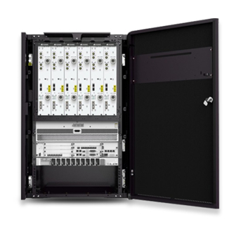
2.1 Exterior of the BTS3900C Cabinet This section describes the exterior of the BTS3900C cabinet. The BTS3900C cabinet is white and consists of an OMB (Ver.C) cabinet (shortened to OMB in this document) and a remote radio unit (RRU) subrack, as shown in Figure 2-1. - Page 14 BTS3900C (Ver.C) Hardware Description 2 BTS3900C Cabinet Figure 2-2 Interior of the BTS3900C AC cabinet Table 2-1 Components in the BTS3900C AC cabinet Component Optional/ Maximum Description Mandatory Quantity in a Single Cabinet Mandatory The electronic label unit (ELU) automatically reports the cabinet type.
- Page 15 220 V AC power into -48 V DC power. BBU3900 Mandatory The BBU3900 is a baseband processing unit. It processes the baseband signals of the base station. Issue 03 (2013-05-27) Huawei Proprietary and Confidential Copyright © Huawei Technologies Co., Ltd.
- Page 16 RF signals between the BBU and antenna system. AC surge Mandatory The AC surge protection box protection box provides surge protection for the input AC power. Issue 03 (2013-05-27) Huawei Proprietary and Confidential Copyright © Huawei Technologies Co., Ltd.
- Page 17 AC power into DC power. Interior of the BTS3900C DC Cabinet Figure 2-3 shows the interior of the BTS3900C DC cabinet, and Table 2-2 describes the components in the BTS3900C DC cabinet. Figure 2-3 Interior of the BTS3900C DC cabinet...
- Page 18 Two fan assemblies are separately installed at the left bottom and the left top in the OMB. Issue 03 (2013-05-27) Huawei Proprietary and Confidential Copyright © Huawei Technologies Co., Ltd.
-
Page 19: Bts3900C Engineering Specifications
Input Power Specifications The BTS3900C supports 110 V AC, 220 V AC, and -48 V DC power supply. When AC power is used, the base station converts AC power into -48 V DC power. -
Page 20: Equipment Specifications
BTS3900C DC: ≤ 25 kg (without the BBU and RRU) RRU subrack: ≤ 4 kg (without the RRU) NOTE For details about other engineering specifications of the BTS3900C, see 3900 Series Base Station Technical Description. Issue 03 (2013-05-27) Huawei Proprietary and Confidential... -
Page 21: Bts3900C Modules
3 BTS3900C Modules BTS3900C Modules About This Chapter This chapter describes the modules in the BTS3900C, including the BBU, RRU, and GPS surge protector. 3.1 BBU3900 Components This section describes the boards and modules of the BBU3900 in terms of their configuration rules, functions, ports, indicators, and DIP switches. -
Page 22: Bbu3900 Components
If there is no label on the FAN unit of the BBU, the ESN is printed on a mounting ear of the BBU, as shown in Figure 3-3. Issue 03 (2013-05-27) Huawei Proprietary and Confidential Copyright © Huawei Technologies Co., Ltd. -
Page 23: Bbu3900 Functions
GSM+LTE (shortened to GL), and BBU3900 UMTS+LTE (shortened to UL). Slots in the BBU3900 Slots in the BBU3900 are the same in different scenarios, as shown in Figure 3-4. Issue 03 (2013-05-27) Huawei Proprietary and Confidential Copyright © Huawei Technologies Co., Ltd. - Page 24 1 (with slots 0 and 1 occupied). UTRP Optional Slot 0 or 4 It is preferentially configured in slot 4. UEIU Optional Slot 18 UBRI Optional Slot 2 Issue 03 (2013-05-27) Huawei Proprietary and Confidential Copyright © Huawei Technologies Co., Ltd.
- Page 25 Mandatory Number WMPT/UMPT Mandatory Slot 6 or 7 A single UMPT or WMPT is preferentially configured in slot 7. The UMPT and WMPT cannot be configured simultaneously. Issue 03 (2013-05-27) Huawei Proprietary and Confidential Copyright © Huawei Technologies Co., Ltd.
- Page 26 The WBBPf takes precedence over the WBBPd in slot assignment. l If five or more WBBPs are required, ensure that a WBBP is installed in each of slots Issue 03 (2013-05-27) Huawei Proprietary and Confidential Copyright © Huawei Technologies Co., Ltd.
- Page 27 Slot 16 It must be configured in slot 16. UPEU Mandatory Slot 18 or 19 A single UPEU is preferentially configured in slot 19. UEIU Optional Slot 18 Issue 03 (2013-05-27) Huawei Proprietary and Confidential Copyright © Huawei Technologies Co., Ltd.
- Page 28 1 (with both slots 0 and 1 occupied). Figure 3-6 shows the typical configurations of the BBU3900 UMTS. Figure 3-6 Typical configuration of the BBU3900 UMTS Issue 03 (2013-05-27) Huawei Proprietary and Confidential Copyright © Huawei Technologies Co., Ltd.
- Page 29 Slot 18 or 19 A single UPEU is preferentially configured in slot 19. UEIU Optional Slot 18 UTRP Optional Slot 4 or 5 It is preferentially configured in slot 4. Issue 03 (2013-05-27) Huawei Proprietary and Confidential Copyright © Huawei Technologies Co., Ltd.
- Page 30 BBU3900 LTE. Figure 3-7 Typical configuration of the BBU3900 LTE BBU3900 GU Table 3-4 describes the slot assignment principles for the boards in the BBU3900 GU. Issue 03 (2013-05-27) Huawei Proprietary and Confidential Copyright © Huawei Technologies Co., Ltd.
- Page 31 The UMPT and WMPT cannot be configured simultaneously. GTMU Mandatory Slots 5 and 6 It is configured only in slot 6 (with slots 5 and 6 occupied). Issue 03 (2013-05-27) Huawei Proprietary and Confidential Copyright © Huawei Technologies Co., Ltd.
- Page 32 2 and 3. At least one of the WBBPs in slots 2 and 3 is WBBPd or WBBPf. The WBBPf takes precedence over the WBBPd during slot assignment. Issue 03 (2013-05-27) Huawei Proprietary and Confidential Copyright © Huawei Technologies Co., Ltd.
- Page 33 BBU3900 GU. Figure 3-8 Typical configuration of the BBU3900 GU BBU3900 GL Table 3-5 describes the slot assignment principles for the boards in the BBU3900 GL. Issue 03 (2013-05-27) Huawei Proprietary and Confidential Copyright © Huawei Technologies Co., Ltd.
- Page 34 Slot 0 or 4 It is preferentially configured in slot 4. The UTRP in GSM mode takes precedence over the UTRP in LTE mode during slot assignment. Issue 03 (2013-05-27) Huawei Proprietary and Confidential Copyright © Huawei Technologies Co., Ltd.
- Page 35 2. If more LBBPs are required, the LBBP is installed, in descending order of priority, in slot 2, 1, 0, 4, or 5. Issue 03 (2013-05-27) Huawei Proprietary and Confidential Copyright © Huawei Technologies Co., Ltd.
- Page 36 Slot 4 or 5 It is preferentially configured in slot 4. The UTRP in UMTS mode takes precedence over the UTRP in LTE mode during slot assignment. Issue 03 (2013-05-27) Huawei Proprietary and Confidential Copyright © Huawei Technologies Co., Ltd.
-
Page 37: Umpt
UMPTa1/ UMTS ATM over Four UMPTb1 E1/T1 or IP channels over E1/T1 Transmissio 10 Mbit/s, Full-duplex n over FE/ 100 Mbit/s, GE electrical or 1000 ports Mbit/s Issue 03 (2013-05-27) Huawei Proprietary and Confidential Copyright © Huawei Technologies Co., Ltd. - Page 38 3900 Series Base Station Technical Description. For the maximum number of DRBs and UEs in RRC_Connected mode, see section "Baseband Specifications" in 3900 Series Base Station Technical Description. Issue 03 (2013-05-27) Huawei Proprietary and Confidential Copyright © Huawei Technologies Co., Ltd.
- Page 39 In the lower left of the UMPTa1, UMPTb1, UMPTa2, and UMPTa6, there are silkscreens UMPTa1, UMPTb1, UMPTa2, and UMPTa6, respectively, indicating their board types. Functions The UMPT performs the following functions: Issue 03 (2013-05-27) Huawei Proprietary and Confidential Copyright © Huawei Technologies Co., Ltd.
- Page 40 (RF) signals received from the antenna to the satellite card. SFP female The port is used for BBU interconnection. connector The port is used to reset the board. Issue 03 (2013-05-27) Huawei Proprietary and Confidential Copyright © Huawei Technologies Co., Ltd.
- Page 41 An alarm is generated, and you need to locate the fault before deciding whether to replace the board. Green Steady on The board serves as an active board. Issue 03 (2013-05-27) Huawei Proprietary and Confidential Copyright © Huawei Technologies Co., Ltd.
- Page 42 FE/GE optical port, FE/GE electrical port, interconnection port, and E1/T1 port, which have no silkscreen on the boards, are near the corresponding port, as shown in Figure 3-15. Issue 03 (2013-05-27) Huawei Proprietary and Confidential Copyright © Huawei Technologies Co., Ltd.
- Page 43 Steady red An optical module fails to receive signals because of one of the following reasons: l The optical module is faulty. l The optical cable is broken. Issue 03 (2013-05-27) Huawei Proprietary and Confidential Copyright © Huawei Technologies Co., Ltd.
- Page 44 0.125s) but E1/T1 link 0 is not set up or an LOS alarm is generated. Steady red Alarms are generated on E1/T1 links 0 and Issue 03 (2013-05-27) Huawei Proprietary and Confidential Copyright © Huawei Technologies Co., Ltd.
- Page 45 0.125s) link 3. DIP Switch Two DIP switches on the UMPT are labeled SW1 and SW2. Figure 3-16 shows the positions of DIP switches on the UMPT. Issue 03 (2013-05-27) Huawei Proprietary and Confidential Copyright © Huawei Technologies Co., Ltd.
-
Page 46: Wmpt
Switch Balanced Unbalanced 3.1.6 WMPT The WCDMA main processing and transmission unit (WMPT) processes signals for the BBU3900 and manages resources for other boards in the BBU3900. Issue 03 (2013-05-27) Huawei Proprietary and Confidential Copyright © Huawei Technologies Co., Ltd. - Page 47 Provides USB ports. A USB flash drive that stores required software and configuration data can be inserted into the USB port to perform the automatic base station upgrade. Issue 03 (2013-05-27) Huawei Proprietary and Confidential Copyright © Huawei Technologies Co., Ltd.
- Page 48 Steady off l The board does not serve as an active board. l The board has not been activated. l The board is not providing any services. Issue 03 (2013-05-27) Huawei Proprietary and Confidential Copyright © Huawei Technologies Co., Ltd.
- Page 49 Steady off No connection is set Orange (ACT on the Blinking Data is being right side) transmitted or received. Steady off No data is being transmitted or received. Issue 03 (2013-05-27) Huawei Proprietary and Confidential Copyright © Huawei Technologies Co., Ltd.
- Page 50 SFP female connector FE optical port SMA connector Reserved RJ45 connector Commissioning USB connector USB commissioning port USB connector USB loading port Used for resetting the WMPT Issue 03 (2013-05-27) Huawei Proprietary and Confidential Copyright © Huawei Technologies Co., Ltd.
- Page 51 Table 3-19 Settings of the DIP switch SW1 on the WMPT DIP Status Description Switch The E1 resistance is set to 120 ohm. The E1 resistance is set to 75 ohm. Issue 03 (2013-05-27) Huawei Proprietary and Confidential Copyright © Huawei Technologies Co., Ltd.
-
Page 52: Wbbp
The WBBP in slot 2 or slot 3 could transfer the received CPRI data to other boards. Table 3-21 Specifications of the WBBP Board Number of Cells Number of UL CEs Number of DL Supported WBBPa WBBPb1 WBBPb2 WBBPb3 WBBPb4 WBBPd1 WBBPd2 WBBPd3 Issue 03 (2013-05-27) Huawei Proprietary and Confidential Copyright © Huawei Technologies Co., Ltd. - Page 53 Series Base Station Technical Description. Panel The WBBP has four types of panels, as shown in Figure 3-20, Figure 3-21, Figure 3-22, and Figure 3-23. Figure 3-20 Panel of the WBBPa Issue 03 (2013-05-27) Huawei Proprietary and Confidential Copyright © Huawei Technologies Co., Ltd.
- Page 54 When the WBBPd is installed in slot 2 or 3 and is connected to an RF module, the WBBPd supports the IC of uplink data. The WBBPf installed in slot 2 or slot 3 supports the baseband interconnection between BBUs. Issue 03 (2013-05-27) Huawei Proprietary and Confidential Copyright © Huawei Technologies Co., Ltd.
- Page 55 Pluggable (SFP) links, and the indicators are below the SFP ports. The WBBPd or WBBPf provides six indicators indicating the status of SFP links, and the indicators are above the SFP ports. Table 3-24 describes the indicators. Issue 03 (2013-05-27) Huawei Proprietary and Confidential Copyright © Huawei Technologies Co., Ltd.
- Page 56 (1) The security of the USB port is ensured by encryption. The TST port is used for commissioning the base station rather than importing or exporting the base station configuration. Issue 03 (2013-05-27) Huawei Proprietary and Confidential Copyright © Huawei Technologies Co., Ltd.
- Page 57 QSFP ports. Steady off The optical module cannot be detected. Ports Table 3-26 describes the three CPRI ports on the panel of the WBBPa and WBBPb. Issue 03 (2013-05-27) Huawei Proprietary and Confidential Copyright © Huawei Technologies Co., Ltd.
-
Page 58: Gtmu
BBU. It provides the reference clock, maintenance port, and external alarm collection port, monitors the power, controls and manages the entire BTS. Issue 03 (2013-05-27) Huawei Proprietary and Confidential Copyright © Huawei Technologies Co., Ltd. - Page 59 Maximum Carrier Mode Number GTMU/GTMUb IP over FE IP over E1 Panel Figure 3-24 Figure 3-25 show the panels of the GTMU and GTMUb. Figure 3-24 GTMU panel Issue 03 (2013-05-27) Huawei Proprietary and Confidential Copyright © Huawei Technologies Co., Ltd.
- Page 60 Software is being loaded to the for 0.125s board. Steady on An alarm is generated, and the board must be replaced. Steady off There is no fault. Issue 03 (2013-05-27) Huawei Proprietary and Confidential Copyright © Huawei Technologies Co., Ltd.
- Page 61 An optical module fails to receive or transmit signals because of the following reasons: l The optical module is faulty. l The fiber optic cable is broken. Issue 03 (2013-05-27) Huawei Proprietary and Confidential Copyright © Huawei Technologies Co., Ltd.
- Page 62 FE1 (on the Green (LINK Steady on The connection is set GTMUb) indicator on the left up successfully. side) Steady off No connection is set Issue 03 (2013-05-27) Huawei Proprietary and Confidential Copyright © Huawei Technologies Co., Ltd.
- Page 63 USB flash drive E1/T1 DB26 female Used for four E1/T1 inputs and outputs between connector the GTMU and the UELP or between BSCs Used for resetting the GTMU Issue 03 (2013-05-27) Huawei Proprietary and Confidential Copyright © Huawei Technologies Co., Ltd.
- Page 64 Switch The E1 resistance is set to 75 ohm. The E1 resistance is set to 120 ohm. The T1 resistance is set to 100 ohm. Others Unavailable Issue 03 (2013-05-27) Huawei Proprietary and Confidential Copyright © Huawei Technologies Co., Ltd.
- Page 65 Not supporting E1 bypass Others Unavailable Table 3-38 Description on S5 DIP Setting Description Switch Not supporting E1 bypass Supporting E1 bypass of level-1 cascaded base stations Issue 03 (2013-05-27) Huawei Proprietary and Confidential Copyright © Huawei Technologies Co., Ltd.
-
Page 66: Lmpt
Mbit/s Transmissio 10 Mbit/s, Full-duplex n over FE/ 100 Mbit/s, GE electrical and 1000 ports Mbit/s The following table lists the signaling specifications of the LMPT. Issue 03 (2013-05-27) Huawei Proprietary and Confidential Copyright © Huawei Technologies Co., Ltd. - Page 67 Enables configuration management, device management, performance monitoring, signaling processing, and radio source management Controls all boards in the system Provides the system clock Enables signal exchange between the eNodeB and MME/S-GW Issue 03 (2013-05-27) Huawei Proprietary and Confidential Copyright © Huawei Technologies Co., Ltd.
- Page 68 0.125s and off for houses this board are not 0.125s (eight activated. times) in the first l The S1 link is faulty. 2s and then off for Issue 03 (2013-05-27) Huawei Proprietary and Confidential Copyright © Huawei Technologies Co., Ltd.
- Page 69 Data is being transmitted or received. Steady off No data is being transmitted or received. Ports Table 3-44 describes the ports on the panel of the LMPT. Issue 03 (2013-05-27) Huawei Proprietary and Confidential Copyright © Huawei Technologies Co., Ltd.
-
Page 70: Lbbp
The LTE baseband processing unit (LBBP) in the BBU3900 processes baseband signals. Specifications The following table lists the signaling specifications of the LBBP. Table 3-45 Signaling specifications of the LBBP Board Signaling Specification (CAPS) LBBPc Issue 03 (2013-05-27) Huawei Proprietary and Confidential Copyright © Huawei Technologies Co., Ltd. - Page 71 Specifications" in 3900 Series Base Station Technical Description: the maximum number of data radio bearers, maximum RRC_connected users per cell, maximum RRC_connected users supported by an entire base station, and maximum uplink and downlink throughput per cell or user. Issue 03 (2013-05-27) Huawei Proprietary and Confidential Copyright © Huawei Technologies Co., Ltd.
- Page 72 MHz, 15 MHz, and 20 MHz 6x10M 1T2R 6x10M 2T2R The following table lists the number of cells, bandwidth, and antenna configurations supported by a single LBBP in LTE TDD scenarios. Issue 03 (2013-05-27) Huawei Proprietary and Confidential Copyright © Huawei Technologies Co., Ltd.
- Page 73 LBBPc boards to one LBBPd board, and only the CPRI ports on the LBBPd in slot 2 or 3 can connect to RF units. Panel The LBBP has two types of panels, as shown in Figure 3-27 Figure 3-28. Figure 3-27 LBBPc panel Issue 03 (2013-05-27) Huawei Proprietary and Confidential Copyright © Huawei Technologies Co., Ltd.
- Page 74 An alarm is generated, and you need to locate the fault before deciding whether to replace the board. Green Steady on The board serves as an active board. Issue 03 (2013-05-27) Huawei Proprietary and Confidential Copyright © Huawei Technologies Co., Ltd.
- Page 75 There is no mutual lock between dual- mode clock sources. l The data rates of the CPRI ports do not match each other. Issue 03 (2013-05-27) Huawei Proprietary and Confidential Copyright © Huawei Technologies Co., Ltd.
- Page 76 QSFP ports do not match each other. Steady off The optical module cannot be detected. Ports Table 3-53 describes the six CPRI ports on the LBBP panel. Issue 03 (2013-05-27) Huawei Proprietary and Confidential Copyright © Huawei Technologies Co., Ltd.
-
Page 77: Fan
It reports the status of the fans and fan unit, and dissipates heat from the BBU. Panel The FAN units fall into two types: FAN and FANc, as shown in Figure 3-29 Figure 3-30. Figure 3-29 FAN Issue 03 (2013-05-27) Huawei Proprietary and Confidential Copyright © Huawei Technologies Co., Ltd. - Page 78 Blinking green (on The module is for 1s and off for 1s) working. Blinking red (on for The module is 1s and off for 1s) reporting alarms. Issue 03 (2013-05-27) Huawei Proprietary and Confidential Copyright © Huawei Technologies Co., Ltd.
-
Page 79: Upeu
UPEUa, UPEUb, UPEUc, and UPEUd, respectively. Figure 3-31 UPEUa panel (1) BBU power switch (2) 7W2 connector Figure 3-32 UPEUb panel (1) BBU power switch (2) 7W2 connector Issue 03 (2013-05-27) Huawei Proprietary and Confidential Copyright © Huawei Technologies Co., Ltd. - Page 80 Provides two ports with each receiving one RS485 signal and another two ports with each receiving four Boolean signals. The Boolean signals can only be dry contact or Open Collector (OC) signals. Table 3-56 describes the specifications. Issue 03 (2013-05-27) Huawei Proprietary and Confidential Copyright © Huawei Technologies Co., Ltd.
-
Page 81: Backup Mode
The UPEU provides two RS485 signal ports, each receiving one RS485 signal, and two Boolean signal ports, each receiving four Boolean signals. Figure 3-35 shows the slots in the BBU. Figure 3-35 Slots in the BBU Issue 03 (2013-05-27) Huawei Proprietary and Confidential Copyright © Huawei Technologies Co., Ltd. -
Page 82: Ueiu
The universal environment interface unit (UEIU) of the BBU3900 transmits monitoring signals and alarm signals from external devices to the main control board. Panel Figure 3-36 shows the panel of the UEIU. Issue 03 (2013-05-27) Huawei Proprietary and Confidential Copyright © Huawei Technologies Co., Ltd. -
Page 83: Utrp
Port for RS485 input 1 connector 3.1.14 UTRP The universal transmission processing unit (UTRP) is an extended transmission board in the BBU3900 and provides ports connecting to transmission equipment. Issue 03 (2013-05-27) Huawei Proprietary and Confidential Copyright © Huawei Technologies Co., Ltd. - Page 84 1000 Mbit/ ports Transmiss 100 Mbit/s Full- ion over and 1000 duplex FE/GE Mbit/s optical ports Panel Figure 3-37 shows the panel of the UTRP2. Issue 03 (2013-05-27) Huawei Proprietary and Confidential Copyright © Huawei Technologies Co., Ltd.
- Page 85 Figure 3-40 Panel of the UTRP6 (with one STM-1 channel) Figure 3-41 shows the panel of the UTRP9. Figure 3-41 Panel of the UTRP9 (with four electrical ports) Issue 03 (2013-05-27) Huawei Proprietary and Confidential Copyright © Huawei Technologies Co., Ltd.
- Page 86 On for 1s and off for The board is running properly. On for 0.125s and off l The board is for 0.125s being loaded or configured. l The board is not started. Issue 03 (2013-05-27) Huawei Proprietary and Confidential Copyright © Huawei Technologies Co., Ltd.
- Page 87 Steady on l Before the configuration takes effect, none or both of the two E1 ports in GSM mode are functional. l The configuration has taken effect. Issue 03 (2013-05-27) Huawei Proprietary and Confidential Copyright © Huawei Technologies Co., Ltd.
- Page 88 GSM mode. Steady red Reserved Red or green Steady off The board is not working in UMTS mode. Steady green The board is working in UMTS mode. Issue 03 (2013-05-27) Huawei Proprietary and Confidential Copyright © Huawei Technologies Co., Ltd.
- Page 89 Table 3-67 Ports on the panel of the UTRP6 (with one STM-1 channel) Silkscreen Port Type Quantity Connector STM-1/OC-3 STM-1/OC-3 SFP female connector Table 3-68 lists the ports on the UTRP9. Issue 03 (2013-05-27) Huawei Proprietary and Confidential Copyright © Huawei Technologies Co., Ltd.
- Page 90 DIP switches on the UTRP3 and UTRP4. Figure 3-44 shows the DIP switches on the UTRPb4. Figure 3-43 DIP switches on the UTRP3 and UTRP4 Issue 03 (2013-05-27) Huawei Proprietary and Confidential Copyright © Huawei Technologies Co., Ltd.
- Page 91 Unavailable CAUTION SW1 and SW2 are set to OFF by default. SW1 corresponds to No.4 to No.7 E1 channels. SW2 corresponds to No.0 to No.3 E1 channels. Issue 03 (2013-05-27) Huawei Proprietary and Confidential Copyright © Huawei Technologies Co., Ltd.
-
Page 92: Uscu
Board Supported Mode Supported Satellite Card USCUb11 USCUb12 RT single-satellite card UMTS USCUb14 UBLOX single-satellite card UMTS USCUb22 Naviors dual-satellite card UMTS USCUb21 K161 dual-satellite card UMTS Issue 03 (2013-05-27) Huawei Proprietary and Confidential Copyright © Huawei Technologies Co., Ltd. - Page 93 The USCUb21 does not support RGPS signals. It uses a K161 satellite card, which must be purchased locally and installed onsite. Issue 03 (2013-05-27) Huawei Proprietary and Confidential Copyright © Huawei Technologies Co., Ltd.
- Page 94 The board does Steady off not serve as an active board. l The board has not been activated. l The board is not providing any services. Issue 03 (2013-05-27) Huawei Proprietary and Confidential Copyright © Huawei Technologies Co., Ltd.
-
Page 95: Ubri
The universal baseband radio interface board (UBRI) provides extended CPRI optical or electrical ports to implement convergence, distribution, and multi-mode transmission on the CPRI. Panel Figure 3-47 shows the panel of the UBRI. Issue 03 (2013-05-27) Huawei Proprietary and Confidential Copyright © Huawei Technologies Co., Ltd. - Page 96 Steady off l The board does not serve as an active board. l The board has not been activated. l The board is not providing any services. Issue 03 (2013-05-27) Huawei Proprietary and Confidential Copyright © Huawei Technologies Co., Ltd.
- Page 97 Description CPRI0 to CPRI5 SFP female Connecting the BBU connector and the RF module The following table lists the specifications of the CPRI ports on the UBRI. Issue 03 (2013-05-27) Huawei Proprietary and Confidential Copyright © Huawei Technologies Co., Ltd.
-
Page 98: Uelp
The UELP has one DIP switch, which is used to determine whether the receiving end is grounded. The DIP switch has four DIP bits. Figure 3-49 shows the DIP switch on the UELP. Issue 03 (2013-05-27) Huawei Proprietary and Confidential Copyright © Huawei Technologies Co., Ltd. -
Page 99: Uflp
Each universal FE lightning protection unit type B (UFLPB) provides protection for two channels of FE/GE signals. NOTE The UFLPB applies only to the LTE mode. Issue 03 (2013-05-27) Huawei Proprietary and Confidential Copyright © Huawei Technologies Co., Ltd. - Page 100 Table 3-84 UFLPB ports Port Location Silkscreen on the Connector Description Panel INSIDE side FE/GE0 and FE/GE1 RJ45 connector Connecting to a transmission board of the base station Issue 03 (2013-05-27) Huawei Proprietary and Confidential Copyright © Huawei Technologies Co., Ltd.
-
Page 101: Rru
TX/RX port A. The built-in BT also supplies power to the tower mounted amplifier (TMA). Table 3-85 lists the types of RRUs supported by the BTS3900C. For details about these RRUs, see the hardware description of the corresponding RRU. Table 3-85 Types of RRUs supported by the BTS3900C... - Page 102 GPS surge protector. Table 3-86 Ports on the GPS surge protector Silkscreen Connector Surge N-type female connector Ground terminal Protect N-type male connector Issue 03 (2013-05-27) Huawei Proprietary and Confidential Copyright © Huawei Technologies Co., Ltd.
-
Page 103: Bts3900C Power System
BTS3900C Power System About This Chapter The BTS3900C supports 110 V AC, 220 V AC, and -48 V DC power supply. When AC power is used, the base station converts AC power into -48 V DC power. 4.1 Configurations of Upper-Level Circuit Breakers and Power Cables This section describes the recommended configurations of upper-level circuit breakers and power cables for the BTS3900C. -
Page 104: Configurations Of Upper-Level Circuit Breakers And Power Cables
4 mm (0.025 in. 4.2 Power Distribution for the BTS3900C This section describes power distribution schemes for BTS3900C cabinets when 110 V AC, 220 V AC, or -48 V DC power is supplied. Issue 03 (2013-05-27) Huawei Proprietary and Confidential... - Page 105 Figure 4-2 shows the power distribution scheme for a cabinet supplied with -48 V DC power. Table 4-4 lists the specifications of fuses in the base station. Issue 03 (2013-05-27) Huawei Proprietary and Confidential Copyright © Huawei Technologies Co., Ltd.
-
Page 106: Etp48100-A1
The embedded telecommunication power 48100-A1 (ETP48100-A1) system consists of the power monitoring unit 11A (PMU 11A), power supply unit (PSU), and ETP48100-A1 subrack. Figure 4-3 shows the ETP48100-A1 components. Issue 03 (2013-05-27) Huawei Proprietary and Confidential Copyright © Huawei Technologies Co., Ltd. -
Page 107: Etp48100-A1 Subrack
ETP48100-A1 subrack. Table 4-5 Ports on an ETP48100-A1 subrack Port Silkscreen Connector AC input terminal INPUT OT terminal Circuit breaker LOAD0/LOAD1 DC output terminal OUTPUT OT terminal Issue 03 (2013-05-27) Huawei Proprietary and Confidential Copyright © Huawei Technologies Co., Ltd. -
Page 108: Pmu 11A
Monitors power distribution and reports alarms. Ports Figure 4-6 shows the ports on the PMU 11A and Table 4-6 describes these ports. Figure 4-6 Ports on the PMU 11A Issue 03 (2013-05-27) Huawei Proprietary and Confidential Copyright © Huawei Technologies Co., Ltd. - Page 109 Steady off The PMU 11A is faulty or there is no DC power supply. Alarm indicator Steady on An alarm is generated. Steady off No alarms is generated. Issue 03 (2013-05-27) Huawei Proprietary and Confidential Copyright © Huawei Technologies Co., Ltd.
-
Page 110: Psu
5 to 8 are set to 0000 by default before delivery. t bits (5, 6, 7, and 4.3.4 PSU The power supply unit (PSU) converts 110 V or 220 V AC power into -48 V DC power. Issue 03 (2013-05-27) Huawei Proprietary and Confidential Copyright © Huawei Technologies Co., Ltd. - Page 111 Figure 4-9 Indicators on the front panel of the PSU (1) Power indicator (2) Protection indicator (3) Fault indicator Table 4-9 describes the indicators on the front panel of the PSU. Issue 03 (2013-05-27) Huawei Proprietary and Confidential Copyright © Huawei Technologies Co., Ltd.
-
Page 112: Pdu10D-01
4.4 PDU10D-01 The power distribution unit 10D-01 (PDU10D-01) distributes -48 V DC power to all components in the cabinet. Exterior Figure 4-10 shows a PDU10D-01. Figure 4-10 PDU10D-01 Issue 03 (2013-05-27) Huawei Proprietary and Confidential Copyright © Huawei Technologies Co., Ltd. - Page 113 Positive power input wiring sectional area of the terminal cable supported is 25 mm (0.039 in. for one input or 16 (0.025 in. ) for two inputs. Issue 03 (2013-05-27) Huawei Proprietary and Confidential Copyright © Huawei Technologies Co., Ltd.
- Page 114 Two 5 A spare fuses, each used for transferring power less than 150 W. l One 30 A spare fuse, used for the 30 A output power ports on the PDU10D-01. Issue 03 (2013-05-27) Huawei Proprietary and Confidential Copyright © Huawei Technologies Co., Ltd.
-
Page 115: Ac Surge Protection Box
AC surge protection box. Figure 4-14 Panel of the AC surge protection box (1) AC surge protection box (2) Alarm port (3) AC power supply ports Issue 03 (2013-05-27) Huawei Proprietary and Confidential Copyright © Huawei Technologies Co., Ltd. - Page 116 Port for alarm ALARM Bare wire Port for collecting reporting the AC input surge protection alarm AC power supply Cord end terminal AC power supply port port Issue 03 (2013-05-27) Huawei Proprietary and Confidential Copyright © Huawei Technologies Co., Ltd.
-
Page 117: Bts3900C Monitoring System
BTS3900C Monitoring System About This Chapter The BTS3900C monitoring system monitors all boards and components in a BTS3900C cabinet. If any board or component is faulty, an alarm is automatically reported. The RRU or UPEU and UEIU in the BBU collect monitoring signals from boards and components to monitor the surrounding environment of the BTS3900C. -
Page 118: Principles For Monitoring A Bts3900C Cabinet
MON port on the BBU through the RS485 serial bus. In this manner, the boards monitor the cabinet. Principles for Monitoring a BTS3900C Cabinet in the 110 V AC or 220 V AC Power Supply Scenario... -
Page 119: Monitoring Boards
4 to 7 MON0 RJ45 Port for connector RS485 input MON1 RJ45 Port for connector RS485 input 5.3 Monitoring Boards This section describes monitoring boards in a BTS3900C cabinet. Issue 03 (2013-05-27) Huawei Proprietary and Confidential Copyright © Huawei Technologies Co., Ltd. -
Page 120: Heub
Monitors the running status of fans and supports fan speed adjustment based on temperature or controlled by the BBU. Reports collected information to the BBU. Ports Table 5-2 describes the ports on the HEUB. Issue 03 (2013-05-27) Huawei Proprietary and Confidential Copyright © Huawei Technologies Co., Ltd. -
Page 121: Pmu 11A
The power monitoring unit 11A (PMU 11A) manages the power system, monitors power distribution, and reports alarms. Exterior Figure 5-5 shows a PMU 11A. Figure 5-5 PMU 11A Issue 03 (2013-05-27) Huawei Proprietary and Confidential Copyright © Huawei Technologies Co., Ltd. - Page 122 Connects to the BBU or lower-level devices and collects alarms from lower-level devices. COM_485 RJ45 connector Reserved Indicators Table 5-4 describes the indicators on the PMU 11A. Issue 03 (2013-05-27) Huawei Proprietary and Confidential Copyright © Huawei Technologies Co., Ltd.
- Page 123 Figure 5-7 shows the DIP switches on the PMU 11A. Figure 5-7 DIP switches on the PMU 11A Table 5-5 describes the settings of the DIP switches. Issue 03 (2013-05-27) Huawei Proprietary and Confidential Copyright © Huawei Technologies Co., Ltd.
- Page 124 The bit 1 indicates ON, and the bit 0 indicates OFF. Bits significan use. 5 to 8 are set to 0000 by default before delivery. t bits (5, 6, 7, and Issue 03 (2013-05-27) Huawei Proprietary and Confidential Copyright © Huawei Technologies Co., Ltd.
-
Page 125: Bts3900C Components
The electronic label unit (ELU) reports the cabinet type automatically to facilitate troubleshooting. 6.3 BTS3900C Sensors The BTS3900C sensors consist of the door status sensor and temperature sensor. Issue 03 (2013-05-27) Huawei Proprietary and Confidential Copyright © Huawei Technologies Co., Ltd. -
Page 126: Fan Assembly
The fan assembly dissipates heat from the BTS3900C cabinet. A BTS3900C cabinet has two fan assemblies. The one at the left bottom in the OMB is the outer air circulation fan assembly and the one at the left top in the OMB is the inner air circulation fan assembly. -
Page 127: Bts3900C Sensors
6 BTS3900C Components Figure 6-2 ELU 6.3 BTS3900C Sensors The BTS3900C sensors consist of the door status sensor and temperature sensor. 6.3.1 Door Status Sensor The door status sensor, on the cabinet door, monitors whether the cabinet door is open. -
Page 128: Temperature Sensor
Table 6-1 Specifications of a temperature sensor Parameter Specifications Permissible voltage range 3.0 V DC to 5.5 V DC Temperature measurement range -55°C to +125°C (-67°F to +257°F) Temperature measurement error ±0.5°C (±32.9°F) Issue 03 (2013-05-27) Huawei Proprietary and Confidential Copyright © Huawei Technologies Co., Ltd. -
Page 129: Bts3900C Cables
RF cables. 7.2 Cable Outlets in a BTS3900C Cabinet All cables for a BTS3900C cabinet are routed into and out of the cabinet through the cable outlets at the bottom of the cabinet. 7.3 BTS3900C Cable Connections This chapter describes the cable connections in the BTS3900C. - Page 130 RRU and the RCU because it is not long enough. In this case, an AISG extension cable is used to extend the AISG multi-core cable for transmitting RS485 signals. Issue 03 (2013-05-27) Huawei Proprietary and Confidential Copyright © Huawei Technologies Co., Ltd.
-
Page 131: List Of Bts3900C Cables
BTS3900C (Ver.C) Hardware Description 7 BTS3900C Cables 7.1 List of BTS3900C Cables The BTS3900C cables are the PGND cables, power cables, transmission cables, CPRI cables, signal cables, and RF cables. PGND Cables PGND cables need to be installed onsite. Table 7-1 lists the cable connections. - Page 132 The Other End Connector Installation Connector Installation Position Position 7.5.6 HEUB EPC4 or LOAD9 on the 3V3 connector DC INPUT on Power Cable EPC6 PDU10D-01 the HEUB connector Issue 03 (2013-05-27) Huawei Proprietary and Confidential Copyright © Huawei Technologies Co., Ltd.
- Page 133 GTMU INSIDE part on Transfer Cable or WMPT in the UFLP in the the BBU l FE0 or FE1 port on the LMPT in the Issue 03 (2013-05-27) Huawei Proprietary and Confidential Copyright © Huawei Technologies Co., Ltd.
- Page 134 Fiber Optic Cable connector the GTMU, connector WMPT, or l SC UTRP in the connector l LC l SFP0 or connector SFP1 port on the LMPT in the BBU Issue 03 (2013-05-27) Huawei Proprietary and Confidential Copyright © Huawei Technologies Co., Ltd.
- Page 135 HEUB on the PMU11A Signal Cable in the ETP48100-A1 7.8.6 ELU Signal RJ45 RJ45 port on the RJ45 connector ELU port on the Cable connector HEUB Issue 03 (2013-05-27) Huawei Proprietary and Confidential Copyright © Huawei Technologies Co., Ltd.
- Page 136 USCU in the connector the GPS surge protector 7.8.4 HEUB-BBU RJ45 COM_IN port RJ45 connector MON1 port on Monitoring connector on the HEUB the UPEU in the Signal Cable Issue 03 (2013-05-27) Huawei Proprietary and Confidential Copyright © Huawei Technologies Co., Ltd.
-
Page 137: Cable Outlets In A Bts3900C Cabinet
AISG multi- wire cable 7.2 Cable Outlets in a BTS3900C Cabinet All cables for a BTS3900C cabinet are routed into and out of the cabinet through the cable outlets at the bottom of the cabinet. Position of cable outlet modules... - Page 138 (9) Reserved (5) Cable hole for the transmission cable Cable holes on the right cable outlet module Figure 7-3 shows cable holes on the right cable outlet module. Issue 03 (2013-05-27) Huawei Proprietary and Confidential Copyright © Huawei Technologies Co., Ltd.
-
Page 139: Bts3900C Cable Connections
This chapter describes the cable connections in the BTS3900C. The cable connections vary according to the configurations of the cabinet. 7.3.1 Power Cable Connections This section describes the power cable connections for a BTS3900C AC cabinet and a BTS3900C DC cabinet. Power Cable Connections for a BTS3900C AC Cabinet Figure 7-4 shows the power cable connections for a BTS3900C AC cabinet. - Page 140 BTS3900C (Ver.C) Hardware Description 7 BTS3900C Cables Figure 7-4 Power cable connections for a BTS3900C AC cabinet Table 7-12 Power cables in a BTS3900C AC cabinet Cable No. Cable Description 7.5.6 HEUB Power Cable 7.5.5 BBU Power Cable 7.5.3 ETP48100-A1 Power Cable 7.5.4 PDU10D-01 Power Cable...
-
Page 141: Transmission Cable Connections
7.5.1 DC Input Power Cable 7.3.2 Transmission Cable Connections This chapter describes the transmission cable connections of the BTS3900C in different modes. Transmission Cable Connections in a Single-Mode Base Station In GSM only, UMTS only, or LTE only mode, use the E1/T1 cable, FE/GE cable, or optical cable to transmit data. - Page 142 7 BTS3900C Cables Configuration Principles The BTS3900C cannot provide enough space for an SLPU. Therefore, surge protection boards need to be installed in the BBU subrack. The surge protection board cannot be positioned in slot 4 in the BBU to avoid interfering with power cables in the BTS3900C cabinet.
- Page 143 LMPT or UMPT. Figure 7-6 Transmission cable connections in a single-mode base station T1: E1/T1 Surge Protection Transfer Cable T2: 7.6.1 E1/T1 Cable 7.6.7 FE/GE Fiber Optic Cable Issue 03 (2013-05-27) Huawei Proprietary and Confidential Copyright © Huawei Technologies Co., Ltd.
- Page 144 Configuration Principles The BTS3900C cannot provide enough space for an SLPU. Therefore, surge protection boards need to be installed in the BBU subrack. The surge protection board cannot be positioned in slot 4 in the BBU to avoid interfering with power cables in the BTS3900C cabinet.
- Page 145 FE/GE electrical port or optical port on the WMPT or UMPT. The WMPT or UMPT is interconnected to the GTMU through the backplane. Issue 03 (2013-05-27) Huawei Proprietary and Confidential Copyright © Huawei Technologies Co., Ltd.
- Page 146 Comm the optical ports on the WMPT or UMPT and the GTMU. The WMPT or UMPT is interconnected to the Trans GTMU using the electrical port. missio Issue 03 (2013-05-27) Huawei Proprietary and Confidential Copyright © Huawei Technologies Co., Ltd.
- Page 147 WMPT or UMPT and the LMPT or UMPT. The LMPT or UMPT is interconnected to the WMPT or UMPT using the electrical port. Issue 03 (2013-05-27) Huawei Proprietary and Confidential Copyright © Huawei Technologies Co., Ltd.
- Page 148 In GSM+UMTS, GSM+LTE, or UMTS+LTE mode, independent transmission can be used. This section describes transmission cable connections for each mode. Configuration Principles The BTS3900C cannot provide enough space for an SLPU. Therefore, surge protection boards need to be installed in the BBU subrack. Issue 03 (2013-05-27) Huawei Proprietary and Confidential Copyright ©...
- Page 149 7 BTS3900C Cables The surge protection board cannot be positioned in slot 4 in the BBU to avoid interfering with power cables in the BTS3900C cabinet. The number of surge protection boards (UELP/UFLP/UFLPB) is based on the number of E1/FE/GE ports that need surge protection in the BBU. The surge protection board is installed, in descending order of priority, in slot 5, 1, or 0.
-
Page 150: Monitoring Signal Cable Connections
Transfer Cable 7.6.3 FE/GE Ethernet Cable 7.3.3 Monitoring Signal Cable Connections This section describes the monitoring signal cable connections for a BTS3900C AC cabinet and a BTS3900C DC cabinet. Issue 03 (2013-05-27) Huawei Proprietary and Confidential Copyright © Huawei Technologies Co., Ltd. - Page 151 Hardware Description 7 BTS3900C Cables Monitoring Signal Cable Connections for a BTS3900C AC Cabinet Figure 7-9 shows the monitoring signal cable connections for a BTS3900C AC cabinet. Table 7-17 describes the monitoring signal cables in a BTS3900C AC cabinet. Figure 7-9 Monitoring signal cable connections for a BTS3900C AC cabinet Table 7-17 Monitoring signal cables in a BTS3900C AC cabinet Cable No.
-
Page 152: Cpri Cable Connections
Monitoring signal cable for the door status sensor HEUB-BBU monitoring signal cable Temperature monitoring signal cable 7.3.4 CPRI Cable Connections CPRI cable connections in the BTS3900C cabinet depend on the mode of the BTS3900C. Issue 03 (2013-05-27) Huawei Proprietary and Confidential Copyright © Huawei Technologies Co., Ltd. - Page 153 Figure 7-12 CPRI cable connections in the UMTS only base station CPRI Cable Connections in the LTE Only Base Station Figure 7-13 shows CPRI cable connections in the LTE only base station. Issue 03 (2013-05-27) Huawei Proprietary and Confidential Copyright © Huawei Technologies Co., Ltd.
- Page 154 CPRI Cable Connections in the GSM+LTE Base Station Figure 7-15 shows CPRI cable connections in the GSM+LTE base station. Figure 7-15 CPRI cable connections in the GSM+LTE base station Issue 03 (2013-05-27) Huawei Proprietary and Confidential Copyright © Huawei Technologies Co., Ltd.
-
Page 155: Pgnd Cables
The maximum length of a PGND cable is 15 m (49.21 ft.). Exterior Figure 7-17 shows a PGND cable. Figure 7-17 PGND cable (1) OT terminal Cable Description Table 7-19 describes a PGND cable. Issue 03 (2013-05-27) Huawei Proprietary and Confidential Copyright © Huawei Technologies Co., Ltd. -
Page 156: Power Cables
(1) OT terminal NOTE l A DC input power cable for the BTS3900C has two wires with the cross-sectional area of 16 mm (0.025 in. l Colors and structures of cables vary in different region. If cables are purchased at local markets, they must comply with local rules and regulations. -
Page 157: Ac Input Power Cable
RTN(+) Black 7.5.2 AC Input Power Cable An AC input power cable for the BTS3900C feeds AC power into a BTS3900C AC cabinet. The maximum length of an AC input power cable is 6 m (19.68 ft.). Exterior Figure 7-19 shows an AC input power cable for the BTS3900C. -
Page 158: Etp48100-A1 Power Cable
BTS3900C (Ver.C) Hardware Description 7 BTS3900C Cables Table 7-21 AC input power cable for the BTS3900C Cable Wire Color Size of the OT Terminal and Cross-Sectional Area of the Cable 220 V AC single- L wire Brown M4, 4 mm (0.0062... -
Page 159: Bbu Power Cable
(2) EPC4 or EPC6 connector Cable Description A BBU power cable consists of two wires. Table 7-23 describes the pin assignment for the wires of a BBU power cable. Issue 03 (2013-05-27) Huawei Proprietary and Confidential Copyright © Huawei Technologies Co., Ltd. -
Page 160: Heub Power Cable
Regions Other Regions X1.A1 X2.2 Blue Gray X1.A3 X2.1 Black Blue 7.5.7 RRU Power Cable The RRU power cable feeds -48 V DC power into an RRU. Issue 03 (2013-05-27) Huawei Proprietary and Confidential Copyright © Huawei Technologies Co., Ltd. -
Page 161: Bts3900C Transmission Cables
Black Brown 7.6 BTS3900C Transmission Cables This chapter describes all the transmission cables used in a BTS3900C, including the exteriors, functions, and pin assignments of the transmission cables. 7.6.1 E1/T1 Cable An E1/T1 cable transmits baseband signals from BBU to the external transmission equipment. - Page 162 Table 7-27 Pin assignment for the wires of the 75-ohm E1 coaxial cable Pin on the DB26 Coaxial Unit No. Wire Label Type Male Connector X1.1 RX1+ X1.2 Ring RX1- X1.3 RX2+ X1.4 Ring RX2- Issue 03 (2013-05-27) Huawei Proprietary and Confidential Copyright © Huawei Technologies Co., Ltd.
- Page 163 White RX2- Green Twisted pair RX3+ White RX3- Brown Twisted pair RX4+ White RX4- X.19 Gray Twisted pair TX1+ X.20 White TX1- X.21 Blue Twisted pair TX2+ Issue 03 (2013-05-27) Huawei Proprietary and Confidential Copyright © Huawei Technologies Co., Ltd.
-
Page 164: E1/T1 Surge Protection Transfer Cable
This section describes the E1/T1 surge protection transfer cable connecting the UELP to the transmission board. This cable is optional. The length of an E1/T1 surge protection transfer cable is 0.65 m (2.13 ft). Issue 03 (2013-05-27) Huawei Proprietary and Confidential Copyright © Huawei Technologies Co., Ltd. - Page 165 Twisted pair cable X2.8 X1.5 X2.9 X1.24 Twisted pair cable X2.10 X1.23 X2.11 X1.8 Twisted pair cable X2.12 X1.7 X2.13 X1.1 Twisted pair cable X2.14 X1.2 X2.15 Issue 03 (2013-05-27) Huawei Proprietary and Confidential Copyright © Huawei Technologies Co., Ltd.
-
Page 166: Fe/Ge Ethernet Cable
Twisted pair X2.2 X1.1 White and X2.1 orange X1.6 Green Twisted pair X2.6 X1.3 White and X2.3 green X1.4 Blue Twisted pair X2.4 X1.5 White and blue X2.5 Issue 03 (2013-05-27) Huawei Proprietary and Confidential Copyright © Huawei Technologies Co., Ltd. -
Page 167: Fe Surge Protection Transfer Cable
Twisted pair X2.2 X1.1 White X2.1 X1.6 Green Twisted pair X2.6 X1.3 White X2.3 X1.4 Blue Twisted pair X2.4 X1.5 White X2.5 X1.8 Brown Twisted pair X2.8 Issue 03 (2013-05-27) Huawei Proprietary and Confidential Copyright © Huawei Technologies Co., Ltd. -
Page 168: Interconnection Cable Between The Fe Electrical Ports
The interconnection cable between the FE optical ports has an LC connector at each end, as shown in Figure 7-30. Figure 7-30 Interconnection cable between FE optical ports (1) LC connector Issue 03 (2013-05-27) Huawei Proprietary and Confidential Copyright © Huawei Technologies Co., Ltd. -
Page 169: Fe/Ge Fiber Optic Cable
The TX port on the BBU3900 must be connected to the RX port on the transmission equipment. The RX port on the BBU3900 must be connected to the TX port on the transmission equipment. Issue 03 (2013-05-27) Huawei Proprietary and Confidential Copyright © Huawei Technologies Co., Ltd. -
Page 170: Cpri Fiber Optic Cable
When a multimode fiber optic cable connects two RRUs, the breakout cable on both sides is 0.03 m (0.098 ft). Figure 7-35 shows the connection of the multimode fiber optic cable between a BBU and an RRU. Issue 03 (2013-05-27) Huawei Proprietary and Confidential Copyright © Huawei Technologies Co., Ltd. - Page 171 When a single-mode pigtail connects an RRU and an ODF, the breakout cables on the RRU side and ODF side are 0.03 m (0.098 ft) and 0.8 m (2.62 ft), respectively. Figure 7-37 shows the connection of the single-mode pigtail. Issue 03 (2013-05-27) Huawei Proprietary and Confidential Copyright © Huawei Technologies Co., Ltd.
- Page 172 (single-mode pigtail and trunk single-mode fiber optic cable) Pin Assignment Table 7-34 describes the labels on and recommended connections for the breakout cables of a CPRI fiber optic cable. Issue 03 (2013-05-27) Huawei Proprietary and Confidential Copyright © Huawei Technologies Co., Ltd.
-
Page 173: Bts3900C Signal Cables
CPRI RX port on RRU 0 7.8 BTS3900C Signal Cables This chapter describes all the signal cables used in a BTS3900C, including the exteriors, functions, and pin assignments of the signal cables. 7.8.1 Monitoring Signal Cable for the Fan Assembly The monitoring signal cable for the fan assembly is used for the HEUB to monitor the operating status of the fan assembly. -
Page 174: Temperature Monitoring Signal Cable
The PMU 11A monitoring signal cable is used to connect PMU 11A and HEUB. The cable transmits the monitoring information of the PMU 11A to the BBU. Exterior Figure 7-40 shows a PMU 11A monitoring signal cable. Issue 03 (2013-05-27) Huawei Proprietary and Confidential Copyright © Huawei Technologies Co., Ltd. -
Page 175: Heub-Bbu Monitoring Signal Cable
7.8.4 HEUB-BBU Monitoring Signal Cable The HEUB-BBU monitoring signal cable transmits the monitoring information collected by the HEUB to the BBU. Exterior Figure 7-41 shows an HEUB-BBU monitoring signal cable. Issue 03 (2013-05-27) Huawei Proprietary and Confidential Copyright © Huawei Technologies Co., Ltd. -
Page 176: Bbu Alarm Cable
The BBU alarm cable has an RJ45 connector at each end, as shown in Figure 7-42. One RJ45 connector at one end, however, may be removed and an appropriate terminal may be added according to the field requirements. Issue 03 (2013-05-27) Huawei Proprietary and Confidential Copyright © Huawei Technologies Co., Ltd. - Page 177 X1.3 White and Twisted X2.3 Boolean input 1+ green pair X1.6 Green X2.6 Boolean input 1- (GND) X1.5 White and Twisted X2.5 Boolean input 2+ blue pair Issue 03 (2013-05-27) Huawei Proprietary and Confidential Copyright © Huawei Technologies Co., Ltd.
-
Page 178: Elu Signal Cable
White Twisted pair X1.2 X2.2 Orange X1.3 X2.3 White Twisted pair X1.6 X2.6 Green X1.5 X2.5 White Twisted pair X1.4 X2.4 Blue X1.7 X2.7 White Twisted pair Issue 03 (2013-05-27) Huawei Proprietary and Confidential Copyright © Huawei Technologies Co., Ltd. -
Page 179: Monitoring Signal Cable For The Door Status Sensor
The GPS clock signal cable has an SMA male connector at one end and an N-type female connector at the other end, as shown in Figure 7-46. Issue 03 (2013-05-27) Huawei Proprietary and Confidential Copyright © Huawei Technologies Co., Ltd. -
Page 180: Adapter Used For Local Maintenance
Table 7-40 Pin assignment for the wires of the adapter used for local maintenance Pin of the USB Wire Color Wire Type Pin of the Ethernet Connector Connector X1.9 Blue Twisted pair X2.1 X1.8 White X2.2 Issue 03 (2013-05-27) Huawei Proprietary and Confidential Copyright © Huawei Technologies Co., Ltd. -
Page 181: Rru Rf Jumper
(RCU) to transmit control signals from a base station to the RET antenna. When the RRU is connected to the RET antenna, an AISG multi-wire cable transmits RS485 signals. Issue 03 (2013-05-27) Huawei Proprietary and Confidential Copyright © Huawei Technologies Co., Ltd. - Page 182 RS485 B Twisted orange pair X1.5 X2.5 Orange RS485 A X1.4 X2.4 White and green X1.9 and X1.4 are interconnected. X2.1 and X2.6 are +12 V interconnected. Issue 03 (2013-05-27) Huawei Proprietary and Confidential Copyright © Huawei Technologies Co., Ltd.
-
Page 183: Rru Aisg Extension Cable
Standard AISG Male AISG Connector) Female Connector) X1.1 X2.1 White and blue Twisted pair +12 V Blue X1.7 X2.7 White and orange Twisted pair DC Return A Issue 03 (2013-05-27) Huawei Proprietary and Confidential Copyright © Huawei Technologies Co., Ltd. - Page 184 Female Connector) Orange X1.3 X2.3 White and green Twisted pair RS485 B X1.5 X2.5 Green RS485 A X1.6 X2.6 White and brown Twisted pair +24 V Brown Issue 03 (2013-05-27) Huawei Proprietary and Confidential Copyright © Huawei Technologies Co., Ltd.