
Related Manuals for Huawei RH8100 V3


Summary of Contents for Huawei RH8100 V3
-
Page 1: User Guide
RH8100 V3 Server V100R003 User Guide Issue Date 2019-12-19 HUAWEI TECHNOLOGIES CO., LTD. - Page 2 Notice The purchased products, services and features are stipulated by the contract made between Huawei and the customer. All or part of the products, services and features described in this document may not be within the purchase scope or the usage scope. Unless otherwise specified in the contract, all statements, information, and recommendations in this document are provided "AS IS"...
-
Page 3: About This Document
V3, and how to install, remove, power on, power off, and configure the RH8100 V3, and perform other common operations on the RH8100 V3. This document provides guidance for you to manage the RH8100 V3. Intended Audience This document is intended for: ●... -
Page 4: Change History
Updated 7.3 Changing an iBMC User Password. 2017-08-31 Updated 7.6 Configuring the BIOS. 2017-07-20 Updated 7.6 Configuring the BIOS. 2017-05-25 Updated 2.11 Technical Specifications. 2017-04-22 Updated 3.4.1 Connecting a Ground Cable. Issue 30 (2019-12-19) Copyright © Huawei Technologies Co., Ltd. - Page 5 2015-11-10 Updated 2.5 Physical Structure. RH8100 V3 Server 2015-05-20 Combined the Installation Guide and RH8100 V3 Server Troubleshooting to form the RH8100 V3 Server User Guide . 2015-01-08 Added a note for PXE configuration in 7.6 Configuring the BIOS. 2014-11-20 Added the description of the FM-B in 2.5.2 Front I/O...
-
Page 6: Table Of Contents
3.4.6 Connecting a Power Cable............................. 98 3.4.7 Laying Out Cables................................102 3.4.8 Verifying Cable Connections............................103 4 Removing the RH8100 V3....................104 5 Removing and Installing Parts of the RH8100 V3............107 Issue 30 (2019-12-19) Copyright © Huawei Technologies Co., Ltd. - Page 7 5.5.15 Removing a Hard Disk Backplane.......................... 176 5.5.16 Installing a Hard Disk Backplane..........................177 5.6 Replacing the FM-B and Its Internal Components....................179 5.6.1 Removing the Front I/O Module..........................179 5.6.2 Installing a Front I/O Module............................. 180 Issue 30 (2019-12-19) Copyright © Huawei Technologies Co., Ltd.
- Page 8 5.9.3 Removing an AC PSU..............................254 5.9.4 Installing an AC PSU..............................256 5.9.5 Removing a DC PSU............................... 258 5.9.6 Installing a DC PSU................................ 260 5.10 Replacing an HFC and Its Internal Components....................262 Issue 30 (2019-12-19) Copyright © Huawei Technologies Co., Ltd.
- Page 9 5.11.6 Installing a Non-Hot-Swappable PCIe Card......................295 5.11.7 Removing the Rear I/O Board..........................297 5.11.8 Installing the Rear I/O Board............................299 6 Powering On and Off the RH8100 V3................303 6.1 Powering On the RH8100 V3............................303 6.2 Powering Off the RH8100 V3............................304 7 Configuring the RH8100 V3....................307...
- Page 10 RH8100 V3 Server User Guide Contents 10.2 Obtaining Technical Support............................368 A Appendix..........................370 A.1 Glossary....................................370 A.2 Sensor List.....................................371 Issue 30 (2019-12-19) Copyright © Huawei Technologies Co., Ltd.
-
Page 11: Safety Instructions
Personal Safety To ensure personal safety, note the following points: ● Only personnel certified or authorized by Huawei are allowed to perform the hardware installation. ● In case of any problems that may cause injury to personnel or damage to devices, immediately stop operations and report the problems to a project supervisor and take protective measures. - Page 12 Fasten the strap buckle and ensure that the ESD wrist strap is in contact against your skin. Insert the ground terminal attached to the ESD wrist strap into the jack on the grounded cabinet or chassis. Issue 30 (2019-12-19) Copyright © Huawei Technologies Co., Ltd.
- Page 13 Use only genuine components that can be queried in the Intelligent Computing Compatibility Checker. ● Only maintenance engineers authorized by Huawei are allowed to expand capacity. Avoid physical damage caused by electrostatic discharge, collision, and scratches. ● Before expanding capacity, back up data and isolate the equipment from the network to prevent data loss, service interruption, and network loops.
-
Page 14: Transportation Precautions
Table 1-1 Limits for the maximum weight carried per person Organization Weight (kg/lb) European Committee for Standardization (CEN) 25/55.13 International Organization for Standardization (ISO) 25/55.13 National Institute for Occupational Safety and Health 23/50.72 (NIOSH) Issue 30 (2019-12-19) Copyright © Huawei Technologies Co., Ltd. - Page 15 1 Safety Instructions Organization Weight (kg/lb) Health and Safety Executive (HSE) 25/55.13 General Administration of Quality Supervision, ● Male: 15/33.01 Inspection and Quarantine of the People's Republic of ● Female: 10/22.05 China (AQSIQ) Issue 30 (2019-12-19) Copyright © Huawei Technologies Co., Ltd.
-
Page 16: About The Rh8100 V3
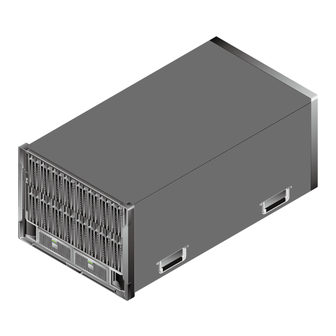
2.1 Functions This topic describes the RH8100 V3 functions. The Huawei RH8100 V3 server (marked as H88H-03 on the nameplate, RH8100 V3 for short) is a general-purpose 8-socket rack server developed for Internet, Internet data centers (IDCs), cloud computing, enterprise, and telecom service applications. -
Page 17: Appearance
RH8100 V3 Server User Guide 2 About the RH8100 V3 ● In single-system mode, the RH8100 V3 operates as a whole system and supports four or eight processors. ● In dual-system mode, the RH8100 V3 uses the Huawei FusionPar technology to implement the hard partitioning function. - Page 18 RH8100 V3 Server User Guide 2 About the RH8100 V3 Figure 2-1 RH8100 V3 (FM-A) Figure 2-2 shows the RH8100 V3 with the FM-B. Issue 30 (2019-12-19) Copyright © Huawei Technologies Co., Ltd.
- Page 19 RH8100 V3 Server User Guide 2 About the RH8100 V3 Figure 2-2 RH8100 V3 (FM-B) Figure 2-3 shows the RH8100 V3 with the FM-C. Issue 30 (2019-12-19) Copyright © Huawei Technologies Co., Ltd.
- Page 20 RH8100 V3 Server User Guide 2 About the RH8100 V3 Figure 2-3 RH8100 V3 (FM-C) Figure 2-4 shows the RH8100 V3 with the FM-D. Issue 30 (2019-12-19) Copyright © Huawei Technologies Co., Ltd.
-
Page 21: Front Panel
RH8100 V3 Server User Guide 2 About the RH8100 V3 Figure 2-4 RH8100 V3 (FM-D) Front Panel Figure 2-5, Figure 2-6, Figure 2-7, and Figure 2-8 show the RH8100 V3 front panel. Issue 30 (2019-12-19) Copyright © Huawei Technologies Co., Ltd. - Page 22 RH8100 V3 Server User Guide 2 About the RH8100 V3 Figure 2-5 RH8100 V3 front panel with the FM-A Compute modules 1 to 8 Memory board button/ from left to right status indicator Memory board ATTN Memory board backup indicator...
- Page 23 Press the yellow ejector release button on the HDD drawer. The ejector lever ejects automatically. Pull out the HDD drawer by holding the ejector lever. Table 2-2 describes the hard disk layout in the left HDD drawer on the RH8100 V3 with the FM-B. Issue 30 (2019-12-19)
- Page 24 HDD16 HDD19 HDD22 HDD14 HDD17 HDD20 HDD23 Figure 2-7 RH8100 V3 front panel with the FM-C Label (including the ESN Hard disk fault indicator label) Hard disk active indicator Hard disk Issue 30 (2019-12-19) Copyright © Huawei Technologies Co., Ltd.
- Page 25 RH8100 V3 Server User Guide 2 About the RH8100 V3 FM-C Table 2-4 describes the hard disk layout of the RH8100 V3 with the FM-C. Table 2-4 Hard disk layout of the RH8100 V3 with the FM-C HDD0 HDD2 HDD4...
-
Page 26: Rear Panel
RH8100 V3 Server User Guide 2 About the RH8100 V3 Table 2-5 Hard disk layout of the RH8100 V3 with the FM-D HDD0 HDD2 HDD4 HDD6 HDD1 HDD3 HDD5 HDD7 Figure 2-9 describes the mapping between memory board numbers and CPU socket numbers. - Page 27 RH8100 V3 Server User Guide 2 About the RH8100 V3 Figure 2-10 RH8100 V3 rear panel UID indicator Fan status indicator High-performance Fusion Power supply unit (PSU) Console-2 (HFC-2) status indicator Network interface card (NIC) PCIe card 10 (hot- swappable)
- Page 28 RH8100 V3 Server User Guide 2 About the RH8100 V3 Network port data NIC 1 transmission status indicator (The 82599 NIC (BC11FXEB) indicator is used as an example.) HFC-1 VGA port RJ45 serial port iBMC management network port USB port...
- Page 29 RH8100 V3 Server User Guide 2 About the RH8100 V3 Comp Bus/Device/ Slot Size Swap Function Modul Number (B/D/F) Comp C0/03/02 Full-height support 3/4-length modul Comp C0/02/00 Full-height support 3/4-length modul Comp A0/02/00 Full-height support 3/4-length modul Comp 40/02/00 Full-height...
- Page 30 To clear this alarm, install the PCIe card in an unrestricted PCIe slot. Note 2: If the back I/O module of the RH8100 V3 is fully configured (configured with seven FC adapters), SAN boot is not supported. Issue 30 (2019-12-19)
- Page 31 PCIe card with a PCI bridge is configured, the values of B/D/F may differ. ESNs An Equipment Serial Number (ESN) is a string that uniquely identifies a server. An ESN is required when you apply for technical support to Huawei. Figure 2-11 shows the ESN format by using the example 2102310QPD10F3001263.
-
Page 32: Ports
Indicates the vendor code (two characters). Indicates the year and month (two characters). Indicates the serial number (six digits). 2.3 Ports This topic describes the RH8100 V3 ports. Table 2-9, Table 2-10, and Table 2-11 describe the external ports on the front and rear panels of the RH8100 V3. - Page 33 RH8100 V3 Server User Guide 2 About the RH8100 V3 Name Type Single- Dual- Description ntity System System Mode Mode iBMC RJ45 Unavailab Unavailab In dual-system mode, the manag iBMC management network ement port of HFC-1 is unavailable networ and the network cable does k port not need to be connected.
-
Page 34: Indicators And Buttons
This topic describes the RH8100 V3 indicators and buttons. You can observe the indicators to determine RH8100 V3 status. Table 2-12 describes the indicators and buttons on the RH8100 V3 front panel. Issue 30 (2019-12-19) Copyright © Huawei Technologies Co., Ltd. - Page 35 RH8100 V3 Server User Guide 2 About the RH8100 V3 Table 2-12 Indicators and buttons on the front panel Meaning Color Single-System Mode Dual-System Mode Primary Yello ● Off: The server is not ● Off: System A is not power w and powered on.
- Page 36 RH8100 V3 Server User Guide 2 About the RH8100 V3 Meaning Color Single-System Mode Dual-System Mode Secondary Yello This indicator is ● Off: System B is not power w and unavailable and off, powered on. button/ green and this button is ●...
- Page 37 RH8100 V3 Server User Guide 2 About the RH8100 V3 Meaning Color Single-System Mode Dual-System Mode Secondary Blue This indicator is This button/indicator unavailable and off, helps identify and locate button/ and this button is system B in a cabinet.
- Page 38 RH8100 V3 Server User Guide 2 About the RH8100 V3 Meaning Color Single-System Mode Dual-System Mode Activity Green ● Off: The hard disk is ● Off: The hard disk is indicator not detected or is not detected or is for an faulty.
- Page 39 RH8100 V3 Server User Guide 2 About the RH8100 V3 Meaning Color Single-System Mode Dual-System Mode Fault Yello ● The activity indicator Hz and the fault indicator is blinking green at indicator is off: Data is for an 2 Hz and the fault...
- Page 40 RH8100 V3 Server User Guide 2 About the RH8100 V3 Meaning Color Single-System Mode Dual-System Mode 0–23 Hard disk Yello ● Off: The hard disk ● Off: The hard disk status w and cannot be detected cannot be detected indicators...
- Page 41 RH8100 V3 Server User Guide 2 About the RH8100 V3 Table 2-13 describes the indicators and buttons on the RH8100 V3 rear panel. Table 2-13 Indicators and buttons on the rear panel Meaning Color Single-System Mode Dual-System Mode Primary UID...
- Page 42 RH8100 V3 Server User Guide 2 About the RH8100 V3 Meaning Color Single-System Mode Dual-System Mode Connection Green ● Off: The port is not ● Off: The port is status in use. not in use. indicator for ● Steady green: The ●...
- Page 43 RH8100 V3 Server User Guide 2 About the RH8100 V3 Meaning Color Single-System Mode Dual-System Mode Fan status Red and ● Off: The server is ● Off: The server is indicator green not powered on. not powered on. ● Blinking red at 0.5 ●...
- Page 44 RH8100 V3 Server User Guide 2 About the RH8100 V3 Meaning Color Single-System Mode Dual-System Mode – Power Red and ● Steady green: The ● Steady green: The supply unit green PSU is operating PSU is operating (PSU) properly. properly.
- Page 45 PCIe card is operating properly. Figure 2-12 shows the indicators and button on an RH8100 V3 memory board and compute module. Table 2-14 describes the indicators and button. Issue 30 (2019-12-19) Copyright © Huawei Technologies Co., Ltd.
- Page 46 RH8100 V3 Server User Guide 2 About the RH8100 V3 Figure 2-12 Indicators and button on a memory board and compute module Memory board button/status Memory board ATTN indicator indicator Memory board backup Compute module status indicator indicator Issue 30 (2019-12-19)
- Page 47 ● Blinking red at 5 Hz: The compute module is not securely inserted. Figure 2-13 shows the indicator and button on the printed circuit board (PCB) of a memory board for the RH8100 V3. Table 2-15 describes the indicator and button.
-
Page 48: Physical Structure
DIMM turns on. You can easily locate the faulty DIMM for replacement or repair. 2.5 Physical Structure This topic describes the RH8100 V3 components. Figure 2-14 Figure 2-15 show the components of the RH8100 V3. - Page 49 RH8100 V3 Server User Guide 2 About the RH8100 V3 Figure 2-14 RH8100 V3 components (front view) Chassis DVD drive+LCD module Compute module Front I/O module (the FM-A is used as an example in the figure) Issue 30 (2019-12-19) Copyright © Huawei Technologies Co., Ltd.
- Page 50 RH8100 V3 Server User Guide 2 About the RH8100 V3 Figure 2-15 RH8100 V3 components (rear view) Fan module Power supply unit (PSU) High-performance Fusion Network interface card Console (HFC) (NIC) Trusted platform module USB flash drive (TPM) or trusted platform...
- Page 51 You can choose the configuration based on the requirement. For details about the front I/O module, see 2.5.2 Front I/O Module. Table 2-17 RH8100 V3 components (rear view) Name Description Dissipate heat from the server, support hot swap, and allow module one-fan failures.
- Page 52 0 on the other LOM, and port 1 on one LOM can communicate with only port 1 on the other LOM. If the RH8100 V3 operates in dual-system mode, one service system can obtain information from the other service system using the LOMs.
-
Page 53: Compute Module
PCIe cards. 2.5.1 Compute Module This topic describes the components of the RH8100 V3 compute module. Physical Structure The components of the RH8100 V3 compute module (CM for short) are shown in Figure 2-16. Figure 2-16 Compute module components... - Page 54 Provides three QPI channels for connecting to other CPUs. ® ® Each RH8100 V3 compute module supports one Intel Xeon E7-8800 v2, E7-8800 v3, or E7-8800 v4 CPU. NOTE ● When E7 v2/v3 CPUs are configured, use HFCs whose BOM number is 03022JBN.
- Page 55 RH8100 V3 Server User Guide 2 About the RH8100 V3 Figure 2-17 Installation positions of four compute modules Resource Use Restrictions In single-system mode, if four or eight CPUs are configured, the corresponding resource restrictions are listed in Table 2-19.
- Page 56 Mapping Between Logical CPU Sockets and Physical CPU Sockets Table 2-20 describes the mapping between logical CPU sockets and physical CPU sockets on the RH8100 V3 in single-system mode. Figure 2-18 shows the mapping between logical CPU sockets and physical CPU sockets.
- Page 57 Table 2-21 Table 2-22 describe the mapping between logical CPU sockets and physical CPU sockets on the RH8100 V3 in dual-system mode. Figure 2-19 shows the mapping between logical CPU sockets and physical CPU sockets. Table 2-21 Mapping between logical CPU sockets and physical CPU sockets in...
- Page 58 RH8100 V3 Server User Guide 2 About the RH8100 V3 Table 2-22 Mapping between logical CPU sockets and physical CPU sockets in system B N-core CPU System B Logical CPU Core Logical CPU Socket 0 to N-1 4N to 5N-1...
- Page 59 Figure 2-21 DIMM numbering rule in the alarm description Table 2-23 describes the mapping among the DIMM silk screens, DIMM numbers on iBMC, and DIMM numbers in alarm descriptions for the RH8100 V3 with 12- DDR3-DIMM memory boards. Issue 30 (2019-12-19)
- Page 60 : indicates the physical slot number of a memory board. Table 2-24 describes the mapping among the DIMM silk screens, DIMM numbers on iBMC, and DIMM numbers in alarm descriptions for the RH8100 V3 with 8- DDR3-DIMM memory boards. Table 2-24 Mapping among DIMM numbers...
- Page 61 : indicates the physical slot number of a memory board. Table 2-25 describes the mapping among the DIMM silk screens, DIMM numbers on iBMC, and DIMM numbers in alarm descriptions for the RH8100 V3 with 12- DDR4-DIMM memory boards. Table 2-25 Mapping among DIMM numbers...
- Page 62 : indicates the physical slot number of a memory board. Table 2-26 describes the mapping among the DIMM silk screens, DIMM numbers on iBMC, and DIMM numbers in alarm descriptions for the RH8100 V3 with 8- DDR4-DIMM memory boards. Table 2-26 Mapping among DIMM numbers...
-
Page 63: Front I/O Module
DIMM silk screens, DIMM numbers on iBMC, and DIMM numbers in alarm descriptions are consistent. 2.5.2 Front I/O Module This topic describes the hardware structure of the RH8100 V3 front I/O module. Issue 30 (2019-12-19) Copyright © Huawei Technologies Co., Ltd. - Page 64 RH8100 V3 Server User Guide 2 About the RH8100 V3 The RH8100 V3 provides three front I/O modules: ● The front I/O module of model A (FM-A) provides performance-balanced configuration. The FM-A supports a maximum of 12 SAS HDDs, SATA HDDs, or SSDs, two RAID controller cards, and six standard PCIe slots on PCIe riser cards.
- Page 65 RH8100 V3 Server User Guide 2 About the RH8100 V3 PCIe riser card RAID controller card 1 (RAID-1) RAID controller card 2 Supercapacitor (optional) (RAID-2) iBBU (or supercapacitor) PCIe card Table 2-27 describes the FM-A components. Table 2-27 FM-A component description...
- Page 66 RH8100 V3 Server User Guide 2 About the RH8100 V3 Item Description Supercap The supercapacitor provides power failure protection for a acitor RAID controller card with the LSISAS2208 chip. Intelligent An iBBU is required to provide power failure protection for a battery RAID controller card with the LSISAS2208 chip.
- Page 67 RH8100 V3 Server User Guide 2 About the RH8100 V3 Table 2-28 PCIe slots of the FM-A Port Bus/Device/ Slot Size pute Swap Function Number (B/D/F) Port 40/03/00 Full-height pute support half-length ule 4 Port 40/03/02 Full-height pute support half-length...
- Page 68 RH8100 V3 Server User Guide 2 About the RH8100 V3 Port Bus/Device/ Slot Size pute Swap Function Number (B/D/F) Port 80/02/00 pute support ule 5 Note 1: All slots support PCIe cards of 75 W or higher power, depending on the PCIe card model.
- Page 69 RH8100 V3 Server User Guide 2 About the RH8100 V3 Operating Restricted PCIe Slot Mode Note: The PCIe cards whose values of IO Ports are Yes in the Intelligent Computing Compatibility Checker require I/O resources and therefore cannot be installed in restricted PCIe slots. If such a PCIe card is installed in a restricted PCIe slot, the server reports a critical alarm indicating an I/O resource configuration error.
- Page 70 RH8100 V3 Server User Guide 2 About the RH8100 V3 Supercapacitor (optional) Table 2-30 describes the FM-B components. Table 2-30 FM-B component description Item Description FM-B The FM-B supports hard disks, RAID controller cards, and an iBBU or a supercapacitor.
- Page 71 RH8100 V3 Server User Guide 2 About the RH8100 V3 Figure 2-27 FM-C component structure Hard disk FM-C Hard disk backplane Supercapacitor (optional) Front I/O board of model C RAID-1 (FIO-C) RAID-2 Table 2-31 describes the FM-C components. Table 2-31 FM-C component description...
- Page 72 RH8100 V3 Server User Guide 2 About the RH8100 V3 Item Description Supercap The supercapacitor provides power failure protection for a acitor RAID controller card with the LSISAS3108 chip. FIO-C The FIO-C houses a RAID controller card and provides the management function.
- Page 73 RH8100 V3 Server User Guide 2 About the RH8100 V3 Hard disk FM-D Hard disk backplane Supercapacitor (optional) Front I/O board of model D RAID-1 (FIO-D) RAID-2 Table 2-32 describes the FM-D components. Table 2-32 FM-D component description Item Description...
-
Page 74: Logical Structure
FM-A, FM-B, FM-C, and FM-D. They respectively apply to RH8100 V3 with 12 SAS HDDs, SATA HDDs, or SSDs, 24 SAS HDDs, SATA HDDs, or SSDs, 8 SAS HDDs, SATA HDDs, or SSDs, and 8 SAS HDDs, SATA HDDs, SSDs, or NVMe PCIe SSDs. - Page 75 RH8100 V3 Server User Guide 2 About the RH8100 V3 – E7-8800 v3: The maximum QPI transmission rate is 9.6 GT/s, and the two-way transmission bandwidth of a single QPI port is 24 GB/s. – E7-8800 v4: The maximum QPI transmission rate is 9.6 GT/s, and the two-way transmission bandwidth of a single QPI port is 24 GB/s.
- Page 76 RH8100 V3 Server User Guide 2 About the RH8100 V3 Figure 2-30 Memory subsystem topology Figure 2-31 PCIe topology (FM-A) Issue 30 (2019-12-19) Copyright © Huawei Technologies Co., Ltd.
- Page 77 RH8100 V3 Server User Guide 2 About the RH8100 V3 Figure 2-32 PCIe topology (FM-B or FM-C) Figure 2-33 Topology of I/O ports (single-system mode) Issue 30 (2019-12-19) Copyright © Huawei Technologies Co., Ltd.
- Page 78 ● The dual-system mode is also called dual-partition mode. In this mode, the RH8100 V3 operates as two 4-socket systems: systems A and B, which are also called partitions A and B. The operating mode of the RH8100 V3 can be set based on service requirements to maximize return on investment (ROI).
-
Page 79: Ras Features
CPUs are divided into two groups and the four CPUs in each group are in a QPI topology. In short, the CPUs connected over QPI links are in one partition. ● The default mode is single-system. In this mode, the RH8100 V3 operates as a single system. ●... -
Page 80: Software And Hardware Compatibility
Easy switching: You can implement one-click switching of the LCD and DVD drive between the two partitions using the iBMC WebUI or LCD. The RH8100 V3 operates in single-system mode by default. You can switch the RH8100 V3 to the dual-system mode using the FusionPar technology. In dual-... - Page 81 ● Standard PCIe 2.0 x4 card ● Standard PCIe 2.0 x8 card ● Standard PCIe 2.0 x16 card (The RH8100 V3 supports a maximum of four standard PCIe 2.0 x16 cards.) ● Standard PCIe 3.0 x4 card ● Standard PCIe 3.0 x8 card ●...
-
Page 82: Product Specifications
60 MB L3 cache capacity and 24 cores. (Four processors can also be configured.) NOTE ● The RH8100 V3 supports memory board hot swap only when equipped with E7 v2 or E7 v3 processors. ● When E7 v2/v3 CPUs are configured, use HFCs whose BOM number is 03022JBN. - Page 83 SSDs, or NVMe PCIe SSDs. NVMe PCIe SSDs do not support the hardware RAID function. NOTE ● The RH8100 V3 cannot be equipped with Huawei ES3000 V3 NVMe PCIe SSDs and Intel NVMe PCIe SSDs at the same time. ● When Huawei ES3000 V3 NVMe PCIe SSDs are installed, upgrade the ES3000 V3 driver to the latest version.
- Page 84 – Three Huawei ES3000s and one GPU ● Two RAID controller card slots are on FM-A. NOTE ● The RH8100 V3 cannot be equipped with Huawei ES3000 V3 NVMe PCIe SSD cards and Intel NVMe PCIe SSDs at the same time.
-
Page 85: Technical Specifications
Power-on password and administrator password. Supported OSs For details, see Intelligent Computing Compatibility Checker. 2.11 Technical Specifications This topic describes the technical specifications for the RH8100 V3. Table 2-37 describes the technical specifications for the RH8100 V3. Table 2-37 Technical specifications Category Item... - Page 86 RH8100 V3 Server User Guide 2 About the RH8100 V3 Category Item Specifications Weight Maximum weight: ● 8-bay server: 152 kg (335.10 lb) ● 12-bay server: 160 kg (352.74 lb) ● 24-bay server: 165 kg (363.76 lb) Packaging material weight: 20 kg (44.10 lb)
- Page 87 RH8100 V3 Server User Guide 2 About the RH8100 V3 Category Item Specifications Acoustic noise The data listed in the following is the declared A-weighted sound power levels (LWAd) and declared average bystander position A- weighted sound pressure levels (LpAm) when the server is operating in a 23°C (73.4°F)
-
Page 88: Specifications
RH8100 V3 Server User Guide 2 About the RH8100 V3 Category Item Specifications Power supply Input voltage ● 2500 W DC PSU: –48 V DC to –60 V DC unit (PSU) NOTE input The following requirements must be met when this... - Page 89 Category Item Specifications Power PSU power The RH8100 V3 supports PSUs in 2+2 or 1+1 specifications rating redundancy mode. The following lists the power rating for each type of PSU: ● 2500 W DC PSU: 2500 W (input voltage: –...
-
Page 90: Installing The Rh8100 V3
This topic describes how to check the installation environment and provides installation rules. Checking the Installation Environment To ensure the proper installation and operating of the RH8100 V3, prepare the installation environment before installation. Check that the cabinet, space, temperature, and humidity all conform to the following requirements. -
Page 91: Unpacking The Chassis
Servers can be stacked in a cabinet. If the cabinet space is sufficient, the distance between two adjacent servers is 1 U high. ● The RH8100 V3 is heavy. Install it in the lower part of the cabinet to keep the cabinet in balance. 3.2 Unpacking the Chassis This topic describes how to unpack the server chassis. - Page 92 RH8100 V3 Server User Guide 3 Installing the RH8100 V3 The following tools are available: ● Protective gloves ● ESD gloves ● ESD wrist strap ● Box cutter Procedure Step 1 Check whether the package is in good condition. If the package is damaged (for example, the package is soaked or deformed, or the seals or Cargo Problem Feedback Form .
-
Page 93: Installing The Server
Install the RH8100 V3 if: ● Additional RH8100 V3s are required in a cabinet to expand capacity. ● The RH8100 V3 is faulty and needs to be replaced with a new one. Issue 30 (2019-12-19) Copyright © Huawei Technologies Co., Ltd. - Page 94 RH8100 V3 Server User Guide 3 Installing the RH8100 V3 ● A server of another model needs to be replaced with the RH8100 V3. Impact on the System This operation has no adverse impact on the system. Prerequisites Conditions ●...
- Page 95 RH8100 V3 Server User Guide 3 Installing the RH8100 V3 Figure 3-2 Installation position Step 2 Install floating nuts. Determine the position for installing a floating nut based on the installation plan. The floating nuts and screws are used together to tighten the screws.
- Page 96 RH8100 V3 Server User Guide 3 Installing the RH8100 V3 Fasten one end of a floating nut to the square hole in a mounting bar at the front of the cabinet. See step (1) in Figure 3-4. Figure 3-4 Installing a floating nut Fasten the upper end of the floating nut to the mounting bar at the front of the cabinet by using the floating nut hook.
- Page 97 Place the removed compute module onto an ESD platform. Step 5 Install the RH8100 V3. Lift the RH8100 V3 on both sides and move it to the cabinet (at least four persons are required to perform this operation). Place the RH8100 V3 onto the guide rails and push it into the cabinet. See...
- Page 98 3 Installing the RH8100 V3 Figure 3-7 Installing an RH8100 V3 When the two mounting ears on the RH8100 V3 come into contact with the mounting bars of the cabinet, tighten the captive screws on the mounting ears to secure the RH8100 V3. See step (2) in Figure 3-7.
-
Page 99: Connecting External Cables
3 Installing the RH8100 V3 Figure 3-8 Installing a compute module ----End 3.4 Connecting External Cables This topic describes how to connect external cables to the RH8100 V3. 3.4.1 Connecting a Ground Cable Scenarios ● When AC or high-voltage DC power supplies are used, the chassis is grounded over the protective earth (PE) conductor of each power cable, and the chassis ground terminal needs to be grounded as well. - Page 100 RH8100 V3 Server User Guide 3 Installing the RH8100 V3 ● The server and its internal components are properly installed. ● Ground cables are available and placed near the server. Data No data preparation is required for this operation. Tools ●...
-
Page 101: Connecting Cables To A Mouse, Keyboard, And Vga Port
RH8100 V3 Server User Guide 3 Installing the RH8100 V3 Figure 3-10 Connecting a ground cable Step 3 Use a Phillips screwdriver to loosen the screw on the ground point in the cabinet. (You are advised to choose the screw nearest to the server.) Connect the other end of the ground cable to the removed screw. - Page 102 RH8100 V3 Server User Guide 3 Installing the RH8100 V3 Prerequisites Conditions No special condition is required for this operation. Data Data preparation is not required for this operation. Procedure Step 1 Connect the USB connector on the PS/2 cable to the USB port on the front or rear panel of the server.
-
Page 103: Connecting A Network Cable
RH8100 V3 Server User Guide 3 Installing the RH8100 V3 ----End 3.4.3 Connecting a Network Cable Scenarios Connect a network cable if: ● The network needs to be set up over a gigabit Ethernet (GE). ● You want to log in to the intelligent baseboard management controller (iBMC) of the server over the management network port for device management. - Page 104 RH8100 V3 Server User Guide 3 Installing the RH8100 V3 Step 2 Number the new network cable. ● The new network cable must have the same number as the one to be replaced. ● Use the same type of label for network cables. Record the name and number of the local device to be connected on one side of the network cable, and those of the peer device on the other side.
-
Page 105: Connecting To A Usb Device
RH8100 V3 Server User Guide 3 Installing the RH8100 V3 Figure 3-12 Connecting a network cable Step 6 Connect the other end of the network cable to the peer network port. Connect the other cable connector to the peer device based on the network plan. - Page 106 Electrostatic discharge (ESD) wrist strap Hardware The USB storage device to be connected operates properly. Procedure Step 1 Connect the USB device to the USB port on the RH8100 V3. See Figure 3-13. Figure 3-13 Connecting to a USB device...
-
Page 107: Connecting A Serial Cable
RH8100 V3 Server User Guide 3 Installing the RH8100 V3 3.4.5 Connecting a Serial Cable Scenarios The rear panel of the server provides a standard DB9 serial port (three-pin serial port), which works as the system serial port by default. You can set it as the iBMC serial port using the iBMC CLI. -
Page 108: Connecting A Power Cable
● To ensure device and human safety, use the dedicated power cable. ● The power cable is used only for the RH8100 V3. Do not use the power cable for other devices. ● The RH8100 V3 supports 2000 W and 3000 W AC PSUs. - Page 109 16 A. The connector of the power distribution unit (PDU) must be the same as the connector on the PSU. ● If you use DC PSUs, a PGND cable is properly connected to the RH8100 V3. Data No data preparation is required for this operation.
- Page 110 RH8100 V3 Server User Guide 3 Installing the RH8100 V3 Figure 3-15 Connecting an AC power cable Close the securing latch on the PSU. See step (2) in Figure 3-15. Connect the other end of the AC power cable to the AC power socket on the cabinet.
- Page 111 RH8100 V3 Server User Guide 3 Installing the RH8100 V3 Figure 3-16 Removing a protection cover from a PSU Connect the OT terminal of the negative power cable to the NEG(-) wiring terminal of the DC PSU, and connect the OT terminal of the positive power cable to the RTN(+) wiring terminal of the PSU.
-
Page 112: Laying Out Cables
RH8100 V3 Server User Guide 3 Installing the RH8100 V3 3.4.7 Laying Out Cables Basic Rules ● Lay out and bind cables of different types of cables (such as power and signal cables) separately. Ensure that the distance between power cables and signal cables is longer than or equal to 30 mm (1.18 in.) when you lay out the... -
Page 113: Verifying Cable Connections
RH8100 V3 Server User Guide 3 Installing the RH8100 V3 NO TICE To ensure optimal heat dissipation, do not block the air exhaust vents of PSUs. 3.4.8 Verifying Cable Connections Before verifying cable connections, ensure that the power is off. Any incorrect or loose connection may cause personal injury or equipment damage. -
Page 114: Removing The Rh8100 V3
Prerequisites Conditions NO TICE At least four people are required to lift the RH8100 V3 because it is heavy. All services and programs running on the RH8100 V3 are stopped. Data Data on the RH8100 V3 has been backed up. - Page 115 Figure 4-1. Figure 4-1 Removing a compute module Place the removed compute module onto an ESD platform. Step 4 Remove the protection covers of the captive screws on the RH8100 V3 panel. See step (1) in Figure 4-2. Issue 30 (2019-12-19)
- Page 116 (2) in Figure 4-2. Step 6 Pull the RH8100 V3 out of the cabinet along the guide rails. See step (3) in Figure 4-2. Step 7 Place the removed RH8100 V3 onto an ESD platform. Then install a new chassis or relocate the removed RH8100 V3.
-
Page 117: Removing And Installing Parts Of The Rh8100 V3
Removing and Installing Parts of the RH8100 V3 About This Chapter This topic describes the replaceable parts of the RH8100 V3 and how to replace them. NO TICE ● Ensure that the obtained spare parts are compatible and function properly before any replacement. -
Page 118: Replaceable Parts
User Guide 5 Removing and Installing Parts of the RH8100 V3 5.1 Replaceable Parts This topic describes the replaceable parts of the RH8100 V3. The RH8100 V3 is 8 U high and has the following replaceable parts: ● Compute module ●... - Page 119 V3. Then you have removed all power cables from the server. Data ● You have obtained the cabinet number and chassis number of the RH8100 V3. ● You have located the RH8100 V3 based on the preceding information, and labeled its panel to prevent misoperations.
-
Page 120: Installing A Compute Module
The CPU on a compute module has failed. Prerequisites Conditions ● You have powered off the RH8100 V3. For details, see 6.2 Powering Off the RH8100 V3. Then you have removed all power cables from the server. Issue 30 (2019-12-19) - Page 121 You have installed a CPU on the compute module to be installed. For details, 5.2.6 Installing a CPU. Data ● You have obtained the cabinet number and chassis number of the RH8100 V3. ● You have located the RH8100 V3 based on the preceding information, and labeled its panel to prevent misoperations. ●...
-
Page 122: Removing A Memory Board
Prerequisites Conditions None Data ● You have obtained the cabinet number and chassis number of the RH8100 V3. ● You have located the RH8100 V3 based on the preceding information, and labeled its panel to prevent misoperations. ● You have determined the position on the RH8100 V3 for removing a memory board. - Page 123 User Guide 5 Removing and Installing Parts of the RH8100 V3 NO TICE ● When equipped with E7 v2 or E7 v3 processors, the RH8100 V3 supports the DIMM hot swap function. The prerequisite is that live memory migration is enabled.See...
- Page 124 RH8100 V3 Server User Guide 5 Removing and Installing Parts of the RH8100 V3 Figure 5-3 Hot swap of a memory board The system starts to migrate data, and the progress bar displays the migration progress. When the migration progress reaches 100%, the migration is complete and the faulty memory board powers off.
-
Page 125: Installing A Memory Board
RH8100 V3 Server User Guide 5 Removing and Installing Parts of the RH8100 V3 Step 4 Gently pull the memory board out of the slot while holding the ejector lever. See steps (2) and (3) in Figure 5-4. Figure 5-4 Removing a memory board Step 5 Remove all DIMMs from the memory board, and place the memory board in an ESD bag. - Page 126 You have installed all DIMMs on the memory board to be installed. For details, see 5.2.8 Installing a DIMM. Data ● You have obtained the cabinet number and chassis number of the RH8100 V3. ● You have located the RH8100 V3 based on the preceding information, and labeled its panel to prevent misoperations. ●...
-
Page 127: Removing A Cpu
Checker. Scenarios NO TICE ● Only the personnel authorized by Huawei and Huawei technical support can remove a CPU from a Huawei server. ● Do not wear ESD gloves during CPU replacement. The gloves may catch on pins on the CPU socket and damage it. - Page 128 You have powered off the RH8100 V3. For details, see 6.2 Powering Off the RH8100 V3. Then you have removed all power cables from the server. ● You have removed the compute module from the RH8100 V3. For details, see 5.2.1 Removing a Compute Module. Data ●...
- Page 129 RH8100 V3 Server User Guide 5 Removing and Installing Parts of the RH8100 V3 Step 3 Lift the heat sink out of the server. See step (2) in Figure 5-6. Step 4 NO TICE ● Do not use a tool or sharp object to lift the levers on the CPU socket.
-
Page 130: Installing A Cpu
Checker. Scenarios NO TICE ● Only the personnel authorized by Huawei and Huawei technical support personnel can install a CPU in Huawei servers. ● Do not wear ESD gloves during CPU replacement. The gloves may catch on pins on the CPU socket and damage it. - Page 131 RH8100 V3 Server User Guide 5 Removing and Installing Parts of the RH8100 V3 ● You have removed the compute module from the RH8100 V3. For details, see 5.2.1 Removing a Compute Module. Data ● You have obtained the cabinet number and chassis number of the RH8100 V3.
- Page 132 RH8100 V3 Server User Guide 5 Removing and Installing Parts of the RH8100 V3 Chip Size Quantity of Thermal Compound 40 mm x 40 mm 0.3 ml (1.57 in. x 1.57 in.) 30 mm x 30 mm 0.2 ml (1.18 in. x 1.18 in.)
- Page 133 RH8100 V3 Server User Guide 5 Removing and Installing Parts of the RH8100 V3 Figure 5-10 Smeared thermal compound layer Step 7 NO TICE ● To prevent damage to the CPU, CPU socket, or mainboard, ensure that the securing rod on the CPU socket is fully open before you install the CPU in the socket.
- Page 134 RH8100 V3 Server User Guide 5 Removing and Installing Parts of the RH8100 V3 Figure 5-11 Installing a CPU Figure 5-12 Incorrectly placed CPU Step 8 Close the load plate to secure the CPU. See step (2) in Figure 5-11.
-
Page 135: Removing A Dimm
● The DIMM has failed. ● The DIMM needs to be replaced with a new model. Prerequisites Conditions You have removed the memory board from the RH8100 V3. For details, see 5.2.3 Removing a Memory Board. Data ● You have obtained the cabinet number and chassis number of the RH8100 V3. -
Page 136: Installing A Dimm
The memory capacity needs to be expanded. The rules for installing DIMMs are as follows: ● If each memory board supports 12 DIMMs, the RH8100 V3 supports 192 DDR3 or DDR4 DIMMs. Each memory board provides four memory channels: Issue 30 (2019-12-19) - Page 137 RH8100 V3 Server User Guide 5 Removing and Installing Parts of the RH8100 V3 0, 1, 2, and 3. Figure 5-15 shows the internal structure of a memory board with 12 DIMMs, and Table 5-2 lists the memory channels. Figure 5-15 Internal structure of a memory board with 12 DIMMs...
- Page 138 J1, J4, J7, J10, J2, J5, J8, J11, J3, J6, J9, and J12 ● If each memory board supports eight DIMMs, the RH8100 V3 supports 128 DDR3 or DDR4 DIMMs. Each memory board provides four memory channels: 0, 1, 2, and 3.
- Page 139 Table 5-5 DIMM configuration rules DIMM Installation Sequence Each CPU J1, J4, J7, J10, J2, J5, J8, and J11 Prerequisites Conditions You have removed the memory board from the RH8100 V3. For details, see 5.2.3 Removing a Memory Board. Data ●...
-
Page 140: Replacing A Dvd Drive+Lcd Module And Its Internal Components
Prerequisites Conditions None Data ● You have obtained the cabinet number and chassis number of the RH8100 V3. ● You have located the RH8100 V3 based on the preceding information, and labeled its panel to prevent misoperations. Issue 30 (2019-12-19) -
Page 141: Installing A Dvd Drive+Lcd Module
RH8100 V3 Server User Guide 5 Removing and Installing Parts of the RH8100 V3 ● You have determined the position on the RH8100 V3 for removing a DVD drive+LCD module. Tools ● ESD gloves ● Packaging materials, for example, an ESD bag Procedure Step 1 Wear an ESD wrist strap or ESD gloves. - Page 142 No special conditions are required for this operation. Data ● You have obtained the cabinet number and chassis number of the RH8100 V3. ● You have located the RH8100 V3 based on the preceding information, and labeled its panel to prevent misoperations.
-
Page 143: Removing The Lcd
This topic describes how to remove the LCD. Scenarios Remove the LCD if it has failed. Prerequisites Conditions You have removed the DVD drive+LCD module from the RH8100 V3. For details, 5.3.1 Removing a DVD Drive+LCD Module. Data ● You have obtained the cabinet number and chassis number of the RH8100 V3. -
Page 144: Installing An Lcd
RH8100 V3 Server User Guide 5 Removing and Installing Parts of the RH8100 V3 ● Packaging materials, for example, an ESD bag Procedure Step 1 Wear an ESD wrist strap or ESD gloves. For details, see 1 Safety Instructions. Step 2 Press the button on the LCD to eject the LCD. See step (1) in Figure 5-21. - Page 145 RH8100 V3 Server User Guide 5 Removing and Installing Parts of the RH8100 V3 Prerequisites Conditions You have removed the DVD drive+LCD module from the RH8100 V3. For details, 5.3.1 Removing a DVD Drive+LCD Module. Data ● You have obtained the cabinet number and chassis number of the RH8100 V3.
-
Page 146: Removing The Dvd Drive
This topic describes how to remove the DVD drive. Scenarios Remove the DVD drive if it has failed. Prerequisites Conditions You have removed the DVD drive+LCD module from the RH8100 V3. For details, 5.3.1 Removing a DVD Drive+LCD Module. Data ●... - Page 147 RH8100 V3 Server User Guide 5 Removing and Installing Parts of the RH8100 V3 ● ESD gloves ● Packaging materials, for example, an ESD bag ● M3 Phillips screwdriver Procedure Step 1 Wear an ESD wrist strap or ESD gloves. For details, see 1 Safety Instructions.
-
Page 148: Installing A Dvd Drive
This topic describes how to install a DVD drive. Scenarios Install a DVD drive if the original one has failed. Prerequisites Conditions You have removed the DVD drive+LCD module from the RH8100 V3. For details, 5.3.1 Removing a DVD Drive+LCD Module. Data ●... - Page 149 RH8100 V3 Server User Guide 5 Removing and Installing Parts of the RH8100 V3 Spare DVD drive Procedure Step 1 Wear an ESD wrist strap or ESD gloves. For details, see 1 Safety Instructions. Step 2 Take the spare DVD drive out of its ESD bag.
-
Page 150: Replacing The Indicator Board And Its Interface Board
V3. Then you have removed all power cables from the server. Data ● You have obtained the cabinet number and chassis number of the RH8100 V3. ● You have located the RH8100 V3 based on the preceding information, and labeled its panel to prevent misoperations. - Page 151 RH8100 V3 Server User Guide 5 Removing and Installing Parts of the RH8100 V3 Procedure Step 1 Wear an ESD wrist strap or ESD gloves. For details, see 1 Safety Instructions. Step 2 When pulling out the mounting ear, use a flat-head screwdriver to release the three latches in holes in the arrow directions.
-
Page 152: Installing An Indicator Board
Scenarios Install an indicator board if the original one has failed. Prerequisites Conditions You have powered off the RH8100 V3. For details, see 6.2 Powering Off the RH8100 V3. Then you have removed all power cables from the server. Data Issue 30 (2019-12-19) Copyright ©... - Page 153 User Guide 5 Removing and Installing Parts of the RH8100 V3 ● You have obtained the cabinet number and chassis number of the RH8100 V3. ● You have located the RH8100 V3 based on the preceding information, and labeled its panel to prevent misoperations.
-
Page 154: Removing The Indicator Board Interface Module
RH8100 V3 Server User Guide 5 Removing and Installing Parts of the RH8100 V3 Description BOM Number Signal cable 1 for connecting the indicator 04051053 board to the indicator board interface module Signal cable 2 for connecting the indicator 04050515... - Page 155 5.4.1 Removing the Indicator Board. Data ● You have obtained the cabinet number and chassis number of the RH8100 V3. ● You have located the RH8100 V3 based on the preceding information, and labeled its panel to prevent misoperations. ●...
- Page 156 RH8100 V3 Server User Guide 5 Removing and Installing Parts of the RH8100 V3 Figure 5-31 Removing an indicator board interface module Step 4 Open the upper cover on the indicator board interface module. See step (1) in Figure 5-32.
-
Page 157: Installing An Indicator Board Interface Module
5.4.1 Removing the Indicator Board. Data ● You have obtained the cabinet number and chassis number of the RH8100 V3. ● You have located the RH8100 V3 based on the preceding information, and labeled its panel to prevent misoperations. Issue 30 (2019-12-19) - Page 158 RH8100 V3 Server User Guide 5 Removing and Installing Parts of the RH8100 V3 ● You have determined the position on the RH8100 V3 for installing an indicator board interface module. Tools ● ESD gloves ● Packaging materials, for example, an ESD bag ●...
-
Page 159: Replacing The Fm-A And Its Internal Components
RH8100 V3 Server User Guide 5 Removing and Installing Parts of the RH8100 V3 Figure 5-34 Installing an indicator board interface module ----End 5.5 Replacing the FM-A and Its Internal Components This topic describes how to replace the front I/O module of model A (FM-A) and its internal components. - Page 160 V3. Then you have removed all power cables from the server. Data ● You have obtained the cabinet number and chassis number of the RH8100 V3. ● You have located the RH8100 V3 based on the preceding information, and labeled its panel to prevent misoperations.
-
Page 161: Installing A Front I/O Module
5.5.14 Installing a Supercapacitor. Data ● You have obtained the cabinet number and chassis number of the RH8100 V3. ● You have located the RH8100 V3 based on the preceding information, and labeled its panel to prevent misoperations. ●... - Page 162 RH8100 V3 Server User Guide 5 Removing and Installing Parts of the RH8100 V3 ● ESD gloves ● Packaging materials, for example, an ESD bag Hardware Spare front I/O module Procedure Step 1 Wear an ESD wrist strap or ESD gloves. For details, see 1 Safety Instructions.
-
Page 163: Removing A Hard Disk
RH8100 V3 Server User Guide 5 Removing and Installing Parts of the RH8100 V3 Figure 5-36 Installing a front I/O module ----End 5.5.3 Removing a Hard Disk This topic describes how to remove a hard disk. Scenarios Remove a hard disk if: ●... -
Page 164: Installing A Hard Disk
Prerequisites Conditions You have backed up the data on the hard disk to be removed and deleted RAID configuration from the hard disk if services are running on the RH8100 V3. Data ● You have obtained the cabinet number and chassis number of the RH8100 V3. - Page 165 You have obtained the cabinet number and chassis number of the RH8100 V3. ● You have located the RH8100 V3 based on the preceding information, and labeled its panel to prevent misoperations. ● You have determined the position on the RH8100 V3 for installing a hard disk. Tools ● ESD gloves ●...
-
Page 166: Removing A Riser Card
You have powered off the RH8100 V3. For details, see 6.2 Powering Off the RH8100 V3. Then you have removed all power cables from the server. ● You have removed the front I/O module from the RH8100 V3. For details, see 5.5.1 Removing the Front I/O Module. Data ●... - Page 167 RH8100 V3 Server User Guide 5 Removing and Installing Parts of the RH8100 V3 Figure 5-39 Removing a cover from a front I/O module Step 4 Loosen the screws on the riser card. See step (1) in Figure 5-40. Step 5 Push the latch in the arrow direction. See step (2) in Figure 5-40.
-
Page 168: Installing A Riser Card
6.2 Powering Off the RH8100 V3. Then you have removed all power cables from the server. ● You have removed the front I/O module from the RH8100 V3. For details, see 5.5.1 Removing the Front I/O Module. ● You have installed all PCIe cards on the riser card. For details, see 5.5.8... -
Page 169: Removing A Pcie Card
RH8100 V3 Server User Guide 5 Removing and Installing Parts of the RH8100 V3 Figure 5-41 Installing a riser card Step 6 Install the cover of the front I/O module in the arrow directions. See steps (1) and (2) in Figure 5-42. - Page 170 Step 1 Wear an ESD wrist strap or ESD gloves. For details, see 1 Safety Instructions. Step 2 (Optional) If the RH8100 V3 is configured with a GPU, remove the power cables between the front I/O module and the GPU, as shown in Figure 5-43.
-
Page 171: Installing A Pcie Card
RH8100 V3 Server User Guide 5 Removing and Installing Parts of the RH8100 V3 Step 3 Push the PCIe card latches upwards. See step (1) in Figure 5-44. Step 4 Open the baffle outside the PCIe card. See step (2) in Figure 5-44. - Page 172 GPU card. A dedicated PCIe riser card is required for installing a GPU card. If the PCIe riser card to be installed is not dedicated for GPU cards, contact Huawei to deliver a dedicated card.
- Page 173 5 Removing and Installing Parts of the RH8100 V3 Figure 5-45 Installing a PCIe card Step 6 (Optional) If the RH8100 V3 is configured with a GPU, connect power cables between the front I/O module and the GPU. Figure 5-46 shows positions of cable ports.
-
Page 174: Removing A Raid Controller Card
You have powered off the RH8100 V3. For details, see 6.2 Powering Off the RH8100 V3. Then you have removed all power cables from the server. ● You have removed the front I/O module from the RH8100 V3. For details, see 5.5.1 Removing the Front I/O Module. Data ●... - Page 175 RH8100 V3 Server User Guide 5 Removing and Installing Parts of the RH8100 V3 Tools ● ESD gloves ● M3 Phillips screwdriver ● Packaging materials, for example, an ESD bag Procedure Step 1 Wear an ESD wrist strap or ESD gloves. For details, see 1 Safety Instructions.
-
Page 176: Installing A Raid Controller Card
You have powered off the RH8100 V3. For details, see 6.2 Powering Off the RH8100 V3. Then you have removed all power cables from the server. ● You have removed the front I/O module from the RH8100 V3. For details, see 5.5.1 Removing the Front I/O Module. Data ●... - Page 177 RH8100 V3 Server User Guide 5 Removing and Installing Parts of the RH8100 V3 Tools ● ESD gloves ● M3 Phillips screwdriver ● Packaging materials, for example, an ESD bag Hardware Spare RAID controller card Procedure Step 1 Wear an ESD wrist strap or ESD gloves. For details, see 1 Safety Instructions.
-
Page 178: Removing An Ibbu
You have powered off the RH8100 V3. For details, see 6.2 Powering Off the RH8100 V3. Then you have removed all power cables from the server. ● You have removed the front I/O module from the RH8100 V3. For details, see 5.5.1 Removing the Front I/O Module. Data ●... - Page 179 RH8100 V3 Server User Guide 5 Removing and Installing Parts of the RH8100 V3 Procedure Step 1 Wear an ESD wrist strap or ESD gloves. For details, see 1 Safety Instructions. Step 2 Press the button on the cover of the front I/O module. See step (1) in Figure 5-51.
-
Page 180: Installing An Ibbu
You have powered off the RH8100 V3. For details, see 6.2 Powering Off the RH8100 V3. Then you have removed all power cables from the server. ● You have removed the front I/O module from the RH8100 V3. For details, see 5.5.1 Removing the Front I/O Module. Data ●... -
Page 181: Removing A Supercapacitor
RH8100 V3 Server User Guide 5 Removing and Installing Parts of the RH8100 V3 Figure 5-53 Installing an iBBU Step 4 Install the cover of the front I/O module in the arrow directions. See steps (1) and (2) in Figure 5-54. - Page 182 You have powered off the RH8100 V3. For details, see 6.2 Powering Off the RH8100 V3. Then you have removed all power cables from the server. ● You have removed the front I/O module from the RH8100 V3. For details, see 5.5.1 Removing the Front I/O Module. Data ●...
- Page 183 RH8100 V3 Server User Guide 5 Removing and Installing Parts of the RH8100 V3 Step 4 Loosen the screws on the supercapacitor tray. See step (1) in Figure 5-56. Step 5 Lift the supercapacitor tray. See step (2) in Figure 5-56.
-
Page 184: Installing A Supercapacitor
You have powered off the RH8100 V3. For details, see 6.2 Powering Off the RH8100 V3. Then you have removed all power cables from the server. ● You have removed the front I/O module from the RH8100 V3. For details, see 5.5.1 Removing the Front I/O Module. Data ●... - Page 185 RH8100 V3 Server User Guide 5 Removing and Installing Parts of the RH8100 V3 Figure 5-58 Installing a supercapacitor Step 5 Place the supercapacitor tray in the front I/O module. See step (1) in Figure 5-59. Step 6 Tighten the screws on the supercapacitor tray. See step (2) in Figure 5-59.
-
Page 186: Removing A Hard Disk Backplane
● You have powered off the RH8100 V3. For details, see 6.2 Powering Off the RH8100 ● You have removed the front I/O module from the RH8100 V3. For details, see 5.7.1 Removing the Front I/O Module. Data ● You have obtained the cabinet number and chassis number of the RH8100 V3. -
Page 187: Installing A Hard Disk Backplane
This topic describes how to install a hard disk backplane. Scenarios Install a hard disk backplane if the original one has failed. Prerequisites Conditions ● You have powered off the RH8100 V3. For details, see 6.2 Powering Off the RH8100 Issue 30 (2019-12-19) Copyright © Huawei Technologies Co., Ltd. - Page 188 RH8100 V3 Server User Guide 5 Removing and Installing Parts of the RH8100 V3 ● You have removed the front I/O module from the RH8100 V3. For details, see 5.7.1 Removing the Front I/O Module. Data ● You have obtained the cabinet number and chassis number of the RH8100 V3.
-
Page 189: Replacing The Fm-B And Its Internal Components
V3. Then you have removed all power cables from the server. Data ● You have obtained the cabinet number and chassis number of the RH8100 V3. ● You have located the RH8100 V3 based on the preceding information, and labeled its panel to prevent misoperations. -
Page 190: Installing A Front I/O Module
RH8100 V3 Server User Guide 5 Removing and Installing Parts of the RH8100 V3 Figure 5-63 Removing a front I/O module Step 4 Remove the RAID controller card, supercapacitor, hard disk indicator panel, and hard disk backplane from the front I/O module. Place the front I/O module in an ESD bag. - Page 191 You have obtained the cabinet number and chassis number of the RH8100 V3. ● You have located the RH8100 V3 based on the preceding information, and labeled its panel to prevent misoperations. ● You have determined the position on the RH8100 V3 for installing a front I/O module. Tools ● ESD gloves ●...
-
Page 192: Removing A Hard Disk
Data in the disk is backed up and the RAID configuration is deleted if there are services running on the RH8100 V3. Data ● You have obtained the cabinet number and chassis number of the RH8100 V3. Issue 30 (2019-12-19) Copyright © Huawei Technologies Co., Ltd. - Page 193 You have located the RH8100 V3 based on the preceding information, and labeled its panel to prevent misoperations. ● You have determined the position on the RH8100 V3 for removing a hard disk. Press the yellow ejector release button on the HDD drawer. The ejector lever ejects automatically.
-
Page 194: Installing A Hard Disk
Step 5 Pull out the hard disk for about 3 cm (1.18 in.) while holding the ejector lever on the hard disk enclosure. Wait at least 30s until the hard disk stops spinning, and then remove the hard disk from the RH8100 V3. See step (2) in Figure 5-66. - Page 195 You have obtained the cabinet number and chassis number of the RH8100 V3. ● You have located the RH8100 V3 based on the preceding information, and labeled its panel to prevent misoperations. ● You have determined the position on the RH8100 V3 for installing a hard disk. Tools ● ESD gloves ●...
-
Page 196: Removing A Raid Controller Card
The RAID controller card needs to be replaced with a new model. Prerequisites Conditions ● You have powered off the RH8100 V3. For details, see 6.2 Powering Off the RH8100 V3. Then you have removed all power cables from the server. - Page 197 5.6.7 Removing a Supercapacitor. Data ● You have obtained the cabinet number and chassis number of the RH8100 V3. ● You have located the RH8100 V3 based on the preceding information, and labeled its panel to prevent misoperations. ●...
-
Page 198: Installing A Raid Controller Card
Step 5 Loosen the screws on the RAID controller card. See step (2) in Figure 5-70. Step 6 Lift the RAID controller card slowly out of the RH8100 V3. See step (3) in Figure 5-70. Figure 5-70 Removing a RAID controller card Step 7 Place the removed RAID controller card in an ESD bag. - Page 199 SAS HD cable (Port B-Port B) for connecting the 04051116 hard disk backplane to the RAID controller card If the RH8100 V3 is configured with two RAID controller cards, the cable connections between the RAID controller cards and the hard disk backplane are shown in Figure 5-72.
- Page 200 RH8100 V3 Server User Guide 5 Removing and Installing Parts of the RH8100 V3 Figure 5-72 Cable connections Description BOM Number SAS HD cable (Port B-Port B) for connecting the 04051115 hard disk backplane to the RAID controller card SAS HD cable (Port A-Port A) for connecting the...
- Page 201 5.6.7 Removing a Supercapacitor. Data ● You have obtained the cabinet number and chassis number of the RH8100 V3. ● You have located the RH8100 V3 based on the preceding information, and labeled its panel to prevent misoperations. ●...
-
Page 202: Removing A Supercapacitor
● The supercapacitor is low. Prerequisites Conditions ● You have powered off the RH8100 V3. For details, see 6.2 Powering Off the RH8100 V3. Then you have removed all power cables from the server. ● You have removed the front I/O module. For details, see 5.6.1 Removing the... - Page 203 User Guide 5 Removing and Installing Parts of the RH8100 V3 ● You have obtained the cabinet number and chassis number of the RH8100 V3. ● You have located the RH8100 V3 based on the preceding information, and labeled its panel to prevent misoperations.
- Page 204 RH8100 V3 Server User Guide 5 Removing and Installing Parts of the RH8100 V3 Figure 5-76 Removing a supercapacitor support Step 6 Pull away buckles on the supercapacitor cover and remove the cover in the arrow direction. See steps (1) and (2) in Figure 5-77.
-
Page 205: Installing A Supercapacitor
5.6.1 Removing the Front I/O Module. Data ● You have obtained the cabinet number and chassis number of the RH8100 V3. ● You have located the RH8100 V3 based on the preceding information, and labeled its panel to prevent misoperations. ●... - Page 206 RH8100 V3 Server User Guide 5 Removing and Installing Parts of the RH8100 V3 Figure 5-78 Installing a supercapacitor Step 5 Place the supercapacitor tray in the front I/O module. See step (1) in Figure 5-79. Step 6 Tighten the screws on both sides of the supercapacitor tray. See step (2) in Figure 5-79.
-
Page 207: Removing A Hard Disk Indicator Panel
5.6.1 Removing the Front I/O Module. Data ● You have obtained the cabinet number and chassis number of the RH8100 V3. ● You have located the RH8100 V3 based on the preceding information, and labeled its panel to prevent misoperations. ●... - Page 208 RH8100 V3 Server User Guide 5 Removing and Installing Parts of the RH8100 V3 ● Packaging materials, for example, an ESD bag ● Phillips screwdriver Procedure Step 1 Wear an ESD wrist strap or ESD gloves. For details, see 1 Safety Instructions.
-
Page 209: Installing A Hard Disk Indicator Panel
Install a hard disk indicator panel when it is faulty and needs to be replaced. Prerequisites Conditions ● You have powered off the RH8100 V3. For details, see 6.2 Powering Off the RH8100 V3. Then you have removed all power cables from the server. - Page 210 User Guide 5 Removing and Installing Parts of the RH8100 V3 ● You have obtained the cabinet number and chassis number of the RH8100 V3. ● You have located the RH8100 V3 based on the preceding information, and labeled its panel to prevent misoperations.
-
Page 211: Removing A Hard Disk Backplane
You have removed the hard disk indicator panel. For details, see 5.6.9 Removing a Hard Disk Indicator Panel. Data ● You have obtained the cabinet number and chassis number of the RH8100 V3. Issue 30 (2019-12-19) Copyright © Huawei Technologies Co., Ltd. - Page 212 5 Removing and Installing Parts of the RH8100 V3 ● You have located the RH8100 V3 based on the preceding information, and labeled its panel to prevent misoperations. ● You have determined the position on the RH8100 V3 for removing the hard disk backplane. Tools ● ESD gloves ●...
- Page 213 RH8100 V3 Server User Guide 5 Removing and Installing Parts of the RH8100 V3 Figure 5-86 Pulling out a hard disk enclosure Step 6 Pull out the hard disk by holding the ejector lever. See step (2) in Figure 5-86.
- Page 214 RH8100 V3 Server User Guide 5 Removing and Installing Parts of the RH8100 V3 Step 9 Press and hold down the latch on the guide rail. See step (1) in Figure 5-88. Step 10 Push the hard disk enclosure forward, lift it until it is apart from the guide rails, and remove the hard disk enclosure in the arrow direction.
-
Page 215: Installing A Hard Disk Backplane
Removing a Hard Disk Indicator Panel. Data ● You have obtained the cabinet number and chassis number of the RH8100 V3. ● You have located the RH8100 V3 based on the preceding information, and labeled its panel to prevent misoperations. - Page 216 RH8100 V3 Server User Guide 5 Removing and Installing Parts of the RH8100 V3 Figure 5-90 Installing a hard disk backplane Step 5 Tighten the screws on the hard disk enclosure. See step (3) in Figure 5-90. Step 6 Install the hard disk indicator panel. For details, see 5.6.10 Installing a Hard Disk...
- Page 217 RH8100 V3 Server User Guide 5 Removing and Installing Parts of the RH8100 V3 Figure 5-91 Installing a hard disk enclosure Step 8 Push the hard disk enclosure into the front I/O module. See step (1) in Figure 5-92. Issue 30 (2019-12-19)
-
Page 218: Replacing The Fm-C And Its Internal Components
RH8100 V3 Server User Guide 5 Removing and Installing Parts of the RH8100 V3 Figure 5-92 Pushing a hard disk enclosure Step 9 Lower the ejector lever of the hard disk enclosure. See step (2) in Figure 5-92. Step 10 Connect all cables to the hard disk backplane. - Page 219 V3. Then you have removed all power cables from the server. Data ● You have obtained the cabinet number and chassis number of the RH8100 V3. ● You have located the RH8100 V3 based on the preceding information, and labeled its panel to prevent misoperations.
-
Page 220: Installing A Front I/O Module
5.7.9 Removing a Hard Disk Backplane. Data ● You have obtained the cabinet number and chassis number of the RH8100 V3. ● You have located the RH8100 V3 based on the preceding information, and labeled its panel to prevent misoperations. -
Page 221: Removing A Hard Disk
Prerequisites Conditions You have backed up the data on the hard disk to be removed and deleted RAID configuration from the hard disk if services are running on the RH8100 V3. Data ● You have obtained the cabinet number and chassis number of the RH8100 V3. -
Page 222: Installing A Hard Disk
RH8100 V3 Server User Guide 5 Removing and Installing Parts of the RH8100 V3 ● You have determined the position on the RH8100 V3 for removing a hard disk. Tools ● ESD gloves ● Packaging materials, for example, an ESD bag Procedure Step 1 Wear an ESD wrist strap or ESD gloves. -
Page 223: Removing A Raid Controller Card
You have obtained the cabinet number and chassis number of the RH8100 V3. ● You have located the RH8100 V3 based on the preceding information, and labeled its panel to prevent misoperations. ● You have determined the position on the RH8100 V3 for installing a hard disk. Tools ● ESD gloves ●... - Page 224 6.2 Powering Off the RH8100 V3. Then you have removed all power cables from the server. ● You have removed the front I/O module from the RH8100 V3. For details, see 5.7.1 Removing the Front I/O Module. ● You have removed the intelligent backup battery unit (iBBU) or supercapacitor tray.
-
Page 225: Installing A Raid Controller Card
● A RAID controller card needs to be replaced with a new model. If the RH8100 V3 is configured with a RAID controller card, the cable connections between the RAID controller card and the hard disk backplane are shown in Figure 5-98. - Page 226 SAS HD cable (Port B-Port B) for connecting 04050905 the hard disk backplane to the RAID controller card If the RH8100 V3 is configured with two RAID controller cards, the cable connections between the RAID controller cards and the hard disk backplane are shown in Figure 5-99.
- Page 227 6.2 Powering Off the RH8100 V3. Then you have removed all power cables from the server. ● You have removed the front I/O module from the RH8100 V3. For details, see 5.7.1 Removing the Front I/O Module. ● You have removed the intelligent backup battery unit (iBBU) or supercapacitor tray.
- Page 228 User Guide 5 Removing and Installing Parts of the RH8100 V3 ● You have obtained the cabinet number and chassis number of the RH8100 V3. ● You have located the RH8100 V3 based on the preceding information, and labeled its panel to prevent misoperations.
-
Page 229: Removing A Supercapacitor
You have powered off the RH8100 V3. For details, see 6.2 Powering Off the RH8100 V3. Then you have removed all power cables from the server. ● You have removed the front I/O module from the RH8100 V3. For details, see 5.7.1 Removing the Front I/O Module. Data ●... - Page 230 RH8100 V3 Server User Guide 5 Removing and Installing Parts of the RH8100 V3 Figure 5-101 Removing a supercapacitor tray Step 4 Open the two latches on the supercapacitor cover in their respective directions while pulling out the supercapacitor cover, and remove the supercapacitor cover.
-
Page 231: Installing A Supercapacitor
You have powered off the RH8100 V3. For details, see 6.2 Powering Off the RH8100 V3. Then you have removed all power cables from the server. ● You have removed the front I/O module from the RH8100 V3. For details, see 5.6.1 Removing the Front I/O Module. Data ●... -
Page 232: Removing A Hard Disk Backplane
RH8100 V3 Server User Guide 5 Removing and Installing Parts of the RH8100 V3 Figure 5-103 Installing a supercapacitor Step 5 Place the supercapacitor tray in the front I/O module. See step (1) in Figure 5-104. Step 6 Tighten the screws on the supercapacitor tray. See step (2) in Figure 5-104. - Page 233 You have powered off the RH8100 V3. For details, see 6.2 Powering Off the RH8100 V3. Then you have removed all power cables from the server. ● You have removed the front I/O module from the RH8100 V3. For details, see 5.7.1 Removing the Front I/O Module. Data ●...
-
Page 234: Installing A Hard Disk Backplane
You have powered off the RH8100 V3. For details, see 6.2 Powering Off the RH8100 V3. Then you have removed all power cables from the server. ● You have removed the front I/O module from the RH8100 V3. For details, see 5.7.1 Removing the Front I/O Module. Data ●... -
Page 235: Replacing The Fm-D And Its Internal Components
● The hard disk backplane on the front I/O module has failed. Prerequisites Conditions You have powered off the RH8100 V3. For details, see 6.2 Powering Off the RH8100 V3. Then you have removed all power cables from the server. -
Page 236: Installing A Front I/O Module
User Guide 5 Removing and Installing Parts of the RH8100 V3 ● You have obtained the cabinet number and chassis number of the RH8100 V3. ● You have located the RH8100 V3 based on the preceding information, and labeled its panel to prevent misoperations. - Page 237 5.8.12 Installing a Hard Disk Backplane. Data ● You have obtained the cabinet number and chassis number of the RH8100 V3. ● You have located the RH8100 V3 based on the preceding information, and labeled its panel to prevent misoperations.
-
Page 238: Removing A Sata/Sas/Ssd Hard Disk
Prerequisites Conditions You have backed up the data on the hard disk to be removed and deleted RAID configuration from the hard disk if services are running on the RH8100 V3. Data ● You have obtained the cabinet number and chassis number of the RH8100 V3. -
Page 239: Installing A Sata/Sas/Ssd Hard Disk
RH8100 V3 Server User Guide 5 Removing and Installing Parts of the RH8100 V3 ● You have determined the position on the RH8100 V3 for removing a hard disk. Tools ● ESD gloves ● Packaging materials, for example, an ESD bag Procedure Step 1 Wear an ESD wrist strap or ESD gloves. -
Page 240: Removing An Nvme Pcie Ssd
You have obtained the cabinet number and chassis number of the RH8100 V3. ● You have located the RH8100 V3 based on the preceding information, and labeled its panel to prevent misoperations. ● You have determined the position on the RH8100 V3 for installing a hard disk. Tools ● ESD gloves ●... - Page 241 ● The interval between the removal operations of two NVMe PCIe SSDs must be longer than 30 seconds. Data ● You have obtained the cabinet number and chassis number of the RH8100 V3. ● You have located the RH8100 V3 based on the preceding information, and labeled its panel to prevent misoperations.
- Page 242 RH8100 V3 Server User Guide 5 Removing and Installing Parts of the RH8100 V3 ● Stop all services on the NVMe PCIe SSD. ● Query the mapping between slot IDs and drive letters of NVMe PCIe SSDs using the following method: This step uses Windows Server 2012 R2 as an example.
- Page 243 RH8100 V3 Server User Guide 5 Removing and Installing Parts of the RH8100 V3 Figure 5-112 Mapping between the slot ID and drive letter of an NVMe PCIe SSD ● Open the NVMe PCIe SSD ejection tool EjectTool, and view the NVMe PCIe SSDs running on the server.
- Page 244 RH8100 V3 Server User Guide 5 Removing and Installing Parts of the RH8100 V3 NO TICE The device IDs of Intel NVMe PCIe SSDs are 0953. ● Select the NVMe PCIe SSD to be ejected, and click EJECT. If the SSD is ejected, the message "Succeed"...
- Page 245 RH8100 V3 Server User Guide 5 Removing and Installing Parts of the RH8100 V3 ● After the NVMe PCIe SSD is ejected, its fault indicator is blinking at 0.5 Hz. At this moment, the NVMe PCIe SSD is removable. ●...
- Page 246 RH8100 V3 Server User Guide 5 Removing and Installing Parts of the RH8100 V3 Figure 5-117 Bus IDs that map to slot IDs Run the ls -l /sys/class/block/ command to query the mapping between NVMe PCIe SSD drive letters, PCIe bus IDs, and 80 IDs in /sys/class/ block/.
-
Page 247: Installing An Nvme Pcie Ssd
● The interval between the insertion operations of two NVMe PCIe SSDs must be longer than 30 seconds. ● If you insert an NVMe PCIe SSD when the RH8100 V3 is on standby, information about the new NVMe PCIe SSD is displayed on the iBMC page shown by choosing System Info >... - Page 248 You have located the RH8100 V3 based on the preceding information, and labeled its panel to prevent misoperations. ● You have determined the position on the RH8100 V3 for installing an NVMe PCIe SSD. ● You have obtained a list of all operating systems (OSs) supported by NVMe PCIe SSDs.
-
Page 249: Removing A Raid Controller Card
RH8100 V3 Server User Guide 5 Removing and Installing Parts of the RH8100 V3 ● Gently insert the NVMe PCIe SSD into the slot. For details, see 5.8.4 Installing a SATA/SAS/SSD Hard Disk. The green indicator for the NVMe PCIe SSD is off, and the yellow indicator blinks at 2 Hz. - Page 250 6.2 Powering Off the RH8100 V3. Then you have removed all power cables from the server. ● You have removed the front I/O module from the RH8100 V3. For details, see 5.8.1 Removing the Front I/O Module. ● You have removed the supercapacitor tray. For details, see 5.8.9 Removing a...
-
Page 251: Installing A Raid Controller Card
● A RAID controller card needs to be replaced with a new model. If the RH8100 V3 is configured with a RAID controller card, the cable connections between the RAID controller card and the hard disk backplane are shown in Figure 5-120. - Page 252 SAS HD cable (Port B-Port B) for connecting 04050905 the hard disk backplane to the RAID controller card If the RH8100 V3 is configured with two RAID controller cards, the cable connections between the RAID controller cards and the hard disk backplane are shown in Figure 5-121.
- Page 253 6.2 Powering Off the RH8100 V3. Then you have removed all power cables from the server. ● You have removed the front I/O module from the RH8100 V3. For details, see 5.8.1 Removing the Front I/O Module. ● You have removed the supercapacitor tray. For details, see 5.8.9 Removing a...
-
Page 254: Removing A Supercapacitor
You have powered off the RH8100 V3. For details, see 6.2 Powering Off the RH8100 V3. Then you have removed all power cables from the server. ● You have removed the front I/O module from the RH8100 V3. For details, see 5.8.1 Removing the Front I/O Module. Data ●... - Page 255 RH8100 V3 Server User Guide 5 Removing and Installing Parts of the RH8100 V3 Tools ● ESD gloves ● Packaging materials, for example, an ESD bag ● Phillips screwdriver Procedure Step 1 Wear an ESD wrist strap or ESD gloves. For details, see 1 Safety Instructions.
-
Page 256: Installing A Supercapacitor
You have powered off the RH8100 V3. For details, see 6.2 Powering Off the RH8100 V3. Then you have removed all power cables from the server. ● You have removed the front I/O module from the RH8100 V3. For details, see 5.8.1 Removing the Front I/O Module. Data ●... - Page 257 RH8100 V3 Server User Guide 5 Removing and Installing Parts of the RH8100 V3 Tools ● ESD gloves ● Packaging materials, for example, an ESD bag ● Phillips screwdriver Hardware Spare supercapacitor Procedure Step 1 Wear an ESD wrist strap or ESD gloves. For details, see 1 Safety Instructions.
-
Page 258: Removing A Hard Disk Backplane
You have powered off the RH8100 V3. For details, see 6.2 Powering Off the RH8100 V3. Then you have removed all power cables from the server. ● You have removed the front I/O module from the RH8100 V3. For details, see 5.8.1 Removing the Front I/O Module. Data ●... -
Page 259: Installing A Hard Disk Backplane
6.2 Powering Off the RH8100 V3. Then you have removed all power cables from the server. ● You have removed the front I/O module from the RH8100 V3. For details, see 5.8.1 Removing the Front I/O Module. Issue 30 (2019-12-19) - Page 260 5 Removing and Installing Parts of the RH8100 V3 Data ● You have obtained the cabinet number and chassis number of the RH8100 V3. ● You have located the RH8100 V3 based on the preceding information, and labeled its panel to prevent misoperations.
-
Page 261: Replacing A Fan Module And Psu
Prerequisites Conditions None Data ● You have obtained the cabinet number and chassis number of the RH8100 V3. ● You have located the RH8100 V3 based on the preceding information, and labeled its panel to prevent misoperations. ● You have determined the position on the RH8100 V3 for removing a fan module. -
Page 262: Installing A Fan Module
RH8100 V3 Server User Guide 5 Removing and Installing Parts of the RH8100 V3 Figure 5-129 Removing a fan module Step 4 NO TICE An ESD bag can hold only one fan module. Place the removed fan module in an ESD bag. - Page 263 Prerequisites Conditions None Data ● You have obtained the cabinet number and chassis number of the RH8100 V3. ● You have located the RH8100 V3 based on the preceding information, and labeled its panel to prevent misoperations. ● You have determined the position on the RH8100 V3 for installing a fan module.
-
Page 264: Removing An Ac Psu
The AC PSU needs to be replaced with a new model. Prerequisites Conditions When four PSUs are configured, remove one PSU without powering off the RH8100 V3 if the other two or three PSUs are operating properly. Observe the PSU Issue 30 (2019-12-19) Copyright © Huawei Technologies Co., Ltd. - Page 265 Step 1 Wear an ESD wrist strap or ESD gloves. For details, see 1 Safety Instructions. Step 2 (Optional) If only two PSUs are configured, power off the RH8100 V3. For details, 6.2 Powering Off the RH8100 Step 3 Open the power cable clip. See step (1) in Figure 5-131.
-
Page 266: Installing An Ac Psu
RH8100 V3 Server User Guide 5 Removing and Installing Parts of the RH8100 V3 Step 6 Release the latch, and pull the PSU out of the slot. See step (2) in Figure 5-132. Figure 5-132 Removing a PSU Step 7 Place the removed PSU in an ESD bag. - Page 267 You have obtained the cabinet number and chassis number of the RH8100 V3. ● You have located the RH8100 V3 based on the preceding information, and labeled its panel to prevent misoperations. ● You have determined the position on the RH8100 V3 for installing an AC PSU. Tools ● ESD gloves ●...
-
Page 268: Removing A Dc Psu
RH8100 V3 Server User Guide 5 Removing and Installing Parts of the RH8100 V3 Step 4 Connect the power cable to the PSU. See step (1) in Figure 5-134. Figure 5-134 Connecting a power cable to an AC PSU Step 5 Close the power cable clip. See step (2) in Figure 5-134. - Page 269 You have obtained the cabinet number and chassis number of the RH8100 V3. ● You have located the RH8100 V3 based on the preceding information, and labeled its panel to prevent misoperations. ● You have determined the position on the RH8100 V3 for installing a DC PSU. Tools ● ESD gloves ●...
-
Page 270: Installing A Dc Psu
RH8100 V3 Server User Guide 5 Removing and Installing Parts of the RH8100 V3 Figure 5-136 Removing a PSU Step 6 Place the removed PSU in an ESD bag. ----End 5.9.6 Installing a DC PSU This topic describes how to install a DC power supply unit (PSU). - Page 271 You have obtained the cabinet number and chassis number of the RH8100 V3. ● You have located the RH8100 V3 based on the preceding information, and labeled its panel to prevent misoperations. ● You have determined the position on the RH8100 V3 for installing a DC PSU. Tools ● ESD gloves ●...
-
Page 272: Replacing An Hfc And Its Internal Components
RH8100 V3 Server User Guide 5 Removing and Installing Parts of the RH8100 V3 Step 4 Connect the OT terminal of the negative power cable to the NEG(-) wiring terminal of the PSU, and connect the OT terminal of the positive power cable to the RTN(+) wiring terminal of the PSU. - Page 273 V3. Then you have removed all power cables from the server. Data ● You have obtained the cabinet number and chassis number of the RH8100 V3. ● You have located the RH8100 V3 based on the preceding information, and labeled its panel to prevent misoperations.
-
Page 274: Installing An Hfc
RH8100 V3 Server User Guide 5 Removing and Installing Parts of the RH8100 V3 Step 2 Ensure that the system where the HFC is located is powered off (the power indicator of the system is steady yellow or off). Press the ejector release buttons to eject the ejector levers. - Page 275 5.10.8 Installing a USB Flash Drive. Data ● You have obtained the cabinet number and chassis number of the RH8100 V3. ● You have located the RH8100 V3 based on the preceding information, and labeled its panel to prevent misoperations.
-
Page 276: Removing A Tpm Or Tcm
RH8100 V3 Server User Guide 5 Removing and Installing Parts of the RH8100 V3 Procedure Step 1 Wear an ESD wrist strap or ESD gloves. For details, see 1 Safety Instructions. Step 2 Take the spare HFC out of the ESD bag, and install a TPM or TCM and a USB flash drive on the HFC. - Page 277 RH8100 V3. For details, see 5.10.1 Removing an HFC. Data ● You have obtained the cabinet number and chassis number of the RH8100 V3. ● You have located the RH8100 V3 based on the preceding information, and labeled its panel to prevent misoperations. ●...
-
Page 278: Installing A Tpm Or Tcm
RH8100 V3. For details, see 5.10.1 Removing an HFC. Data ● You have obtained the cabinet number and chassis number of the RH8100 V3. ● You have located the RH8100 V3 based on the preceding information, and labeled its panel to prevent misoperations. ●... -
Page 279: Removing A Nic
● The NIC needs to be replaced with a new model. Prerequisites Conditions You have powered off the RH8100 V3. For details, see 6.2 Powering Off the RH8100 V3. Then you have removed all power cables from the server. Data Issue 30 (2019-12-19) Copyright ©... -
Page 280: Installing A Nic
User Guide 5 Removing and Installing Parts of the RH8100 V3 ● You have obtained the cabinet number and chassis number of the RH8100 V3. ● You have located the RH8100 V3 based on the preceding information, and labeled its panel to prevent misoperations. - Page 281 V3. Then you have removed all power cables from the server. Data ● You have obtained the cabinet number and chassis number of the RH8100 V3. ● You have located the RH8100 V3 based on the preceding information, and labeled its panel to prevent misoperations.
-
Page 282: Removing A Usb Flash Drive
You have obtained the cabinet number and chassis number of the RH8100 V3. ● You have located the RH8100 V3 based on the preceding information, and labeled its panel to prevent misoperations. ● You have determined the position on the RH8100 V3 for removing a USB flash drive. Tools ● ESD gloves ●... -
Page 283: Installing A Usb Flash Drive
You have located the RH8100 V3 based on the preceding information, and labeled its panel to prevent misoperations. ● You have determined the position on the RH8100 V3 for installing a USB flash drive. Issue 30 (2019-12-19) Copyright © Huawei Technologies Co., Ltd. -
Page 284: Removing A Battery
RH8100 V3 Server User Guide 5 Removing and Installing Parts of the RH8100 V3 Tools ● ESD gloves ● Packaging materials, for example, an ESD bag Hardware Spare USB flash drive Procedure Step 1 Wear an ESD wrist strap or ESD gloves. For details, see 1 Safety Instructions. - Page 285 RH8100 V3. For details, see 5.10.1 Removing an HFC. Data ● You have obtained the cabinet number and chassis number of the RH8100 V3. ● You have located the RH8100 V3 based on the preceding information, and labeled its panel to prevent misoperations. ●...
-
Page 286: Installing A Battery
A battery needs to be replaced with a new model. Prerequisites Conditions ● You have powered off the RH8100 V3. For details, see 6.2 Powering Off the RH8100 V3. Then you have removed all power cables from the server. ●... - Page 287 5 Removing and Installing Parts of the RH8100 V3 Data ● You have obtained the cabinet number and chassis number of the RH8100 V3. ● You have located the RH8100 V3 based on the preceding information, and labeled its panel to prevent misoperations.
-
Page 288: Replacing The Rear I/O Module And Its Internal Components
RH8100 V3 Server User Guide 5 Removing and Installing Parts of the RH8100 V3 Figure 5-148 Installing a battery ----End 5.11 Replacing the Rear I/O Module and Its Internal Components This topic describes how to replace the rear I/O module and its internal components. - Page 289 V3. Then you have removed all power cables from the server. Data ● You have obtained the cabinet number and chassis number of the RH8100 V3. ● You have located the RH8100 V3 based on the preceding information, and labeled its panel to prevent misoperations.
-
Page 290: Installing A Rear I/O Module
RH8100 V3 Server User Guide 5 Removing and Installing Parts of the RH8100 V3 Figure 5-149 Removing a rear I/O module Step 6 Remove all PCIe cards from the rear I/O module, and place the rear I/O module in an ESD bag. - Page 291 You have obtained the cabinet number and chassis number of the RH8100 V3. ● You have located the RH8100 V3 based on the preceding information, and labeled its panel to prevent misoperations. ● You have determined the position on the RH8100 V3 for installing a rear I/O module. Tools ● ESD gloves ●...
-
Page 292: Removing A Hot-Swappable Pcie Card
RH8100 V3 Server User Guide 5 Removing and Installing Parts of the RH8100 V3 Figure 5-150 Installing a rear I/O module ----End 5.11.3 Removing a Hot-Swappable PCIe Card This topic describes how to remove a hot-swappable Peripheral Component Interconnect Express (PCIe) card. - Page 293 Qlogic card driver is used by the management software. Data ● You have obtained the cabinet number and chassis number of the RH8100 V3. ● You have located the RH8100 V3 based on the preceding information, and labeled its panel to prevent misoperations.
- Page 294 RH8100 V3 Server User Guide 5 Removing and Installing Parts of the RH8100 V3 Figure 5-151 Removing a hot-swappable PCIe card Step 6 Check whether the PCIe card is the one shipped with the RH8100 V3. ● If yes, go to Step ●...
- Page 295 RH8100 V3 Server User Guide 5 Removing and Installing Parts of the RH8100 V3 Figure 5-152 Removing a plastic latch (large card) Issue 30 (2019-12-19) Copyright © Huawei Technologies Co., Ltd.
- Page 296 RH8100 V3 Server User Guide 5 Removing and Installing Parts of the RH8100 V3 Figure 5-153 Removing a plastic latch (small card) Step 8 Pull the PCIe card out of the slot. See Figure 5-154 Figure 5-155. Issue 30 (2019-12-19)
- Page 297 RH8100 V3 Server User Guide 5 Removing and Installing Parts of the RH8100 V3 Figure 5-154 Pulling out a PCIe card (large card) Issue 30 (2019-12-19) Copyright © Huawei Technologies Co., Ltd.
-
Page 298: Installing A Hot-Swappable Pcie Card
RH8100 V3 Server User Guide 5 Removing and Installing Parts of the RH8100 V3 Figure 5-155 Pulling out a PCIe card (small card) Step 9 Place the removed PCIe card in an ESD bag. ----End 5.11.4 Installing a Hot-Swappable PCIe Card This topic describes how to install a hot-swappable Peripheral Component Interconnect Express (PCIe) card. - Page 299 Step 1 Wear an ESD wrist strap or ESD gloves. For details, see 1 Safety Instructions. Step 2 Take the spare PCIe card out of its ESD bag. Step 3 Check whether the PCIe card is the one shipped with the RH8100 V3. ● If yes, go to Step ●...
- Page 300 RH8100 V3 Server User Guide 5 Removing and Installing Parts of the RH8100 V3 Figure 5-156 Inserting a PCIe card (large card) Issue 30 (2019-12-19) Copyright © Huawei Technologies Co., Ltd.
- Page 301 RH8100 V3 Server User Guide 5 Removing and Installing Parts of the RH8100 V3 Figure 5-157 Inserting a PCIe card (small card) Step 5 Place the plastic latch in the arrow direction, and tighten the screws on the latch. See steps (1) and (2) in...
- Page 302 RH8100 V3 Server User Guide 5 Removing and Installing Parts of the RH8100 V3 Figure 5-158 Installing a plastic latch (large card) Issue 30 (2019-12-19) Copyright © Huawei Technologies Co., Ltd.
- Page 303 RH8100 V3 Server User Guide 5 Removing and Installing Parts of the RH8100 V3 Figure 5-159 Installing a plastic latch (small card) Step 6 Insert the PCIe card into a slot on the rear I/O module as far as it will go. See Figure 5-160.
-
Page 304: Removing A Non-Hot-Swappable Pcie Card
Remove a non-hot-swappable PCIe card if it has failed. Prerequisites Conditions ● You have powered off the RH8100 V3. For details, see 6.2 Powering Off the RH8100 V3. Then you have removed all power cables from the server. Issue 30 (2019-12-19) -
Page 305: Installing A Non-Hot-Swappable Pcie Card
RH8100 V3 Server User Guide 5 Removing and Installing Parts of the RH8100 V3 ● You have removed the rear I/O module from the RH8100 V3. For details, see 5.11.1 Removing a Rear I/O Module. Data ● You have obtained the cabinet number and chassis number of the RH8100 V3. - Page 306 You have powered off the RH8100 V3. For details, see 6.2 Powering Off the RH8100 V3. Then you have removed all power cables from the server. ● You have removed the rear I/O module from the RH8100 V3. For details, see 5.11.1 Removing a Rear I/O Module. Data ●...
-
Page 307: Removing The Rear I/O Board
RH8100 V3 Server User Guide 5 Removing and Installing Parts of the RH8100 V3 Step 5 (Optional) If there is a hollowed-out metal bar on the outer side of the PCIe card or a PCIe slot is vacant, remove the plastic baffle from the top of the rear I/O module, and install the plastic baffle on the outer side of the PCIe slot. - Page 308 5.11.5 Removing a Non-Hot-Swappable PCIe Card. Data ● You have determined the position on the RH8100 V3 for removing the rear I/O board. ● You have obtained the cabinet number and chassis number of the RH8100 V3. ● You have located the RH8100 V3 based on the preceding information, and labeled its panel to prevent misoperations.
-
Page 309: Installing The Rear I/O Board
RH8100 V3 Server User Guide 5 Removing and Installing Parts of the RH8100 V3 Step 4 Loosen all screws from the rear I/O board. See step (1) in Figure 5-165. Step 5 Gently remove the rear I/O board in the arrow direction. See step (2) in Figure 5-165. - Page 310 5.11.5 Removing a Non-Hot-Swappable PCIe Card. Data ● You have determined the position on the RH8100 V3 for installing the rear I/O board. ● You have obtained the cabinet number and chassis number of the RH8100 V3. ● You have located the RH8100 V3 based on the preceding information, and labeled its panel to prevent misoperations.
- Page 311 RH8100 V3 Server User Guide 5 Removing and Installing Parts of the RH8100 V3 Figure 5-166 Installing the rear I/O board Step 5 Install the bottom cover of the rear I/O module in the arrow direction. See step (1) Figure 5-167.
- Page 312 RH8100 V3 Server User Guide 5 Removing and Installing Parts of the RH8100 V3 Figure 5-167 Installing the bottom cover ----End Issue 30 (2019-12-19) Copyright © Huawei Technologies Co., Ltd.
-
Page 313: Powering On And Off The Rh8100 V3
This topic describes how to power on the RH8100 V3. Scenarios ● The RH8100 V3 needs to be powered on after it is properly installed. ● The RH8100 V3 needs to be powered on after it is maintained. The method for powering on the RH8100 V3 varies according to the scenario. -
Page 314: Powering Off The Rh8100 V3
● The RH8100 V3 needs to be maintained or replaced. ● The RH8100 V3 needs to be relocated. The method for powering off the RH8100 V3 varies according to the scenario. Issue 30 (2019-12-19) Copyright © Huawei Technologies Co., Ltd. - Page 315 RH8100 V3 Server User Guide 6 Powering On and Off the RH8100 V3 Impact on the System Powering off the RH8100 V3 interrupts the services and programs running on it. Prerequisites Conditions All services have been stopped or switched to other servers.
- Page 316 RH8100 V3 Server User Guide 6 Powering On and Off the RH8100 V3 – When the server is in single-system mode, pressing the primary power button on the front panel to power off the server. – When the server is in dual-system mode, pressing the primary power button on the front panel to power off system A and pressing the secondary power button on the front panel to power off system B.
-
Page 317: Configuring The Rh8100 V3
7 Configuring the RH8100 V3 Configuring the RH8100 V3 About This Chapter This topic describes how to configure the RH8100 V3 after it is properly installed. 7.1 Configuration Overview 7.2 Checking the RH8100 V3 7.3 Changing an iBMC User Password 7.4 Logging In to the Remote Desktop... -
Page 318: Configuration Process
User name and ● Default user name: root login data password ● Default password: Huawei12#$ Configuration Process Figure 7-1 shows the initial configuration process of the RH8100 V3. Issue 30 (2019-12-19) Copyright © Huawei Technologies Co., Ltd. - Page 319 Table 7-2 Initial configuration process Step Description Check the RH8100 V3. After logging in to the iBMC WebUI: ● Check that the RH8100 V3 version information is correct. ● Check that no alarm is generated for the RH8100 V3. Change an iBMC user Change the default password of an iBMC user.
-
Page 320: Checking The Rh8100 V3
7.2 Checking the RH8100 V3 This topic describes how to check the initial status of the RH8100 V3. Scenarios Log in to the iBMC WebUI or CLI and check RH8100 V3 status. Ensure that its status meets the environment requirements for software installation. Prerequisites Conditions The RH8100 V3 is powered on. - Page 321 Check the RH8100 V3 in the sequence shown in Figure 7-2. Figure 7-2 Check process Procedure Check indicator status. Observe RH8100 V3 indicator status, and check that the device hardware is operating properly. For details, see 2.4 Indicators and Buttons. Log in to the iBMC WebUI.
- Page 322 – In dual-system mode, both system A and system B of the RH8100 V3 have an iBMC management network port IP address. To log in to the iBMC WebUI of system A, enter the IP address of system A. To log in to the iBMC WebUI of system B, enter the IP address of system B.
- Page 323 RH8100 V3 Server User Guide 7 Configuring the RH8100 V3 Figure 7-4 iBMC home page NO TICE The IP addresses 10.0.0.0 to 10.0.0.3 are reserved for internal use of iBMC. An attempt to set the four IP addresses for ports by using the iBMC WebUI or CLI will fail.
-
Page 324: Changing An Ibmc User Password
RH8100 V3 Server User Guide 7 Configuring the RH8100 V3 Check the health status of the server. Choose Alarm & SEL on the menu bar, choose Current Alarms in the navigation tree, and check the health status of the server. See Figure 7-6. - Page 325 RH8100 V3 Server User Guide 7 Configuring the RH8100 V3 Documents You can change an iBMC user password on the iBMC WebUI or CLI. The following describes how to change a user password on the iBMC WebUI. For details about...
-
Page 326: Logging In To The Remote Desktop
RH8100 V3 Server User Guide 7 Configuring the RH8100 V3 Figure 7-8 Modifying user information Step 3 Change the user password as prompted, and click Save. ----End 7.4 Logging In to the Remote Desktop This topic describes how to log in to the remote desktop of the server using the iBMC WebUI. - Page 327 RH8100 V3 Server User Guide 7 Configuring the RH8100 V3 Figure 7-9 Remote Step 3 In the Remote Connection area, click Remote Virtual Console (Shared Mode) or Remote Virtual Console (Private Mode). The remote desktop (real-time operation console) of the server is displayed, as...
-
Page 328: Configuring Raid
7.5 Configuring RAID This topic describes how to configure RAID. The method for configuring RAID varies according to the RAID controller card Huawei V2 and V3 Server RAID Controller Card User model. For details, see the Guide There are three methods for identifying the model of a RAID controller card. - Page 329 RH8100 V3 Server User Guide 7 Configuring the RH8100 V3 Figure 7-11 Boot information displayed for the LSISAS2208 controller card The preceding information is for reference only. The actual information displayed may differ. ● LSISAS3008 controller card Press Ctrl-C to Start LSI Corp Configuration Utility... is displayed during the...
- Page 330 RH8100 V3 Server User Guide 7 Configuring the RH8100 V3 The preceding information is for reference only. The actual information displayed may differ. Using the iBMC WebUI Log in to the iBMC WebUI. Choose Information on the menu bar, and then choose Component Info in the navigation tree.
- Page 331 RH8100 V3 Server User Guide 7 Configuring the RH8100 V3 Figure 7-14 Component Info The preceding information is for reference only. The actual information displayed may differ. Issue 30 (2019-12-19) Copyright © Huawei Technologies Co., Ltd.
- Page 332 RH8100 V3 Server User Guide 7 Configuring the RH8100 V3 Checking the Appearance The different RAID controller cards use different heat sinks and printed circuit boards (PCBs). You can identify them visually. ● LSISAS2208 (RU320BC) controller card Figure 7-15 shows the LSISAS2208 (RU320BC) controller card.
-
Page 333: Configuring The Bios
That is, after an active/standby switchover, the BIOS password and custom BIOS settings in the previously standby flash are used. Prerequisites Conditions ● The RH8100 V3 is powered on. ● You have logged in to the iBMC WebUI. For details, see 9.2 Logging In to the iBMC WebUI. - Page 334 RH8100 V3 Server User Guide 7 Configuring the RH8100 V3 Figure 7-18 Process for configuring the BIOS Restart the RH8100 V3 Step 1 On the real-time desktop, click on the menu bar. Step 2 Select Reset. Issue 30 (2019-12-19) Copyright © Huawei Technologies Co., Ltd.
- Page 335 BIOS password before the upgrade, the BIOS password after the upgrade is the last specified one.) ● The RH8100 V3 has two flash cards. Each flash card stores one BIOS image. When an active/standby switchover occurs in the BIOS, the log "BIOS in Flash 1 boots failed! Switch to BIOS in Flash 0"...
- Page 336 ● It is recommended that the DIMM configurations on all memory boards be the same to facilitate data migration. ● The RH8100 V3 has memory boards in two rows. Data can be migrated only between memory boards in the same row.
- Page 337 RH8100 V3 Server User Guide 7 Configuring the RH8100 V3 Figure 7-20 Setting Memory Migration Step 2 Choose IntelRCSetup > Memory RAS Configuration, and set Migration Trigger Mode to Manu or Auto based on site requirements. See Figure 7-21. ●...
- Page 338 RH8100 V3 Server User Guide 7 Configuring the RH8100 V3 Figure 7-21 Setting Migration Trigger Mode Step 3 Choose IntelRCSetup > Memory RAS Configuration, and set Migration Spare MC0 to a memory board in the upper row. See Figure 7-22.
- Page 339 RH8100 V3 Server User Guide 7 Configuring the RH8100 V3 Figure 7-22 Setting Migration Spare MC0 Step 4 Choose IntelRCSetup > Memory RAS Configuration, and set Migration Spare MC1 to a memory board in the lower row. See Figure 7-23.
- Page 340 RH8100 V3 Server User Guide 7 Configuring the RH8100 V3 Figure 7-23 Setting Migration Spare MC1 ----End Set the BIOS Password Step 1 Select the Security tab. The Security screen is displayed, as shown in Figure 7-24. Issue 30 (2019-12-19)
- Page 341 RH8100 V3 Server User Guide 7 Configuring the RH8100 V3 Figure 7-24 Security screen Step 2 Select Administrator Password and press Enter. Set an administrator password. ● The administrator password must be a string of 8 to 16 characters, and must contain special characters (including spaces), uppercase letters, lowercase letters, and digits.
- Page 342 RH8100 V3 Server User Guide 7 Configuring the RH8100 V3 Figure 7-25 Boot ----End Enable the PXE Function for a NIC Step 1 Select the Boot tab. The Boot screen is displayed, as shown in Figure 7-26. Issue 30 (2019-12-19)
- Page 343 7 Configuring the RH8100 V3 Figure 7-26 Boot ● In RH8100 V3 single-system mode, PXE1 Configuration and PXE2 Configuration are respectively available for Port 1 and Port 2 in HFC-2, and PXE3 Configuration and PXE4 Configuration are respectively available for Port 1 and Port 2 in HFC-1. Other ports cannot be configured with PXE.
-
Page 344: Optional) Configuring Hard Partitioning
7.7 (Optional) Configuring Hard Partitioning This topic describes how to switch between single-system and dual-system. 7.7.1 Switching from the Single-system to the Dual-system This topic describes how to switch the RH8100 V3 from the single-system to the dual-system. Scenarios Switch the operating mode of the RH8100 V3 from the single-system to the dual- system. - Page 345 RH8100 V3 Server User Guide 7 Configuring the RH8100 V3 Workflow Issue 30 (2019-12-19) Copyright © Huawei Technologies Co., Ltd.
- Page 346 RH8100 V3 Server User Guide 7 Configuring the RH8100 V3 Procedure Disconnect the chassis power cables from external power supplies. Power off the server and disconnect all chassis power cables from external power supplies. For details, see 6.2 Powering Off the RH8100 Set the hardware configurations of the two partitions.
- Page 347 RH8100 V3 Server User Guide 7 Configuring the RH8100 V3 Figure 7-28 Resource allocation of the front panel (FM-B) in dual-system Figure 7-29 Resource allocation of the front panel (FM-C) in dual-system Issue 30 (2019-12-19) Copyright © Huawei Technologies Co., Ltd.
- Page 348 RH8100 V3 Server User Guide 7 Configuring the RH8100 V3 Figure 7-30 Resource allocation of the front panel (FM-D) in dual-system Table 7-4 Resource allocation of the front panel in dual-system Item System A System B CPUs Four CPUs: compute modules 1...
- Page 349 RH8100 V3 Server User Guide 7 Configuring the RH8100 V3 Figure 7-31 Resource allocation of the rear panel in dual-system Table 7-5 Resource allocation of the rear panel in dual-system Item System A System B PCIe Slots 6 to 10...
- Page 350 RH8100 V3 Server User Guide 7 Configuring the RH8100 V3 Figure 7-32 Resource allocation of the FM-A in dual-system Figure 7-33 Resource allocation of the FM-B, FM-C, or FM-D in dual-system Issue 30 (2019-12-19) Copyright © Huawei Technologies Co., Ltd.
- Page 351 RH8100 V3 Server User Guide 7 Configuring the RH8100 V3 Table 7-6 Resource allocation of the front I/O module in dual-system Item System A System B PCIe Slots 11 to 13 if the FM-A and Slots 14 to 16 if the FM-A and...
- Page 352 RH8100 V3 Server User Guide 7 Configuring the RH8100 V3 Connect chassis power cables to external power supplies for automatic power- Connect the chassis power cables to external power supplies. If the server does not power on automatically, see 6.1 Powering On the RH8100 When the server is powered on, iBMC is also powered on automatically.
- Page 353 RH8100 V3 Server User Guide 7 Configuring the RH8100 V3 Figure 7-34 System page Issue 30 (2019-12-19) Copyright © Huawei Technologies Co., Ltd.
- Page 354 ● If the RH8100 V3 is in dual-system and the OS of system A or B is powered on, the switching from the dual-system to the single-system will fail.
- Page 355 – In dual-system, system A uses RAID-1 and system B uses RAID-2. ● If the FM-A is installed on the RH8100 V3 and the server is in single-system, you can configure the RAID mode as single-RAID or dual-RAID.
- Page 356 After the server is powered off, iBMC is still available, but the CPUs and DIMMs are powered off. Change the RH8100 V3 operating mode. Then iBMC restarts automatically. 13. On the menu bar, choose Config. 14. In the left panel, choose System.
-
Page 357: Switching From The Dual-System To The Single-System
Internal NIC. 7.7.2 Switching from the Dual-system to the Single-system This topic describes how to switch the RH8100 V3 from the dual-system to the single-system. Scenarios Switch the operating mode of the RH8100 V3 from the dual-system to the single- system. - Page 358 RH8100 V3 Server User Guide 7 Configuring the RH8100 V3 Workflow Procedure Connect chassis power cables to external power supplies for automatic power-on. Connect the chassis power cables to external power supplies. If the server does not power on automatically, see 6.1 Powering On the RH8100...
-
Page 359: Installing An Os
12. For details, see 7.8 Installing an 7.8 Installing an OS This topic describes how to install an operating system (OS) for the RH8100 V3. The RH8100 V3 typically supports the following OSs: ● SUSE Linux Enterprise Server 11.3 or later Issue 30 (2019-12-19) Copyright ©... - Page 360 Red Hat Enterprise Linux 6.4 or later ● Windows Server 2008 R2 Enterprise x86 ● Windows Server 2008 R2 Enterprise x86_64 For details about the OSs supported by the RH8100 V3, see the Intelligent Computing Compatibility Checker. NO TICE ● Do not switch the DVD drive between the two systems when you install an OS by using a physical DVD drive in dual-system mode.
-
Page 361: Troubleshooting
8 Troubleshooting Troubleshooting Troubleshooting describes how to collect logs, diagnose faults, upgrade software, perform preventive maintenance and common operations, and obtain other resources for troubleshooting Huawei servers. It guides you through the server troubleshooting process. Huawei Servers Troubleshooting For details, see Issue 30 (2019-12-19) Copyright ©... -
Page 362: Common Operations
9 Common Operations Common Operations About This Chapter This topic describes how to perform common operations for the RH8100 V3. 9.1 Querying and Setting the IP Address of the Management Network Port 9.2 Logging In to the iBMC WebUI 9.3 Querying and Changing the Network Port Names of the Internal NIC 9.1 Querying and Setting the IP Address of the... - Page 363 You can press Ctrl+Alt+Del to unlock the BIOS. Figure 9-1 Entering a password Step 3 On the menu bar, select the Server Mgmt tab. The Server Mgmt screen is displayed, as shown in Figure 9-2. Issue 30 (2019-12-19) Copyright © Huawei Technologies Co., Ltd.
- Page 364 9 Common Operations Figure 9-2 Server Mgmt Step 4 Select BMC network configuration, and press Enter. The BMC network configuration screen is displayed, as shown in Figure 9-3. Figure 9-3 BMC network configuration Issue 30 (2019-12-19) Copyright © Huawei Technologies Co., Ltd.
- Page 365 The soft keyboard is displayed after you click the text box. You can use the soft keyboard to set the IP address or click Cancel to return to the Mgmt Port screen. Table 9-2 Required data Category Parameter Description Value Example IP address IPv4 Information of Issue 30 (2019-12-19) Copyright © Huawei Technologies Co., Ltd.
- Page 366 Value: ON and – means DHCP function is enabled. – means DHCP function is disabled. Setting method: – Tap to enable the DHCP function. – Tap to disable the DHCP function. Issue 30 (2019-12-19) Copyright © Huawei Technologies Co., Ltd.
- Page 367 Setting method: use the soft keyboard. Default GateWay Indicates the 192.168.30.1 gateway address of the management network port. Setting method: use the soft keyboard. IPv6 Issue 30 (2019-12-19) Copyright © Huawei Technologies Co., Ltd.
- Page 368 Value: ON and – means DHCP function is enabled. – means DHCP function is disabled. Setting method: – Tap to enable the DHCP function. – Tap to disable the DHCP function. Issue 30 (2019-12-19) Copyright © Huawei Technologies Co., Ltd.
- Page 369 Prefix Length Indicates the type of IPv6 address. The default value is 64, indicating the subnet in the Local Area Network (LAN). Setting method: use the soft keyboard. Issue 30 (2019-12-19) Copyright © Huawei Technologies Co., Ltd.
-
Page 370: Logging In To The Ibmc Webui
44.0 Windows 8 32-bit Internet Explorer 10.0 to JRE 1.7 U45 11.0 Windows 8 64-bit JRE 1.8 U45 JRE 1.8 U144 Mozilla Firefox 39.0 to 54.0 Google Chrome 21.0 to 44.0 Issue 30 (2019-12-19) Copyright © Huawei Technologies Co., Ltd. - Page 371 To download the JRE of a required version, visit http://www.oracle.com/technetwork/ java/javase/downloads/index.html. The following data is available: ● IP address of the iBMC management network port ● iBMC user name and password Issue 30 (2019-12-19) Copyright © Huawei Technologies Co., Ltd.
- Page 372 IP address. To log in to the iBMC WebUI, enter the IP address. ● In dual-system mode, both system A and system B of the RH8100 V3 have an iBMC management network port IP address. To log in to the iBMC WebUI of system A, enter the IP address of system A.
-
Page 373: Querying And Changing The Network Port Names Of The Internal Nic
● The RH8100 V3 is powered on. ● You have logged in to the command-line interface (CLI) of the RH8100 V3 operating system (OS). This topic uses Linux as an example. Issue 30 (2019-12-19) Copyright © Huawei Technologies Co., Ltd. - Page 374 Compare the values of bus-info queried in step 1 with those queried in step 3. X is a network If two values of bus-info are the same, the corresponding eth port name of the internal NIC. Issue 30 (2019-12-19) Copyright © Huawei Technologies Co., Ltd.
- Page 375 In the following information, eth86 and eth87 are the network port names of the internal NIC. Change them as required. SUBSYSTEM=="net", ACTION=="add", ID=="0000:07:00.0", IMPORT="/lib/udev/ rename_netiface %k eth86" SUBSYSTEM=="net", ACTION=="add", ID=="0000:07:00.1", IMPORT="/lib/udev/ rename_netiface %k eth87" Issue 30 (2019-12-19) Copyright © Huawei Technologies Co., Ltd.
- Page 376 RH8100 V3 Server User Guide 9 Common Operations Save the 70-persistent-net.rules file, and restart the RH8100 V3. After the RH8100 V3 restarts, Querying the Network Port Names of the Internal NIC again and check that the network port names are successfully changed.
-
Page 377: Obtaining Help
User Guide 10 Obtaining Help Obtaining Help About This Chapter This topic describes how to contact Huawei for technical support if a fault persists during routine maintenance or troubleshooting. 10.1 Preparing to Contact Huawei Technical Support 10.2 Obtaining Technical Support 10.1 Preparing to Contact Huawei Technical Support... -
Page 378: Obtaining Technical Support
Learn about server applications at Intelligent Computing Case Library. The Intelligent Computing Product Case Query Assistant is available only to Huawei partners and Huawei engineers. Huawei Technical Support If a fault persists after taking the above measures, obtain technical support in the following ways: ●... - Page 379 RH8100 V3 Server User Guide 10 Obtaining Help ● Contact technical support at your local Huawei office. Issue 30 (2019-12-19) Copyright © Huawei Technologies Co., Ltd.
-
Page 380: A Appendix
The Ethernet specification is the basis for the IEEE 802.3 standard. An extended and enhanced Ethernet standard based on traditional sharing media, which is compatible with 10M and 100M Ethernet and complies with the IEEE 802.3z standard. Issue 30 (2019-12-19) Copyright © Huawei Technologies Co., Ltd. -
Page 381: Sensor List
60297-1 to measure the height of a cabinet, chassis, or subrack. 1 U = 44.45 mm A.2 Sensor List Sensor Description Remarks SYS 3.3V Mainboard 3.3 V Component in position U6028 on voltage the HFC SYS 5V Mainboard 5.0 V voltage Issue 30 (2019-12-19) Copyright © Huawei Technologies Co., Ltd. - Page 382 CPU ID. The value ranges from 1 to N Core Rem N indicates the CPU ID. The CPU core temperature CPU. value ranges from 1 to 8. N DTS CPU DTS value N Prochot CPU Prochot Issue 30 (2019-12-19) Copyright © Huawei Technologies Co., Ltd.
- Page 383 N indicates the DIMM ID. The status check value ranges from 1 to 8. N indicates the MemBrd Status of DIMMs on a Memory board. DIMM memory board DIMM slot number. Issue 30 (2019-12-19) Copyright © Huawei Technologies Co., Ltd.
- Page 384 SD1 CARD SD card health status. SD card 1 SD2 CARD SD card 2 Heartbeat Master and slave heartbeat sensors N indicates the ID of the component. PCIe Status PCIe status error Issue 30 (2019-12-19) Copyright © Huawei Technologies Co., Ltd.
- Page 385 K20MGPU Temp K40MGPU Temp M2090GPU Temp MEM Brd Config Mixed installation of memory risers (memory board modules). CPU Brd Config Mixed configuration of CPU boards No SD Card SD card status Issue 30 (2019-12-19) Copyright © Huawei Technologies Co., Ltd.
- Page 386 The HPC type does not match the CPU board or CPU. N Temp SSD Disk SSD Temperature BMC Time Time hopping Hopping NTP Sync Failed NTP synchronization failure and recovery events Issue 30 (2019-12-19) Copyright © Huawei Technologies Co., Ltd.