
Related Manuals for Huawei OptiXRTN 950 V100

Summary of Contents for Huawei OptiXRTN 950 V100
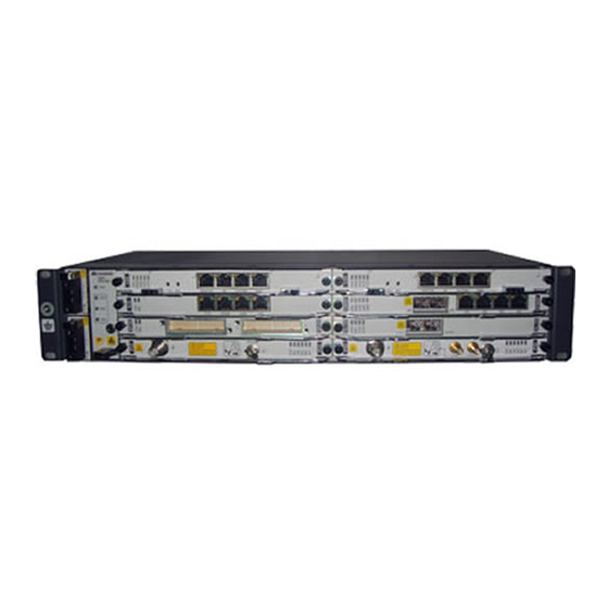
- Page 1 OptiX RTN 950 Radio Transmission System V100 IDU Quick Installation Guide (Indoor) Issue: 01 Date: 2018-10-30 HUAWEI TECHNOLOGIES CO., LTD.
- Page 2 Notice The purchased products, services and features are stipulated by the contract made bet ween Huawei and the customer. All or part of the products, services and features described in this document may not be within the purchase scope or the usage scope. Unless otherwise specified in the contract, all statements, information, and recommendations in this document are provided "AS IS"...
-
Page 3: Installation Process
Installation Process Start Page 2 Precautions Before You Start Instructions and Installing PGND Page18 Precautions for Page 3 Cables Handling Boards Instructions and Pages Installing Power 19 to 20 Cables Precautions for Page 4 Handling Power Cable Terminals Pages Installing E1 Cables 20 to 21 Precautions for Page 5... -
Page 4: Commissioning Process
Commissioning Process Start Powering On the Page 31 Equipment Configuring the NE Page 32 Data (by Using the Web LCT) Pages Aligning the Pages Aligning the Single- 33 to 35 Antennas 33 to 34 Polarized Antennas Checking the Radio Pages Aligning the Dual- Page 35 Link Status... - Page 5 Precautions NOTE This document provides quick guidelines for hardware installation. This document does not describe pre-delivery assembly. This document describes only procedures for onsite installation. CAUTION Power Supply The equipment uses a -48 V/-60 V DC power supply. An AC power supply or a high-voltage power supply may cause equipment damage or even human injuries and therefore is forbidden.
- Page 6 Instructions and Precautions for Handling Boards CAUTION Do not hold a board without hand protection. Wear an ESD wrist strip or ESD gloves before handling a board. Wearing ESD gloves Wearing an ESD strip Holding a board without hand protection CAUTION Hold the front panel of a board with hands.
- Page 7 Instructions and Precautions for Handling Power Cable Terminals Press the front of the red latch. Properly move the red latch outwards. CAUTION Do not pick up the tail end of the red latch by using a finger or a screwdriver to avoid damage.
- Page 8 Precautions for Handling the Toggle Lever Switch •Position and description of the toggle lever switch O: OFF CAUTION Turn the toggle lever switch only after gently pulling it out. I: ON NOTE A dual-channel IF board does not have a toggle lever switch. •Turning on the switch Pull the switch out gently.
- Page 9 Precautions for Handling IDU-side IF Cables (Single- Channel IF Board) CAUTION Connect or disconnect an IF cable only after Do not connect or disconnect an IF cable when the powering off the ODU. ODU is powered on. Power off the ODU. Connect or disconnect the IF cable.
- Page 10 Precautions for Installing IF Cables (Dual-Channel IF Board) CAUTION When installing an IF cable, connect one end of the cable to the ODU and then connect the other end of the cable to the IDU. Connect the IF cable to the IDU. Connect the IF cable to the ODU.
- Page 11 Precautions for Handling IF Boards CAUTION Remove or insert an IF board only after powering off the ODU. Remove the IF board. Insert the IF board. Power off the ODU. Disconnect the IF jumper. Remove or insert the IF board. Skip this step if a dual-channel IF board is concerned.
-
Page 12: Tools For Installation
Tools for Installation Long measuring tape Level Phillips screwdriver Flat-head screwdriver Adjustable w rench Socket w rench Torque w rench Hex key COAX crimping tool Wire clippers Wire stripper RJ45 crimping tool Diagonal pliers Cold press pliers Needle-nose pliers Bayonet w rench Combination pliers File Multimeter... - Page 13 Introduction to the RTN 950 Equipment Ports Input pow er port ODU pow er switch Orderw ire phone port External clock/time port NM/COM port Ethernet service port Optical port External alarm port E1 port NE concatenation port IF port Synchronous/Asynchronous data port NOTE Based on different board configurations, the positions of the actual IDU ports may be different from the...
- Page 14 Installing the RTN 950 Installing the Chassis in the 19-Inch Cabinet Fixing Floating Nuts Floating nut Installation hole NOTE When tightening floating nuts, ensure a minimum of 25 mm space on the left and right sides of the RTN 950 for ventilation.
- Page 15 Installing the Chassis in the Installing PGND Cables Cabinet To the ground point on the column of the cabinet or the indoor ground bar 2.0±0.2 N· M 1.4±0.14 N· M NOTE Install the cable tray if provided. Connect PGND cables by using the removed screws. Installing the Chassis in the ETSI Cabinet Installing Mounting Ears Fixing Floating Nuts...
-
Page 16: Wall-Mounting The Chassis
Installing the Chassis in the Installing PGND Cables Cabinet To the ground point on the column of the cabinet or the indoor ground bar 2.0±0.2 N· M NOTE Connect PGND cables by using the removed screws. Install the cable tray if provided. 1.4±0.14 N·... - Page 17 Installing the Cable Tray Installing Mounting Ears (Optional) NOTE NOTE If the cable tray is provided, install it according to the Rotate mounting ears to 90 degrees and install illustration in the figure. Otherwise, go to Step g. them in the direction shown in the figure. Installing the Cable Tray Installation Effectiveness (Optional)
- Page 18 Marking and Drilling Holes (2) Place the equipment on the wall and then mark the positions of the holes for installing mounting ears. Remove the equipment and drill the holes at the marked positions. Drill 8 mm diameter holes with a depth ranging from 52 mm to 60 mm.
- Page 19 Desk-Mounting the Chassis Installing Plastic Feet Installing PGND Cables Remove mounting ears and install plastic feet. Connect PGND cables by using the removed screws. PGND cable 1.4±0.14 N· M NOTE Plastic foot Do not place any items around the ventilation holes on the two sides of the cabinet to avoid impacts on heat dissipation.
- Page 20 Fixing the E1 Panel Installing PGND Cables on the E1 Panel To the ground point on the column of the cabinet or the indoor ground bar...
-
Page 21: Installing Boards
Installing Boards Guide rail Loosen the screws on the filler panel and remove the filler panel. Hold the ejector levers on the panel with hands and raise them to form an angle of approximately 45 degrees between the ejector levers and the panel. Push the board gently along the guide rail until the board is secure . Lower the two ejector levers of the board. -
Page 22: Installing Power Cables
Installing Power Cables Insert the power cables into the DC connector based on the pin assignment. You do not need to prepare the power cables on site if they were prepared before delivery. CAUTION After fastening a cable, check whether the cable core is exposed outside the power cable connector terminal. - Page 23 Ensure that the circuit breaker of the PDU is set to the OFF state. Insert the DC connector into the power port of the chassis. Ensure that the two groups of power cables are connected to different wiring terminals, and then tighten the screws of the power connector and the chassis. CAUTION PIU boards in 1+1 hot backup mode If an external power box is used, cut off the input of the power box...
- Page 24 Optional: Connecting E1 Cables to the E1 Panel SP3D board Optional: Connecting E1 Cables to the TCU6 Board TCU6 board SP3S board NOTE The TCU6 board, which performs conversion between DB44 ports and RJ45 ports of 6xE1 services, is generally used with the SP3S (120 ohms) board.
- Page 25 Installing Ethernet Service Cables The EFP8, EM6T, EM6TA, EM6F, EM6FA, and EMS6 boards provide the FE ports. The EM6T, EM6TA, EG4, and EG4P boards provide the GE electrical ports. EM6T board NOTE The Ethernet service port supports the MDI/MDI-X adaptive function. Therefore, you can assemble either a crossover cable or a straight-through cable.
- Page 26 Installing IF Jumpers Installing an IF Jumper The ISM6, ISV3, IF1, ISU2, ISX2, IFU2, and IFX2 boards provide the IF port. ODU switch CAUTION Before installing an IF jumper on a single-channel IF board, turn off the ODU switch on the IF board. If an RG-8U IF cable or a 1/2-inch IF cable is used, an IF jumper is required to connect the IF cable and IDU;...
-
Page 27: Installing Fibers
Installing Fibers Precautions CAUTION When installing or maintaining fibers, do not look into the optical port without eye protection. See Figure 1. Coil up the inter-office fibers on the ODF and then route them into the cabinet. Do not coil up external fibers in the cabinet. - Page 28 Installing Fibers The CQ1, SL1D, SL1DA, EM6F, EM6FA, EMS6, EG4, and EG4P boards provide the optical port. SL1D board Installing STM-1e Cables The CQ1, SL1D, and SL1DA boards provide the STM-1e electrical port. SL1D board Installing NM Cables Installing NM Cables (for a Gateway NE) The CSH and CST boards provide the NMS/COM port.
- Page 29 Installing NM Cables (for Multiple Interconnected NEs at a Site) NMS/COM NOTE Assemble a crossover cable or a straight-through cable on site. Ensure that the interconnected network cables do not form a loop and the standby CSH/CSTA board is not connected to another network cable.
- Page 30 Installing External Clock Cables Assembling External Clock Cables Based on the Pin Assignment Color Relationship CLK/TOD1 White/Orange Negative receive end of the external clock Twisted pair Orange Positive receive end of the external clock White/Green External time 1_N Twisted pair Green External time 1_P Negative transmit end of the external clock...
- Page 31 Installing Asynchronous and Synchronous Data Cables Assembling Asynchronous and Synchronous Data Cables Based on the Pin Assignment Pin Assignment Color Relationship Function White/Orange Transmits asynchronous data signals. Twisted pair Orange Grounding Receives asynchronous data signals. White/Green Twisted pair Green Grounding Blue Transmits synchronous data signals (TIP).
- Page 32 Installing External Alarm Cables Assembling External Alarm Cables Based on the Pin Assignment Color Relationship ALMO ALMI White/Orange External alarm signal input 1 Positive alarm signal output 1 Twisted pair Orange Grounding Negative alarm signal output 1 White/Green Positive alarm signal output 2 External alarm signal input 2 Twisted pair Green...
- Page 33 Cable Layout Effectiveness Cable Connections NM Cables Asy nchronous and Sy nchronous Data Cables PGND Cables Ethernet Serv ice Cables Power Cables IF Jumpers Orderwire Phone Cables External Alarm Cables E1 Cables Fibers/STM-1e Cables External Clock Cables NOTE For information about how to install XPIC cables, see the "Installing XPIC Cables" part. Cable Layout Effectiveness...
-
Page 34: Powering On The Equipment
Powering On the Equipment CAUTION Before powering on the equipment, ensure that the installation of the ODU is completed and the ODU switch on the IF board is set to the OFF state. Red indicator: The fan is malfunctioning. Green indicator: The fan is functioning properly. Status Description of Indicators Indicator Status... - Page 35 Configuring NE Data (by Using the Web LCT) CSH board NMS/COM You can use the Web LCT to configure NE data, including basic data of the NE, IF/ODU information of the radio link, parameters for the IF ports, and parameters for the ODU ports.
-
Page 36: Aligning Antennas
Aligning Antennas Aligning Single-Polarized Antennas Determine the azimuth of the antenna according to the installation position and height of the antenna. Adjust the elevation of the antenna to the horizontal position. Connect a multimeter to the RSSI port on the ODU at the local end and measure the voltage value V NOTE The red line of the multimeter is connected to the pin, and the black line of the multimeter is connected to the inner wall (ground pin). - Page 37 Front view of the lines tracked at different elevations of the antenna RSL value of each line 天线不同仰角下扫描路径的正面图 各路径信号值 Adjust the elevation adjustment screw. At the local end, gently adjust the elevation and azimuth until the RSL reaches the peak within the tracked range. Repeat Steps 3 to 4 to ensure that three signal peaks are tracked in both horizontal and vertical directions.
- Page 38 Use a multimeter to measure the RSL (P1) on the RSSI port of the horizontally polarized ODU at the local end. Power on the vertically polarized ODU at the local end. Use a multimeter to measure the RSL on the RSSI port of the vertically polarized ODU.
-
Page 39: Checking The Installation
Checking the Installation What to Check For The chassis must be installed securely in the position as specified in the engineering design documents. Each chassis component does not have any paint drop, damage, or stain. Otherwise, re -paint or clean the component. - Page 40 Appendix Connecting Cables to a Power Cable Connector Obtaining Tools, Cables, and a Power Cable Connector Pow er cable connector One -48 V blue pow er cable One 0 V black ground cable Ruler Diagonal pliers Utility knife Phillips (optional) screwdriver (M3 screw) Peeling Cables...
- Page 41 Appendix Connecting Cables to a Power Cable Connector Connecting Cables to the Power Cable Connector Route a cable into the pow er cable connector. Power Cable Cable Connector Terminal -48 V power cable (blue) 0 V ground cable (black) Fasten the cable. Pull the cable slightly.
- Page 42 HUAWEI TECHNOLOGIES CO., LTD. Huawei Industrial Base Bantian Longgang Shenzhen 518129 People's Republic of China www.huawei.com...