
Related Manuals for Toro MMX-1158H-S


Summary of Contents for Toro MMX-1158H-S
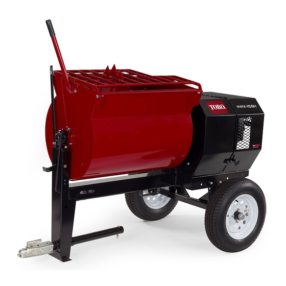
- Page 1 Form No. 3377-527 Rev B MMX-1158H-S Mortar Mixer Model No. 68023C—Serial No. 313000001 and Up G021 119 *3377-527* B Register at www.Toro.com. Original Instructions (EN)
-
Page 2: Introduction
Authorized Toro Service Dealer. product damage. You are responsible for operating the product properly and safely. Genuine Toro spark arresters are approved by the USDA Forestry Service. You may contact Toro directly at www.Toro.com for product and accessory information, help finding a dealer, or to register Important: It is a violation of California Public your product. -
Page 3: Table Of Contents
Contents Introduction ..............2 Safety ................4 Safe Operating Practices........... 4 Safety and Instructional Decals ......... 7 Setup ................8 1 Installing the Dump Handle ........8 2 Installing the Tow Pole .......... 8 3 Installing the Safety Chain ........9 Product Overview ............10 Controls ...............10 Specifications ............12... -
Page 4: Safety
Safety • Never let children or untrained people operate or service the equipment. Local regulations may restrict the age of the operator. Improperly using or maintaining the machine can result • The owner/user can prevent and is responsible for in injury. To reduce the potential for injury, comply with accidents or injuries occurring to people or damage to these safety instructions and always pay attention to the property. - Page 5 Preparation – Ensure that the lug nuts are tight and torqued properly. Become familiar with the safe operation of the equipment, – Ensure that the machine is properly secured. operator controls, and safety signs. • Use only accessories and attachments approved by the Operation manufacturer.
- Page 6 Do not tamper with safety devices. • Chock the tires when storing the machine. • Keep all nuts, bolts, screws, and hose clamps securely tightened. Keep equipment in good condition. • Use only genuine Toro replacement parts to ensure that the original standards are maintained.
-
Page 7: Safety And Instructional Decals
Safety and Instructional Decals Safety decals and instructions are easily visible to the operator and are located near any area of potential danger. Replace any decal that is damaged or lost. 117–2718 125–8175 1. Read the Operator’s Manual for information on greasing the machine. -
Page 8: Setup
Setup Loose Parts Use the chart below to verify that all parts have been shipped. Procedure Description Qty. Dump handle Bolt Install the dump handle. Install the tow pole. Tow pole kit (sold separately) Safety chain (included with the tow pole kit) Install the safety chain. -
Page 9: Installing The Safety Chain
G019804 Figure 4 1. Tow pole 4. Bolt hole 2. Front post 5. Frame fitting 3. Bolt 6. Nut g019883 Figure 5 2. Slide the tow pole forward and align the hole in the 1. Keyhole 3. Safety chain pole with the hole in the frame fitting (Figure 4). 2. -
Page 10: Product Overview
Controls Product Overview Become familiar with all the controls before you start the engine and operate the machine. Clutch Lever The clutch lever (Figure 7) engages and disengages engine power to the paddles. G021 Figure 6 1. Rear cowl 7. Clutch lever 13. - Page 11 Dump Handle Fuel Valve The fuel valve (Figure 11) is located underneath the choke The dump handle (Figure 9) allows the operator to rotate lever. Move the lever for the fuel valve to the On position the drum between the dump position and the mix (upright) before attempting to start the engine.
-
Page 12: Specifications
Operation Important: Before operating, check the fuel and oil levels, and remove debris from the machine. Ensure that the area is clear of people. Preparing to Tow the Machine Important: Ensure that your tow vehicle has towing G021 103 Figure 12 capacity for the weight of the machine. - Page 13 Checking the Tires and Wheels Air Pressure: Max 241 kPa (35 psi) Service Interval: Before each use or daily—Inspect the tires Important: Always check the information and wheels. on the actual tires for the correct air pressure requirement. After each use—Torque the lug nuts to 108 to 122 N-m (80 to 90 ft-lb) after towing.
- Page 14 Hitching a Machine with a Stamped Ball Hitching a Machine with a Forged Ball Coupler Coupler 1. Apply removable thread-locking compound to the 1. Apply chassis grease to the socket of the coupler and the area of the clamp that contacts the ball. Oil the threads of the coupler bolt to prevent the coupler pivot points and sliding surfaces of the coupler with handle from coming loose (Figure 18).
- Page 15 Hitching a Machine with a Pintle Hitch Note: Stow the excess chain inside the bottom of the front post by pushing it into the keyholes. Tow Pole 2. Cross both lengths of chain under the tow pole. 1. Remove the pin from the pintle hitch and open it (Figure 19).
-
Page 16: Extending The Axle
1. Align a jack with an adequate lift height and weight capacity under the axle; refer to Specifications (page 12). 2. Lift the machine until the tires are off the ground. G020828 3. Use a jack stand at each support point on the rear Figure 22 frame extension (Figure 23). -
Page 17: Towing The Machine
Towing the Machine 4. Ensure that the drum is in the mix position (upright). WARNING 5. Ensure that the drum latch is engaged and that the drum does not rotate toward the dump position. Towing the machine at high speed increases the risk of a hitch malfunction and tire failure. -
Page 18: Adding Fuel
Adding Fuel DANGER • For best results, use only clean, fresh, unleaded gasoline In certain conditions during fueling, static with an octane rating of 87 or higher ((R+M)/2 rating electricity can be released causing a spark which method). can ignite the fuel vapors. A fire or explosion from fuel can burn you and others and can damage •... -
Page 19: Checking The Engine Oil Level
Add the correct amount of fuel stabilizer/conditioner to the fuel, and follow the directions of the manufacturer. Note: Fuel stabilizer/conditioner is most effective when mixed with fresh fuel. To minimize the chance of varnish deposits in the fuel system, use fuel stabilizer at all times. Filling the Fuel Tank The fuel tank capacity is 5.3 L (1.4 US gallons). -
Page 20: Starting And Stopping The Engine
30); refer to Engine On/Off Switch (page 11). (Figure 29). 6. Pull the recoil-start handle lightly until you feel Note: Toro Premium Engine Oil is available from resistance, then pull the handle briskly. Return the your Authorized Toro Dealer. recoil-start handle gently (Figure 31). -
Page 21: Controlling The Paddles
Use the clutch lever to control the power transmission to the paddles of the machine. Using the Clutch Lever Move the clutch lever clockwise to engage the clutch, and counterclockwise to disengage the clutch (Figure 32). G019747 Figure 31 Note: If the choke lever is set to the Closed position to start the engine, gradually move the choke lever back toward the Open position as the engine warms up. -
Page 22: Using The Drum
Mixing a Batch of Material in the 8. Release the drum latch and dump the drum; refer to Dumping the Drum (page 22). Machine 1. Ensure that there is no old, loose material in the drum Using the Drum that can contaminate the batch of material; refer to Cleaning the Drum (page 23) and Dumping the Drum (page 22), then return the drum to the upright position. -
Page 23: Adjusting The Paddle Blades
6. After discharging a batch of material, clean the drum; refer to Cleaning the Drum (page 23). Note: This step will clean the paddles and drum between batches and prevent dried material from forming, and contaminating the next batch of material. Cleaning the Drum Important: Do not strike on the drum with a shovel, hammer, or any other device to loosen any accumulated... -
Page 24: Maintenance
Maintenance Important: Before performing any maintenance procedures, first stop the engine, wait 5 minutes to allow all moving parts to come to a complete stop and cool, and disconnect the spark-plug wire. Recommended Maintenance Schedule(s) Maintenance Service Maintenance Procedure Interval •... -
Page 25: Premaintenance Procedures
Premaintenance Procedures Preparing the Machine for Maintenance 1. Park the machine on a level surface. 2. Remove the machine from the tow vehicle. G020752 3. Chock the tires. Figure 38 4. Open the rear cowl; refer to Opening the Cowl (page 17). -
Page 26: Lubrication
Lubrication 2. Pump grease into each fitting as follows: • For the pillow-block bearings, pump 1 shot of grease into each fitting (Figure 40). Lubricating the Bearings and • For the trunnions, pump several shots of grease Seals into each fitting until it starts to ooze out of the bearing housing (Figure 40). -
Page 27: Engine Maintenance
Engine Maintenance Servicing the Air Cleaner Service Interval: Before each use or daily—Inspect the air-cleaner elements. Every 50 hours—Clean the air-cleaner elements. Clean them more frequently in dusty operating conditions. Every 300 hours/Yearly (whichever comes first)—Replace the paper air-cleaner element. Replace it more frequently in dusty operating conditions. -
Page 28: Changing The Engine Oil
Changing the Engine Oil Service Interval: After the first 25 hours Every 100 hours Toro Premium Engine Oil is available from your Authorized Toro Dealer. Important: Use 4-cycle engine oil that meets or exceeds the requirements for API service category SJ, SL, SM, or higher . -
Page 29: Servicing The Spark Plug
Removing the Spark Plug 1. Park the machine on a level surface and turn off the engine; refer to Stopping the Engine (page 21). 2. Ensure that the machine surfaces are cool. 3. Pull the spark-plug wire off the terminal of the spark plug (Figure 45). -
Page 30: Servicing The Spark Arrester
Cleaning the Spark Arrester Service Interval: Every 100 hours Note: A spark arrester is available as an option. If you require a spark arrester, contact your Authorized Toro Service Dealer. Genuine Toro spark arresters are approved by the USDA Forestry Service. -
Page 31: Removing And Installing The Engine
4. Remove the belts; refer to Removing the Belts (page 34). Note: Do not remove the forward hinge bracket. 5. Using a spring-removal tool, (Toro part 92-5771), remove the spring from the anchor bracket on the engine deck (Figure 50). -
Page 32: Fuel System Maintenance
(Figure 51) removed in step 6 of Removing the Engine (page 31). G019333 7. Using a spring-removal tool, (Toro part 92-5771), Figure 53 install the tension spring to the anchor bracket on the engine deck (Figure 50). -
Page 33: Belt Maintenance
Belt Maintenance 10. Move the lever of the fuel valve to the On position (all the way to the right) and check for leaks. If it leaks, replace the O-ring. Servicing the Belts Draining the Fuel Tank Inspecting the Belts 1. -
Page 34: Replacing The Belts
A. Move the clutch lever to the Off position; refer to E. If needed, pivot the engine on the engine deck Controlling the Paddles (page 21). until the engine pulley and the idler pulley are aligned to the straightedge (Figure 57). B. - Page 35 Adjusting the Belt Guide Note: To access the belt guide, remove the divider plate; refer to Removing the Divider Plate (page 25). Guide air gap: 2.5 to 4.0 mm (3/32 to 5/32 inch) 1. Ensure that the clutch lever is in the On position; refer to Controlling the Paddles (page 21).
-
Page 36: Aligning The Pulleys
Checking the Clutch Operation Note: Both pulleys must be aligned flush with the straightedge. Service Interval: Every 40 hours—Check the clutch 3. If the pulleys are not aligned do the following: operation. A. Move the clutch lever to the Off position. Important: The paddles must not rotate in an empty drum when the clutch lever is in the Off position. -
Page 37: Replacing The Light Bulbs
Replacing the Light 2. Remove the lens (Figure 63). 3. Pull the bulb out of the socket (Figure 63). Bulbs 4. Push a new 168 bulb into the socket (Figure 63). 5. Install the lens and the 2 screws (Figure 63). Replacing the Rear-facing Bulbs Note: The left rear-facing bulb also illuminates license plate. -
Page 38: Cleaning
Cleaning Storage Storing the Machine Cleaning the Machine For storage over 30 days, prepare the machine as follows: Regular cleaning and washing will increase the life span of 1. Remove dirt and grime from the external parts of the the machine. Clean the machine after each use, before the entire machine, especially the engine. - Page 39 10. Paint all scratched or bare metal surfaces. Paint is available from your Authorized Toro Dealer. 11. Store the machine in a clean, dry garage or storage area. 12. Cover the machine to protect it and keep it clean.
-
Page 40: Troubleshooting
Troubleshooting Problem Possible Cause Corrective Action The engine will not start. 1. The fuel-valve lever is in the Off 1. Move the fuel-valve lever to the On position. position. 2. The choke is closed 2. Open the choke when starting a hot engine. - Page 41 Notes:...
- Page 42 Notes:...
- Page 43 Notes:...
- Page 44 Toro importer. If all other remedies fail, you may contact us at Toro Warranty Company. Australian Consumer Law: Australian customers will find details relating to the Australian Consumer Law either inside the box or at your local Toro Dealer.