Table of Contents
Advertisement
Quick Links
Register at www.Toro.com.
Original Instructions (EN)
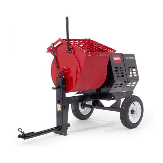
MM-Series Mortar Mixer
Model No. 68013—Serial No. 313000001 and Up
Model No. 68014—Serial No. 313000001 and Up
Model No. 68016—Serial No. 313000001 and Up
Model No. 68017—Serial No. 313000001 and Up
Model No. 68020—Serial No. 313000001 and Up
Model No. 68021—Serial No. 313000001 and Up
Model No. 68024—Serial No. 313000001 and Up
Form No. 3378-860 Rev A
G019552
*3378-860* A
Advertisement
Table of Contents

Related Manuals for Toro MM Series


Summary of Contents for Toro MM Series
- Page 1 Model No. 68016—Serial No. 313000001 and Up Model No. 68017—Serial No. 313000001 and Up Model No. 68020—Serial No. 313000001 and Up Model No. 68021—Serial No. 313000001 and Up Model No. 68024—Serial No. 313000001 and Up G019552 *3378-860* A Register at www.Toro.com. Original Instructions (EN)
-
Page 2: Introduction
You may contact Toro directly at www.Toro.com for product WARNING and accessory information, help finding a dealer, or to register your product. CALIFORNIA Whenever you need service, genuine Toro parts, or additional Proposition 65 Warning information, contact an Authorized Service Dealer or Toro... -
Page 3: Table Of Contents
and Note emphasizes general information worthy of special Servicing the Reduction Case—Belt-drive attention. Models ..............36 Servicing the Gear Case—Gear-case Model....38 Tire Information Belt Maintenance ............39 Servicing the Belts—Belt-drive Models......39 The DOT tire information is located on the side of each tire. Replacing the Belts—Belt-drive Models.....40 This information gives load and speed ratings. -
Page 4: Safety
Safety • Never let children or untrained people operate or service the equipment. Local regulations may restrict the age of the operator. Improperly using or maintaining the machine can result • The owner/user can prevent and is responsible for in injury. To reduce the potential for injury, comply with accidents or injuries to people or damage to property. - Page 5 Preparation – Ensure that the lug nuts are tight and torqued properly. Become familiar with the safe operation of the equipment, – Ensure that the machine is properly secured. operator controls, and safety signs. • Use only accessories and attachments approved by the Operation manufacturer.
- Page 6 Do not tamper with safety devices. • Chock the tires when storing the machine. • Keep all nuts, bolts, screws, and hose clamps securely tightened. Keep equipment in good condition. • Use only genuine Toro replacement parts to ensure that the original standards are maintained.
-
Page 7: Safety And Instructional Decals
Safety and Instructional Decals Safety decals and instructions are easily visible to the operator and are located near any area of potential danger. Replace any decal that is damaged or lost. 117–2718 125–8175 1. Read the Operator’s Manual for information on greasing the machine. -
Page 8: Setup
Setup Loose Parts Use the chart below to verify that all parts have been shipped. Procedure Description Qty. Dump handle Bolt Install the dump handle. Install the tow pole. Tow pole kit (sold separately) Safety chain Install the safety chain. Connecting link Installing the Dump Handle Parts needed for this procedure:... -
Page 9: Installing The Safety Chain
Installing the Tow Pole Installing the Safety Chain Parts needed for this procedure: Parts needed for this procedure: Safety chain Tow pole kit (sold separately) Connecting link Installing the Tow Pole to the Machine Installing the Safety Chain to the Note: The tow pole is purchased separately and includes the Machine nut and bolt needed for installation. -
Page 10: Product Overview
Product Overview G022180 Figure 10 Left side (model 68024) G019773 Figure 8 1. Dump handle 6. Cowl latch 11. Safety-chain Right side (models 68013, 68014, 68016, 68017, 68020, keyhole and 68021) 2. Bag splitter 7. Wheel 12. Front post 1. Rear cowl 7. -
Page 11: Controls
Controls Drum Latch The drum latch secures the drum to the mix position (upright) Become familiar with all the controls before you start the for mixing operations and when transporting the machine. engine and operate the machine. Clutch Lever The clutch lever engages and disengages engine power to the paddles. - Page 12 Engine Controls Choke Lever Use the choke lever (Figure 16) to start a cold engine. Before pulling the recoil-start handle, move the choke lever to the closed position. Once the engine is running, move the choke lever to the open position. Do not use the choke if the engine is already warmed up or the air temperature is high.
-
Page 13: Specifications
Specifications Note: Specifications and design are subject to change without notice. Machine Specifications Model 68013 68014 68016 68017 68020 68021 68024 Batch 0.17 cubic m 0.17 cubic m 0.17 cubic m 0.17 cubic m 0.23 cubic m 0.23 cubic m 0.34 cubic m Capacity (6.0 cubic ft) - Page 14 Checking the Tires and Wheels the appropriate air pressure for the tires as installed at the factory. Service Interval: Before each use or daily—Inspect the tires Important: Always check the information and wheels. on the actual tires for the correct air pressure requirement.
- Page 15 Hitching a Machine with a Stamped Ball Hitching a Machine with a Forged Ball Coupler Coupler 1. Apply removable thread-locking compound to the 1. Apply chassis grease to the socket of the coupler and the area of the clamp that contacts the ball. Oil the threads of the coupler bolt to prevent the coupler pivot points and sliding surfaces of the coupler with handle from coming loose (Figure 23).
- Page 16 Hitching a Machine with a Pintle Hitch 2. Cross both lengths of chain under the tow pole. Tow Pole Note: Crossing the chains decreases the chances of the front of the machine dropping to the ground if the 1. Remove the pin from the pintle hitch and open it hitch does not hold the connection.
-
Page 17: Extending The Axle-Belt-Drive Models
Extending the Axle—Belt-drive Models Models 68013, 68014, 68016, 68017, 68020, and 68021 WARNING The machine is not stable when towing it with the axle in the narrow position. Tow the machine with the axle in the wide position. Important: Adjust the axle to the narrow position only to move the machine through a narrow access point, G020019 such as the gate of a fence or the doorway of a building. -
Page 18: Towing The Machine
Towing the Machine 4. Ensure that the drum is in the mix position (upright). WARNING 5. Ensure that the drum latch is engaged and that the drum does not rotate toward the dump position. Towing the machine at high speed increases the risk of a hitch malfunction and tire failure. -
Page 19: Adding Fuel
2. At the back of the machine, grasp the ring of the latch DANGER and pull it on to the latch anchor on the rear cowl. In certain conditions during fueling, static 3. At the side of the machine, grasp the ring of the latch electricity can be released causing a spark which and pull it onto the latch anchor on the rear cowl. -
Page 20: Checking The Engine Oil Level
Add the correct amount of fuel stabilizer/conditioner to the fuel, and follow the directions of the manufacturer. Note: Fuel stabilizer/conditioner is most effective when mixed with fresh fuel. To minimize the chance of varnish deposits in the fuel system, use fuel stabilizer at all times. Filling the Fuel Tank Model(s) Fuel tank capacity... -
Page 21: Starting And Stopping The Engine
Return the port to raise the level to the Full mark on the dipstick recoil-start handle gently (Figure 35). (Figure 33). Note: Toro Premium Engine Oil is available from your Authorized Toro Dealer. 7. Replace and secure the dipstick (Figure 33). -
Page 22: Controlling The Paddles
Important: Ensure that the paddles do not turn when clutch is in the Off position. Use the clutch lever to control the power transmission to the paddles of the machine. Controlling the Paddles—Belt-drive Models Models 68013, 68014, 68016, 68017, 68020, and 68021 only G019747 Figure 35 Note: If the choke lever is set to the Closed position to start... -
Page 23: Mixing The Material
Controlling the Paddles—Gear-case Mixing a Batch of Material in the Model Machine 1. Ensure that there is no old, loose material in the drum Model 68024 only that can contaminate the batch of material; refer to Cleaning the Drum (page 24) and Dumping the Drum (page 24), then return the drum to the upright position. -
Page 24: Using The Drum
Note: Allow the machine to completely discharge the 8. Release the drum latch and dump the drum; refer to Dumping the Drum (page 24). contents of the drum. 5. Rotate the dump handle clockwise until the drum Using the Drum latch locks the drum in the upright position (Figure 39). - Page 25 G022159 Figure 40 Models 68013, 68016, 68020 G022163 Figure 42 Model 68024 G022161 Figure 41 Models 68014, 68017, 68021...
- Page 26 4. Loosen the nuts and bolts that secure the paddle blades to the paddles (Figure 43, Figure 44, or Figure 45). Note: If necessary, tip the drum to the dump position to access the paddles. G022164 Figure 45 Model 68024 1.
-
Page 27: Maintenance
Maintenance Important: Before performing any maintenance procedures, first stop the engine, wait 5 minutes to allow all moving parts to come to a complete stop and cool, and disconnect the spark-plug wire. Recommended Maintenance Schedule(s) Maintenance Service Maintenance Procedure Interval •... -
Page 28: Premaintenance Procedures
Premaintenance Removing the Divider Plate 1. Unlatch and open the cowl; refer to Opening the Cowl Procedures (page 18). 2. Use a wrench to remove the 4 bolts that secure the Preparing the Machine for divider plate to the front cowl. Maintenance Note: Keep the bolts for installing the divider plate. -
Page 29: Lubrication
Lubrication 2. Pump grease into each fitting as follows: • For the pillow-block bearings, pump 1 shot of grease into each fitting (Figure 49). Lubricating the Bearings and • For the trunnions, pump several shots of grease Seals into each fitting until it starts to ooze out of the bearing housing (Figure 49). -
Page 30: Engine Maintenance
Changing the Engine Oil Service Interval: After the first 25 hours Every 100 hours Toro Premium Engine Oil is available from your Authorized Toro Dealer. Important: Use 4-cycle engine oil that meets or exceeds the requirements for API service category SJ, SL, SM, or higher . - Page 31 Note: Use SAE 10W-30 for general use. You can use the other viscosities shown in the chart when the average temperature in your area is within the indicated range (Figure 51). 5W - 30 / 10W - 30 80 100 F -20 -10 0 20 30 40 C g013375...
-
Page 32: Servicing The Spark Plug
Figure 54 1. Spark plug 2. Wire 4. Clean around the spark plug. 5. Rotate the spark plug counterclockwise using a 13/16 inch (21 mm) spark-plug wrench to remove the plug and the sealing washer (Figure 55). G019746 Figure 53 1. -
Page 33: Servicing The Spark Arrester
Cleaning the Spark Arrester Service Interval: Every 100 hours Note: A spark arrester is available as an option. If you require a spark arrester, contact your Authorized Toro Service Dealer. Genuine Toro spark arresters are approved by the USDA G019300 Forestry Service. -
Page 34: Removing And Installing The Engine
(Figure 61). 40). Note: Do not remove the forward hinge bracket. 6. Using a spring-removal tool (Toro part 92-5771), remove the spring from the anchor bracket on the engine deck (Figure 59). Note: Leave the other end of the spring attached to... -
Page 35: Fuel System Maintenance
(Figure 60) removed in step 7 of Removing the Engine (page 34). G019333 7. Using a spring-removal tool, (Toro part 92-5771), Figure 62 install the tension spring to the anchor bracket on the engine deck (Figure 59). -
Page 36: Drive System Maintenance
Drive System 10. Move the lever of the fuel valve to the On position (all the way to the right) and check for leaks. If it leaks, Maintenance replace the O-ring. Draining the Fuel Tank Servicing the Reduction 1. Remove the engine; refer to Removing the Engine Case—Belt-drive Models (page 34). - Page 37 • If the oil level is below the threads in the oil-level port, add oil as follows: A. Remove the filler bolt and washer from the filler port on the top of the reduction case (Figure 64). B. Slowly add the specified oil into the fill port until the oil level is level with the threads at the bottom of the oil-level port.
-
Page 38: Servicing The Gear Case-Gear-Case Model
55 lb). 7. If the clutch pressure is greater than or less than Checking the Clutch Operation 15 to 30 kg (35 to 55 lb), contact an Authorized Toro Service Dealer. Service Interval: Before each use or daily—Check the clutch operation (Model 68024 only). -
Page 39: Belt Maintenance
Belt Maintenance B. Slowly add the specified oil into the fill port until the oil level is between 1/3 and 1/2 of the sight glass (Figure 68). Servicing the Belts—Belt-drive C. Clean the fill plug. Models D. Apply PTFE thread-sealing tape to the threads of the plug. -
Page 40: Replacing The Belts-Belt-Drive Models
3. If the measured air gap is not within the specified range, adjust the gap as follows: A. Move the clutch lever to the Off position; refer to Controlling the Paddles (page 22). B. Loosen the nuts and bolts that secure the engine to the engine deck (Figure 70). - Page 41 5. Slip the forward belt over the engine pulley and align the belt to the forward pulley groove. 6. Check the belt tension; refer to step 1, step 2, and step 3 in Adjusting the Belt Tension (page 39). 7. Loosely secure the belt guide to the engine (Figure 72) with the bolt that was removed in step 3 of Removing the Belts (page 40).
-
Page 42: Aligning The Pulleys-Belt-Drive Models
Aligning the Important: The belt guide should not contact the belts with the clutch lever in the Pulleys—Belt-drive Models On position. Models 68013, 68014, 68016, 68017, 68020, and 68021 only Note: If the air gap between the belt guide and both belts cannot be attained, then one of the 1. -
Page 43: Cleaning
Cleaning Storage Storing the Machine Cleaning the Machine For storage over 30 days, prepare the machine as follows: Regular cleaning and washing will increase the life span of 1. Remove dirt and grime from the external parts of the the machine. Clean the machine after each use, before the entire machine, especially the engine. - Page 44 10. Paint all scratched or bare metal surfaces. Paint is available from your Authorized Toro Dealer. 11. Store the machine in a clean, dry garage or storage area. 12. Cover the machine to protect it and keep it clean.
-
Page 45: Troubleshooting
Troubleshooting Problem Possible Cause Corrective Action The engine will not start. 1. The fuel-valve lever is in the Off 1. Move the fuel-valve lever to the On position. position. 2. The choke is closed 2. Open the choke when starting a hot engine. - Page 46 Problem Possible Cause Corrective Action The paddles rotate slowly when the clutch 1. The clutch lever is not adjusted 1. Adjust the belt tension. lever is in the On position (models 68013, correctly. 68014, 68016, 68017, 68020, and 68021). The paddles rotate slowly when the clutch 1.
- Page 47 Notes:...
- Page 48 Toro importer. If all other remedies fail, you may contact us at Toro Warranty Company. Australian Consumer Law: Australian customers will find details relating to the Australian Consumer Law either inside the box or at your local Toro Dealer.