Table of Contents
Advertisement
Quick Links
Advertisement
Table of Contents

Related Manuals for Toro MM E-S Series


Summary of Contents for Toro MM E-S Series
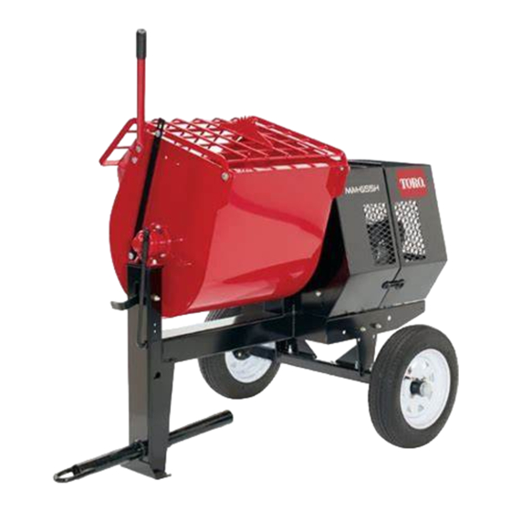
- Page 1 Form No. 3382-958 Rev A MM E-S Series Mortar Mixer Model No. 68012C—Serial No. 314000001 and Up Model No. 68018C—Serial No. 314000001 and Up Model No. 68019C—Serial No. 314000001 and Up G020896 *3382-958* A Register at www.Toro.com. Original Instructions (EN)
-
Page 2: Introduction
You may contact Toro directly at www.Toro.com for product WARNING and accessory information, help finding a dealer, or to register your product. CALIFORNIA Whenever you need service, genuine Toro parts, or additional Proposition 65 Warning information, contact an Authorized Service Dealer or Toro... -
Page 3: Table Of Contents
This manual uses 2 words to highlight information. Cleaning the Machine..........30 Important calls attention to special mechanical information Storage ................31 and Note emphasizes general information worthy of special Storing the Machine..........31 attention. Troubleshooting ............32 Schematics ..............33 The DOT tire information is located on the side of each tire. This information gives load and speed ratings. -
Page 4: Safety
Safety Department of Transportation if in the U.S.) towing safety regulations, before towing the machine. • In order to reduce the possibility of an accident while Improperly using or maintaining the machine can result in injury. To reduce the potential for injury, comply with transporting the machine on public roads, make sure these safety instructions and always pay attention to the the towing vehicle is mechanically sound and in good... - Page 5 Operation – Hard hat • – Respirator or dust mask Never run the machine in a poorly ventilated or enclosed area without proper respiratory protection. Dust from – Face shield or safety glasses materials being mixed can be very harmful to operators –...
- Page 6 Do not tamper with safety devices. • Chock the tires when storing the machine. • Keep all nuts, bolts, screws, and hose clamps securely tightened. Keep equipment in good condition. • Use only genuine Toro replacement parts to ensure that the original standards are maintained.
-
Page 7: Safety And Instructional Decals
Safety and Instructional Decals Safety decals and instructions are easily visible to the operator and are located near any area of potential danger. Replace any decal that is damaged or lost. 125–8175 1. Read the Operator’s Manual for information on greasing the machine. -
Page 8: Setup
Setup Loose Parts Use the chart below to verify that all parts have been shipped. Procedure Description Qty. Dump handle Bolt Install the dump handle. Install the tow pole. Tow pole kit (sold separately) Safety chain Install the safety chain. Connecting link Installing the Dump Handle Parts needed for this procedure:... -
Page 9: Installing The Safety Chain
Note: The tow pole is purchased separately and includes the 1. Form a hook on the end of a bendable piece of rod nut and bolt needed for installation. See a Toro authorized or stiff wire (not included), and insert it through both dealer for the tow pole for your machine. -
Page 10: Product Overview
Drum Latch Product Overview The drum latch secures the drum to the mix position (upright) for mixing operations and when transporting the machine. G020897 Figure 6 G019877 1. Rear cowl 7. Clutch lever 13. Drum Figure 8 2. Front cowl 8. -
Page 11: Specifications
Motor Controls Rotate the On/Off switch to the On position to start and run the motor. Rotate the On/Off switch to the Off position The following motor controls are found on all models: to stop the motor. Figure 10 1. Thermal-overload 3. -
Page 12: Operation
Checking the Tires and Wheels Operation Service Interval: Before each use or daily—Inspect the tires Important: Before operating, remove any debris from and wheels. the machine. Ensure that the area is clear of people. WARNING Preparing to Tow the Machine Failure to maintain correct tire pressure may result in tire failure and loss of control, resulting in Important: Ensure that your tow vehicle has towing... - Page 13 Hitching a Machine with a Stamped Ball the appropriate air pressure for the tires as installed at the factory. Coupler (optional kit) Important: Always check the information 1. Apply chassis grease to the socket of the coupler and on the actual tires for the correct air pressure the area of the clamp that contacts the ball.
- Page 14 Hitching a Machine with a Pintle Hitch Note: Stow the excess chain inside the bottom of the front post by pushing it into the keyholes and latching Coupler (optional kit) the appropriate links into the keyhole slots. 1. Remove the pin from the pintle hitch and open it 2.
-
Page 15: Extending The Axle
Connecting the Lighting Wire Harness Adjusting the Axle Width Connect the electrical plug of the machine with the electrical WARNING plug of the tow vehicle as shown in Figure 20. Mechanical or hydraulic jacks may fail to support the machine and cause serious injury. Use jack stands when supporting the machine. -
Page 16: Towing The Machine
• • Slide each side of the axle inward to the narrow Ensure that all guards are in place and in good condition. position (Figure 22). • Ensure that the paddles are in place and in good • Slide each side of the axle outward to the wide condition. -
Page 17: Opening And Closing The Cowl
Opening and Closing the Cowl Powering the Machine Opening the Cowl Connecting to a Power Source 1. At the side of the machine where the front cowl and DANGER rear cowl meet, grasp the latch and pull it off from the latch anchor on the rear cowl (Figure 23). -
Page 18: Starting And Stopping The Motor
Powering the Machine with a Portable 4. On the side of the junction box for the motor, press the reset button for the thermal-overload protector Generator (Figure 24). When using a portable generator as an electrical source, 5. Connect the electrical plug for the machine to the ensure that it meets the following power-output specifications: power source. -
Page 19: Mixing The Material
Using the Clutch Lever Mixing a Batch of Material in the Machine Move the clutch lever clockwise to engage the clutch, and counterclockwise to disengage the clutch (Figure 25). 1. Ensure that there is no old, loose material in the drum that can contaminate the batch of material;... -
Page 20: Using The Drum
Using the Drum 6. After discharging a batch of material, clean the drum; refer to Cleaning the Drum (page 20). DANGER Note: This step will clean the paddles and drum between batches and prevent dried material from Contact with the mixing paddles could cause forming, and contaminating the next batch of material. - Page 21 3. Loosen the nuts and bolts that secure the paddle blades to the paddles (Figure 29). Note: If necessary, tip the drum to the dump position to access the paddles. G022160 Figure 29 4. Move the paddle blades to the preferred position, and tighten the nuts and bolts to secure the blades to the paddles.
-
Page 22: Maintenance
Maintenance Important: Before performing any maintenance procedures, first stop the motor, wait 5 minutes to allow all moving parts to come to a complete stop and cool, and unplug the power cord. Recommended Maintenance Schedule(s) Maintenance Service Maintenance Procedure Interval •... -
Page 23: Lubrication
Installing the Divider Plate Lubrication 1. Guide the divider plate into position against the front cowl. Lubricating the Bearings and Note: Start with the divider plate rotated slightly Seals counterclockwise, and then rotate it clockwise while lowering it into position. Service Interval: After each use—Lubricate the trunnions. -
Page 24: Lubricating The Motor Bearings
2. Pump grease into each fitting as follows: • For the pillow-block bearings, pump 1 shot of grease into each fitting (Figure 32). • For the trunnions, pump several shots of grease into each fitting until it starts to ooze out of the bearing housing (Figure 32). -
Page 25: Belt Maintenance
Belt Maintenance A. Move the clutch lever to the Off position; refer to Controlling the Paddles (page 18). B. Loosen the nuts and bolts that secure the motor Servicing the Belts to the motor deck (Figure 36). Inspecting the Belts Service Interval: After the first 25 hours—Inspect the belts and adjust as necessary. -
Page 26: Replacing The Belts
G021601 Figure 38 1. Nut 2. Belt guide 4. Slip the forward belt forward and off the idler pulley (Figure 39). g020663 Figure 37 1. Motor pulley 5. Idler shaft 2. Idler pulley 6. Jam nut 3. Belt 7. Setscrew 4. -
Page 27: Aligning The Pulleys
4. Slip the rear belt over the idler pulley and align the belt B. Rotate the belt guide up or down until there is to the rear pulley groove. an air gap of 2.5 to 4.0 mm (3/32 to 5/32 inch) between the guide and each belt (Figure 40). -
Page 28: Drive Chain Maintenance
Drive Chain Maintenance Checking and Adjusting the Drive Chain Service Interval: After the first 10 hours Every 50 hours The drive chain should have 5 to 10 mm (7/32 to 13/32 inch) of flex when applying 6.8 kg (15 lb) of pressure at mid-span. Checking the Drive-chain Tension 1. -
Page 29: Replacing The Light Bulbs
Replacing the Light Bulbs Replacing the Rear-facing Bulbs Note: The left rear-facing bulb also illuminates license plate. 1. Use a screwdriver to remove the 4 screws from the large square lens on the light (Figure 45). G021602 Figure 43 1. Drive chain 3. -
Page 30: Cleaning The Machine
Cleaning 2. Remove the lens (Figure 46). 3. Pull the bulb out of the socket (Figure 46). Cleaning the Machine 4. Push a new 168 bulb into the socket (Figure 46). 5. Install the lens and the 2 screws (Figure 46). Regular cleaning and washing will increase the life span of the machine. -
Page 31: Important Calls Attention To Special Mechanical Information Storage
5. Paint all scratched or bare metal surfaces with paint from your Authorized Toro Dealer. 6. Store the machine in a clean, dry garage or storage area. 7. Cover the machine to protect it and keep it clean. -
Page 32: Troubleshooting
Troubleshooting Problem Possible Cause Corrective Action The electric motor will not start. 1. The connector for the machine is not 1. Plug the connector into a socket or plugged into a power source. an extension cord from an electrical source. 2. -
Page 33: Schematics
Schematics G021587 Electric Motor Schematic (Rev. A) - Page 34 Notes:...
- Page 35 Notes:...
- Page 36 Toro importer. If all other remedies fail, you may contact us at Toro Warranty Company. Australian Consumer Law: Australian customers will find details relating to the Australian Consumer Law either inside the box or at your local Toro Dealer.