Table of Contents
Advertisement
Quick Links
Advertisement
Table of Contents

Related Manuals for ABB Power Break II


Summary of Contents for ABB Power Break II
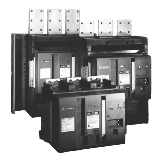
- Page 1 DEH40380 User’s Guide Power Break® II Switches 800–4000 A Frames, 240–600 Vac...
- Page 2 Getting Started Since this switch is available in a variety of configurations, please take a moment to compare the catalog number of your purchased switch with the catalog number key below. Installation of an incorrect switch could result in misapplication, lack of system coordination, or reduced system selectivity.
- Page 3 Features may be described herein that are not present in all hardware and software systems. ABB assumes no obligation of notice to holders of this document with respect to changes subsequently made.
-
Page 4: Table Of Contents
Table of Contents Chapter 1. Introduction 1 Overview........................2 Receiving the Switch....................Storage........................3 Preparation for Installation..................Bolted Electrical Connections................Panel Cutouts and Clearances................Accessory Installation................... 1-4 Switch Installation...................... 3 Chapter 2. Operation 1 Standard Features......................4 2 Operating Instructions....................4 Sequence of Operations.................. - Page 5 Table of Contents 3-10 Key Interlock Mounting Provision............... Operation......................3-11 Mechanical Counter.................... 3-12 Auxiliary Switch Module..................Operation......................3-13 Door Interlock...................... Operation......................3-14 Push Button Cover....................Operation......................Chapter 4. Trouble-Shooting Guide ......................
- Page 6 List of Figures 1. Locations of the front-panel escutcheon cutout and mounting holes, 800–2000 A frames..........................2. Locations of the front-panel escutcheon cutout and monting plate, 2500–4000 A frames..........................3. Locations of the 1 /4–20 x 3 /8-inch deep screw inserts for mounting the switch in equipment, 800–2000 A frames..
- Page 7 1. Weights of the various switch frame sizes, with and without a motor operator......2. Bolt sizes and mounting torques for bus connections..................3. Sequence of operations that may be performed with Power Break II circuit switches..............................
-
Page 8: Chapter 1. Introduction
Chapter 1. Introduction 1-1 Overview Power Break® II insulated-case switches are designed to serve The switch should be stored in a clean location, free from low-voltage power circuits and equipment. They are available corrosive gases or fumes. In particular, protect the switch with and EntelliGuard®... -
Page 9: Accessory Installation
Chapter 1. Introduction Because of arc chamber venting, the minimum through-air distance from the top of the switch’s molded case to grounded metal for 800–2000 A switches is 4.50 inches [114 mm] in an area 5.31 inches x 16.00 inches [135 mm x 406 mm], centered over the vent screens. -
Page 10: Switch Installation
Chapter 1. Introduction — — Figure 4 . Locations of the –16 x -inch deep screw inserts for mounting the switch in Figure 2. Locations of the front-panel escutcheon cutout and mounting plate, 2500–4000 A frames. equipment, 2500–3000 A back-connected frames 1-4 Switch Installation Ensure that all accessory connections are secure. -
Page 11: Chapter 2. Operation
Chapter 2. Operation 2-1 Standard Features Power Break II switches are equipped with the following standard features. The letters are keyed to the switch photographs in Figures 6 and 7. ON – Red Indicator: OFF – Green Indicator: CHARGED – Yellow DISCHARGED –... -
Page 12: Sequence Of Operations That May Be Performed With Power Break
Charged Contacts may be opened — Table 3. Sequence of operations that may be performed with Power Break II switches. Closing the Switch CAUTION: If the switch latch is held in the tripped position Close the switch contacts with either of the following... -
Page 13: Additional Instructions For Motor-Operated Switches
Chapter 2. Operation Opening the Switch Open the switch contacts with either of the following methods: • Depress the OFF button on the front of the switch. • Energize the (optional) Shunt Trip or Shunt Trip with Lockout accessory or de-energize the (optional) Undervoltage Release accessory. -
Page 14: Trip Unit Setup
Chapter 2. Operation 2-3 Control Unit Setup See DEH4567 for detailed instructions on setting up EntelliGuard® Control Units. — Figure 9. Terminal block mounted on the right side of the switch. Terminal Terminal Motor Operator + Motor Operator – Remote Charge Remote Charge Remote Close + Remote Close –... -
Page 15: Chapter 3. Accessory Operation
Chapter 3. Accessory Operation Max. Following are the operation procedures for each of the Lugs Wires Wire Frame Max. available switch accessories. See the user guides supplied with Range Size (A) Amps Cat. No. Pole the accessories for installation and removal. TSLUG08 3-1 Lug and Adapter Kits TSLUG12... -
Page 16: T-Studs
Chapter 3. Accessory Operation T-Studs Frame Lug Odering Information T-Studs bolt directly to the line or load terminals of the switch. Cat. No. (Per Line or Load Side) Order one T-Stud per line or load pole. T-Stud catalog numbers and ratings are listed in Table 7. 9 TPLUG108 Lugs TPLUGA08 or 9 Crimp Lugs... -
Page 17: Plug-In Accessory Compartment
Chapter 3. Accessory Operation 3-2 Plug-In Accessory Compartment The catalog numbers for the Bell Alarm–Alarm Only are listed in Table 9. For installation instructions see Several of the accessories are installed in the accessory GEH6275. compartment on the front of the switch. Figure 10 illustrates Catalog No. -
Page 18: Operation
Chapter 3. Accessory Operation when the Bell Alarm with Lockout reset button is firmly The EntelliGuard® Control Unit activates the Bell Alarm with pressed. Lockout for ground fault protection trips only. The catalog numbers for the Bell Alarm with Lockout are listed in Table 10. -
Page 19: Shunt Trip
Chapter 3. Accessory Operation 3-5 Shunt Trip Operation Apply control voltage to terminals 31 and 32 of the terminal The Shunt Trip module, shown in Figure 15, allows the strip on the right side of the switch to open the switch. The switch to be tripped electrically from a remote location. -
Page 20: Operation
Chapter 3. Accessory Operation Peak Catalog Voltage Nominal RMS Inrush Number Rating Current, mA Current, A SPSTL012 12 Vdc 24 Vac SPSTL024 24 Vdc 48 Vac SPSTL048 48 Vdc 120 Vac SPSTL120 — 125 Vdc Figure 17. Undervoltage Release module. SPSTL208 208 Vac The catalog numbers for the UVR for various voltage... -
Page 21: Motor Operator Mechanism
Chapter 3. Accessory Operation 3-8 Motor Operator Mechanism CAUTION: Do not wire switches for both automatic charge and automatic close. The Motor Operator Mechanism, shown in Figure 18, provides a means of remotely or automatically charging the springs ATTENTION: Ne pas câbler les interrupteurs pour lestous that close the switch. -
Page 22: Key Interlock Mounting Provision
3-10 Key Interlock Mounting Provision The Key Interlock Mounting Provision provides mounting for one to four key locks. The ABB catalog number is SPK4. The key locks must have a zero extension when the bolt is withdrawn with 0.75-inch extension when the bolt is extended. -
Page 23: Mechanical Counter
Chapter 3. Accessory Operation 3-11 Mechanical Counter The Mechanical Counter, shown in Figure 21, counts the number of times the switch is closed. The catalog number of the Mechanical Counter is SPCOUNTER. For installation instructions see GEH6280. — Figure 22. Auxiliary Switch Module with 12 switches. —... -
Page 24: Door Interlock
Chapter 3. Accessory Operation Terminal (upper) Terminal (lower) 1 Auxiliary 12 A 19 Auxiliary 11 A 2 Auxiliary 12 B 20 Auxiliary 11 B 3 Auxiliary 12 common 21 Auxiliary 11 common 4 Auxiliary 10 A 22 Auxiliary 9 A 5 Auxiliary 10 B 23 Auxiliary 9 B 24 Auxiliary 9 common... -
Page 25: Chapter 4. Trouble-Shooting Guide
Chapter 4 – Trouble-Shooting Guide The following guide is provided for trouble-shooting and isolating common problems. It does not cover every possible situation. Contact the Customer Support Center at 800-843-3742 if any problem is not resolved by these procedures. Symptom Possible Cause Corrective Action 1. - Page 26 For any other problems related to Power Break II accessories, consult the corresponding User’s Guide: • GEH6271, Draw-Out 800–4000 Ampere Frames • GEH6272, Draw-Out Substructure, 800–4000 Ampere • GEH6274, Auxiliary Switch Module • GEH6275, Bell Alarm – Alarm Only • GEH6276, Door Interlock •...