ABB SensyMaster FMT230 Commissioning Instruction
Thermal mass flowmeter
Hide thumbs
Also See for SensyMaster FMT230:
- Commissioning instruction (28 pages) ,
- Operating instruction (112 pages)
Table of Contents
Advertisement
Quick Links
—
A B B M E A S U R E M E N T & A N A L Y T I C S | C O M M I S S I O N I N G I N S T R U C T I O N | C I / F M T 2 3 0 / 2 5 0 - E N R E V . B
SensyMaster FMT230, FMT250
Thermal mass flowmeter
—
Introduction
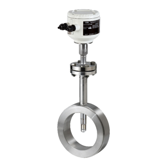
SensyMaster FMT230
SensyMaster FMT250
The SensyMaster FMT230 is a top-quality cost-
effective solution for the precise and direct
dynamic mass flow measurement of gases at low
and medium operating pressure levels. The model
is delivered preconfigured, ready for use by OEM
customers.
In addition, the FMT250 offers the highest level of
accuracy and extended functionality for
demanding industrial applications.
Precise and dynamic direct mass
flow measurement of gas in OEM
applications
Measurement made easy
Additional Information
Additional documentation on SensyMaster FMT230,
FMT250 is available for download free of charge at
www.abb.com/flow.
Alternatively simply scan this code:
Advertisement
Table of Contents

Related Manuals for ABB SensyMaster FMT230


Summary of Contents for ABB SensyMaster FMT230
- Page 1 Introduction Additional Information SensyMaster FMT230 SensyMaster FMT250 The SensyMaster FMT230 is a top-quality cost- Additional documentation on SensyMaster FMT230, effective solution for the precise and direct FMT250 is available for download free of charge at dynamic mass flow measurement of gases at low www.abb.com/flow.
-
Page 2: Table Of Contents
FMT230, FMT250 THERMAL MASS FLOWMETER | CI/FMT230/250-EN REV. B Table of contents Product identification ..........20 Safety ................4 Name plate ................20 General information and instructions ........4 Plates and symbols ..............20 Warnings ..................4 Intended use ................4 Transport and storage .......... - Page 3 FMT230, FMT250 THERMAL MASS FLOWMETER | CI/FMT230/250-EN REV. B Electrical connections ..........39 Safety instructions ..............39 Installing the connection cables ......... 40 Opening and closing the housing ........40 Position of the terminals ............41 Pin assignment ............... 41 Electrical data for inputs and outputs .......
-
Page 4: Safety
FMT230, FMT250 THERMAL MASS FLOWMETER | CI/FMT230/250-EN REV. B 1 Safety Warnings General information and instructions The warnings in these instructions are structured as follows: These instructions are an important part of the product and must be retained for future reference. DANGER Installation, commissioning, and maintenance of the product may only be performed by trained specialist personnel who have... -
Page 5: Improper Use
/ or theft of data or information. adversely affected during the operating time. ABB Automation Products GmbH and its affiliates are not liable • Media containing chloride in particular can cause... -
Page 6: Use In Potentially Explosive Atmospheres In Accordance With Atex And Iecex
T and the ambient medium • ABB reserves the right to modify the Ex-marking. Refer to the temperature T amb. name plate for the exact marking. For the electrical connection of the device, use only cables with sufficient temperature resistance in accordance with the following table. -
Page 7: Environmental And Process Conditions For Model Fmt2Xx
FMT230, FMT250 THERMAL MASS FLOWMETER | CI/FMT230/250-EN REV. B Environmental and process conditions for model FMT2xx… Ambient temperature T −20 to 70 °C (−4 to 158 °F) amb. Measuring medium temperature T −20 to 150 °C (−4 to 302 °F) medium IP rating / NEMA rating IP 65, IP 67 / NEMA 4X,Type 4X... -
Page 8: Electrical Data
FMT230, FMT250 THERMAL MASS FLOWMETER | CI/FMT230/250-EN REV. B … 2 Use in potentially explosive atmospheres in accordance with ATEX and IECEx Electrical data Modbus outputs and digital outputs Model: FMT2xx-A1…, FMT2xx-A2…, FMT2xx-A3… Operating values Type of protection (general) ‘Ex ec’ ‘Ex e’... -
Page 9: Installation Instructions
The information in the installation diagram 3kxf000094G0009 on page 53 must be observed. Note Spare parts can be ordered from ABB Service. Use in areas exposed to combustible dust www.abb.com/contacts When using the device in areas exposed to combustible dusts (dust ignition), the following points must be observed: •... -
Page 10: Cable Entries
Perform grounding of the device in accordance with Pin assignment on page 41. 1 Warning – Do not open in a flammable or potentially explosive atmosphere. 1 WARNING! – Danger due to electrostatic discharge. Figure 1: Warning signs on the device Repair Contact ABB before commencing repair work. -
Page 11: Changing The Type Of Protection
FMT230, FMT250 THERMAL MASS FLOWMETER | CI/FMT230/250-EN REV. B Changing the type of protection If you are installing in Zone 1 / Div. 1, the Modbus interface and digital outputs of models FMT230/250 can be operated with different types of protection: •... -
Page 12: Use In Potentially Explosive Atmospheres In Accordance With Fm And Csa
Depending on the design, a specific marking in accordance with FM applies. • ABB reserves the right to modify the Ex-marking. Refer to the name plate for the exact marking. Designation for model FMT2xx-F2… in Division 2 Designation for model FMT2xx-F1… in Division 1... -
Page 13: Temperature Data
Note The signal cable supplied by ABB can be used without restrictions up to an ambient temperature of ≤ 80 °C (≤ 176 °F). - Page 14 FMT230, FMT250 THERMAL MASS FLOWMETER | CI/FMT230/250-EN REV. B … 3 Use in potentially explosive atmospheres in accordance with FM and CSA … Temperature data Measuring medium temperature (Ex data) for model FMT2x0-F1… in Class I Division 1 and Class II Division 1 The table shows the maximum permissible measuring medium temperature as a function of ambient temperature and temperature class.
-
Page 15: Electrical Data
FMT230, FMT250 THERMAL MASS FLOWMETER | CI/FMT230/250-EN REV. B Electrical data Modbus outputs and digital outputs Model: FMT2xx-F1…, FMT2xx-F2… Operating Type of protection values (general) (Div. 2, Zone 2) (Div. 1, Zone 1) (Div. 1, Zone 1) Outputs [V] I [mA] [V] I [mA]... -
Page 16: Installation Instructions
The process temperature of the connected line can up- See also Opening and closing the housing on page 40. scale 85 °C (185 °F). Only original spare parts must be used to seal the housing. Note Spare parts can be ordered from ABB Service. www.abb.com/contacts... -
Page 17: Cable Entries
All cable (conduits) should be sealed from the device within a distance of 18 in (457 mm). Figure 2: Cable entry ABB flowmeters are designed for the worldwide industrial The devices are delivered with ½ in NPT threads with transport market and are suitable for functions such as the measurement protection plugs. -
Page 18: Operating Instructions
FMT230, FMT250 THERMAL MASS FLOWMETER | CI/FMT230/250-EN REV. B … 3 Use in potentially explosive atmospheres in accordance with FM and CSA Operating instructions Protection against electrostatic discharges Repair Contact the manufacturer for specific flamepath joint details DANGER during repair of flameproof “XP” apparatus. Risk of explosion! The painted surface of the device can store electrostatic charges. -
Page 19: Changing The Type Of Protection
FMT230, FMT250 THERMAL MASS FLOWMETER | CI/FMT230/250-EN REV. B Changing the type of protection The Modbus interface and the digital outputs of the models FMT230/250 can be operated with different types of protection: • When connecting to an intrinsically safe circuit in Div. 1 as an intrinsically safe device (IS). •... -
Page 20: Product Identification
FMT230, FMT250 THERMAL MASS FLOWMETER | CI/FMT230/250-EN REV. B 4 Product identification Name plate Plates and symbols Note Devices which are approved for use in potentially explosive The name plates displayed are examples. The device atmospheres have an additional warning plate. identification plates affixed to the device can differ from this representation. -
Page 21: Transport And Storage
• Avoid storing the device in direct sunlight. All devices delivered to ABB must be free from any hazardous • In principle, the devices may be stored for an unlimited materials (acids, alkalis, solvents, etc.). period. However, the warranty conditions stipulated in the order confirmation of the supplier apply. -
Page 22: Installation
FMT230, FMT250 THERMAL MASS FLOWMETER | CI/FMT230/250-EN REV. B 6 Installation Installation conditions Safety instructions Installation location and assembly DANGER Note the following points when selecting the installation location and when mounting the sensor: Danger to life due to piping under pressure! •... -
Page 23: Inlet And Outlet Sections
FMT230, FMT250 THERMAL MASS FLOWMETER | CI/FMT230/250-EN REV. B Inlet and outlet sections Installation at high ambient temperatures The figures below show the recommended inlet and outlet sections for various installations. Figure 7: Mounting position at high ambient temperatures Under high but permissible ambient temperatures, avoid additional thermal stress from heat convection or radiation, since these sources of heat may exceed the permissible ambient temperature on the equipment surface. -
Page 24: Ambient Conditions
FMT230, FMT250 THERMAL MASS FLOWMETER | CI/FMT230/250-EN REV. B … 6 Installation Ambient conditions Ambient temperature Maximum operating pressure • Standard: −20 to 70 °C (−4 to 158 °F) • Optional (in preparation): −40 to 70 °C (−40 to 158 °F) Sensor connection Maximum measuring medium pressure P... -
Page 25: Material Loads For Process Connections
FMT230, FMT250 THERMAL MASS FLOWMETER | CI/FMT230/250-EN REV. B Assembly of the pipe component When installing the pipe components, observe the following Material loads for process connections points: DIN and ASME flanges • During installation, it is important to ensure that the flow direction corresponds to the attached label. -
Page 26: Wafer Type Design (Fmt091) And Partial Measuring Section (Fmt092)
FMT230, FMT250 THERMAL MASS FLOWMETER | CI/FMT230/250-EN REV. B … 6 Installation Wafer type design (FMT091) and partial measuring section (FMT092) 3. Use the appropriate screws for the holes. 4. Slightly grease the threaded nuts. 5. Tighten the nuts in a crosswise manner in accordance with the figure. -
Page 27: Assembly Of The Welding Adapter With Flange Or Threaded Connector
FMT230, FMT250 THERMAL MASS FLOWMETER | CI/FMT230/250-EN REV. B Assembly of the welding adapter with flange or threaded connector Welding adapter with flange connector Dimensions in mm (in) 1 Centering pin 3 Connection flange DN 25 (1 in) 2 Groove for O-ring 4 Flow direction Figure 15: Dimensions in mm (in) h –... - Page 28 FMT230, FMT250 THERMAL MASS FLOWMETER | CI/FMT230/250-EN REV. B … 6 Installation … Assembly of the welding adapter with flange or threaded connector Dimensions in mm (in) 1 Centering pin 3 Connection flange DN 25 (1 in) 2 Groove for O-ring 4 Flow direction Figure 16: Dimensions in mm (in) h –...
-
Page 29: Welding Adapter With Threaded Connection In Accordance With Din 11851
FMT230, FMT250 THERMAL MASS FLOWMETER | CI/FMT230/250-EN REV. B Welding adapter with threaded connection in accordance with DIN 11851 Dimensions in mm (in) 1 Union nut 3 Centering pin 2 Flow direction Figure 17: Dimensions in mm (in) -
Page 30: Mounting
FMT230, FMT250 THERMAL MASS FLOWMETER | CI/FMT230/250-EN REV. B … 6 Installation … Assembly of the welding adapter with flange or threaded connector Mounting Consider the following points when installing the welding dater Additional instructions for welding adapter with ball valve in the piping: DANGER •... -
Page 31: Assembly Of The Welding Adapter With Compression Ring Fitting
FMT230, FMT250 THERMAL MASS FLOWMETER | CI/FMT230/250-EN REV. B Assembly of the welding adapter with compression ring fitting All dimensions in mm (in) 1 Compression fitting 2 Welding tube for the compression fitting Figure 18: Welding adapter with compression fitting h –... -
Page 32: Mounting
FMT230, FMT250 THERMAL MASS FLOWMETER | CI/FMT230/250-EN REV. B … 6 Installation … Assembly of the welding adapter with compression ring fitting Mounting Calculation of mounting dimensions Preparing the sensor DANGER Fire hazard in oxygen applications Fire hazard in oxygen applications due to the use of unapproved thread sealing compound. - Page 33 FMT230, FMT250 THERMAL MASS FLOWMETER | CI/FMT230/250-EN REV. B First installation of the sensor When mounting the sensor, a distinction is made between first installation and reinstallation. We will address first installation below. Please also follow the ‘An Installer’s Pocket Guide for Swagelok® Tube Fittings –...
- Page 34 FMT230, FMT250 THERMAL MASS FLOWMETER | CI/FMT230/250-EN REV. B … 6 Installation … Assembly of the welding adapter with compression ring fitting Disassembly and reinstallation of the sensor When mounting the sensor, a distinction is made between first NOTICE installation and reinstallation. We will address reinstallation Damage to the device below.
-
Page 35: Assembly Of The Welding Adapter With Hot Tap Fitting
FMT230, FMT250 THERMAL MASS FLOWMETER | CI/FMT230/250-EN REV. B Assembly of the welding adapter with hot tap fitting DANGER Welding design DANGER Explosion hazard Explosion hazard during installation or operation of the Danger to life due to improper installation! integrated hot tap fitting in potentially explosive Do not shorten hot tap fitting components or interfere with atmospheres. - Page 36 FMT230, FMT250 THERMAL MASS FLOWMETER | CI/FMT230/250-EN REV. B … 6 Installation … Assembly of the welding adapter with hot tap fitting Calculation of the installation length X and installation depth Y − − inch X Outside length of the integrated changing device Y Installation depth of the integrated changing device h Sensor length D Outside diameter of the pipeline...
-
Page 37: Installing The Sensor
FMT230, FMT250 THERMAL MASS FLOWMETER | CI/FMT230/250-EN REV. B Installing the sensor When installing the sensor, observe the following points: Installing the sensor: • Installation in the pipe component or welding adapter is 1. Place the supplied O-ring in the groove of the sensor only possible if the sensor data matches the measuring connection. -
Page 38: Installation / Disassembly In Connection With The Hot Tap Fitting
FMT230, FMT250 THERMAL MASS FLOWMETER | CI/FMT230/250-EN REV. B … 6 Installation … Installing the sensor Installation / Disassembly in connection with the hot tap fitting DANGER Danger to life due to piping under pressure! If the changing device is in the measurement position during disassembly of the sensor, this may pose a danger to life due to the possibility of the sensor being ejected. -
Page 39: Electrical Connections
FMT230, FMT250 THERMAL MASS FLOWMETER | CI/FMT230/250-EN REV. B 7 Electrical connections Safety instructions DANGER Installation of the sensor during operation Danger of explosion if the device is operated with the Note transmitter housing or terminal box open! The changing device must be in the disassembly position before Before opening the transmitter housing or the terminal box, disassembling the sensor, the sensor connection is sealed. -
Page 40: Installing The Connection Cables
FMT230, FMT250 THERMAL MASS FLOWMETER | CI/FMT230/250-EN REV. B … 7 Electrical connections Installing the connection cables Opening and closing the housing WARNING Ensure that a drip loop (water trap) is used when installing the connecting cables for the sensor. Risk of injury due to live parts! When the housing is open, contact protection is not provided and EMC protection is limited. -
Page 41: Position Of The Terminals
FMT230, FMT250 THERMAL MASS FLOWMETER | CI/FMT230/250-EN REV. B Position of the terminals Pin assignment Figure 29: Electrical connection PA = functional ground (potential equalization) Connections for the power supply DC voltage Terminal Function / comments 2− − Connections for the outputs Terminal Function / comments A / B... - Page 42 FMT230, FMT250 THERMAL MASS FLOWMETER | CI/FMT230/250-EN REV. B … 7 Electrical connections … Electrical data for inputs and outputs Digital output 41 / 42, 51 / 52 Can be configured via Modbus. Binary output (passive) Terminals 41 / 42, 51 / 52 Output ‘closed’...
-
Page 43: Modbus® Communication
FMT230, FMT250 THERMAL MASS FLOWMETER | CI/FMT230/250-EN REV. B Modbus® communication Note The Modbus® protocol is an unsecured protocol, as such the intended application should be assessed to ensure that these protocols are suitable before implementation. Modbus is an open standard owned and administrated by an independent group of device manufacturers styled the Modbus Organization (www.modbus.org). -
Page 44: Connection On The Device
FMT230, FMT250 THERMAL MASS FLOWMETER | CI/FMT230/250-EN REV. B … 7 Electrical connections Connection on the device Potential equalization Figure 32: Connection to device Connecting integral mount design Observe the following points when connecting to the power Perform steps supply: •... -
Page 45: Commissioning And Operation
FMT230, FMT250 THERMAL MASS FLOWMETER | CI/FMT230/250-EN REV. B 8 Commissioning and operation Safety instructions Write-protection switch, service LED and local operator interface DANGER Danger of explosion if the device is operated with the transmitter housing or terminal box open! Before opening the transmitter housing or the terminal box, note the following points: •... -
Page 46: Checks Prior To Commissioning
FMT230, FMT250 THERMAL MASS FLOWMETER | CI/FMT230/250-EN REV. B … 8 Commissioning and operation Checks prior to commissioning Parameterization of the device Note The following points must be checked before commissioning the For detailed information on the operation and parameterization device: Correct wiring in accordance with Electrical connections of the device, consult the associated operating instructions (OI)! - Page 47 (see Figure 34, item The manufacturer code (ABB = 0x1A) and the device code (FMT = 0x27) must be written to If the Modbus address is not known, the Modbus Slave ID can be register 65522.
-
Page 48: Parameterization Via The Local Operating Interface
Installation of the software and connection to the flowmeter: 1. Install ABB Field Information Manager (FIM). 2. Unpack the ABB FDI package into the c:\temp folder. 1 Local operating interface 3 PC / Notebook 3. Connect the flowmeter with the PC / laptop, see Connection... -
Page 49: Maintenance
FMT230, FMT250 THERMAL MASS FLOWMETER | CI/FMT230/250-EN REV. B 9 Maintenance Safety instructions DANGER Danger of explosion if the device is operated with the transmitter housing or terminal box open! Before opening the transmitter housing or the terminal box, Figure 39: Select FIM – COM-Port note the following points: 8. -
Page 50: Recycling And Disposal
FMT230, FMT250 THERMAL MASS FLOWMETER | CI/FMT230/250-EN REV. B 10 Recycling and disposal Dismounting Disposal Note WARNING Products that are marked with the adjacent symbol may not be disposed of as unsorted municipal waste Risk of injury due to process conditions. (domestic waste). -
Page 51: Specification
FMT230, FMT250 THERMAL MASS FLOWMETER | CI/FMT230/250-EN REV. B 11 Specification Note The device data sheet is available in the ABB download area at www.abb.com/flow. 12 Additional documents Note All documentation, declarations of conformity, and certificates are available in ABB's download area. -
Page 52: Appendix
FMT230, FMT250 THERMAL MASS FLOWMETER | CI/FMT230/250-EN REV. B 13 Appendix Return form Statement on the contamination of devices and components Repair and/or maintenance work will only be performed on devices and components if a statement form has been completed and submitted. -
Page 53: Fmt200 Installation Diagram 3Kxf000094G0009
FMT230, FMT250 THERMAL MASS FLOWMETER | CI/FMT230/250-EN REV. B FMT200 Installation diagram 3kxf000094G0009 Page 1 of 5... - Page 54 FMT230, FMT250 THERMAL MASS FLOWMETER | CI/FMT230/250-EN REV. B … 13 Appendix … FMT200 Installation diagram 3kxf000094G0009 Page 2 of 5...
- Page 55 FMT230, FMT250 THERMAL MASS FLOWMETER | CI/FMT230/250-EN REV. B Page 3 of 5...
- Page 56 FMT230, FMT250 THERMAL MASS FLOWMETER | CI/FMT230/250-EN REV. B … 13 Appendix … FMT200 Installation diagram 3kxf000094G0009 Page 4 of 5...
- Page 57 FMT230, FMT250 THERMAL MASS FLOWMETER | CI/FMT230/250-EN REV. B Page 5 of 5...
- Page 58 FMT230, FMT250 THERMAL MASS FLOWMETER | CI/FMT230/250-EN REV. B Trademarks Modbus is a registered trademark of Schneider Automation Inc. Swagelok is a registered trademark of the Swagelok Company...
- Page 59 FMT230, FMT250 THERMAL MASS FLOWMETER | CI/FMT230/250-EN REV. B Notes...
- Page 60 We reserve the right to make technical changes or modify the contents of this document without prior notice. With regard to purchase orders, the agreed particulars shall prevail. ABB does not accept any responsibility whatsoever for potential errors or possible lack of information in this document.