ABB SensyMaster FMT230 Commissioning Instruction
Hide thumbs
Also See for SensyMaster FMT230:
- Commissioning instruction (60 pages) ,
- Operating instruction (112 pages)
Table of Contents
Advertisement
Quick Links
—
A B B M E A S U R E M E N T & A N A L Y T I C S | C O M M I S S I O N I N G I N S T R U C T I O N
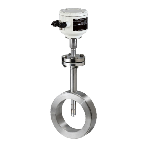
SensyMaster FMT230, FMT250
Thermal mass flowmeter
Measurement made easy
Additional Information
Additional documentation on SensyMaster
FMT230, FMT250 is available free of charge for
downloading at www.abb.com/flow.
Alternatively simply scan this code:
Advertisement
Table of Contents

Related Manuals for ABB SensyMaster FMT230


Summary of Contents for ABB SensyMaster FMT230
- Page 1 A B B M E A S U R E M E N T & A N A L Y T I C S | C O M M I S S I O N I N G I N S T R U C T I O N SensyMaster FMT230, FMT250...
- Page 2 SENSYMASTER FMT230, FMT250 THERMAL MASS FLOWMETER | CI/FMT230/250-EN REV. A Short product description Thermal mass flowmeter on the mass flow measurement of gases and gas mixtures in closed pipelines. Device firmware version: — 01.00.07 (Modbus) Additional Information Additional documentation on SensyMaster FMT230, FMT250 is available free of charge for downloading at www.abb.com/flow.
-
Page 3: Table Of Contents
SENSYMASTER FMT230, FMT250 THERMAL MASS FLOWMETER | CI/FMT230/250-EN REV. A Change from one to two columns Contents Commissioning and operation ........23 Write-protection switch, service LED and local operating interface ..........23 Safety ................4 ... -
Page 4: Safety
SENSYMASTER FMT230, FMT250 THERMAL MASS FLOWMETER | CI/FMT230/250-EN REV. A Safety Intended use This device can be used in the following applications: General information and instructions — As a plug-in sensor flanged into the pipe component in pipelines with nominal diameters DN 25 ... DN 200 (1 ... 8 in.). -
Page 5: Notes On Data Security
SENSYMASTER FMT230, FMT250 THERMAL MASS FLOWMETER | CI/FMT230/250-EN REV. A Product identification Notes on data security This product is designed to be connected to and to communicate information and data via a network interface. Name plate It is operator’s sole responsibility to provide and continuously ensure a secure connection between the product and your network or any other network (as the case may be). -
Page 6: Transport And Storage
SENSYMASTER FMT230, FMT250 THERMAL MASS FLOWMETER | CI/FMT230/250-EN REV. A Transport and storage If the original packaging material is no longer available, wrap the device in bubble wrap or corrugated cardboard and place it Inspection in a box of sufficient size lined with a shock-absorbing material Check the devices immediately after unpacking for possible (e.g., foam rubber). -
Page 7: Installation
SENSYMASTER FMT230, FMT250 THERMAL MASS FLOWMETER | CI/FMT230/250-EN REV. A 4 Installation Installation conditions 4.1.1 Installation location and assembly Note the following points when selecting the installation DANGER location and when mounting the sensor: Danger to life due to piping under pressure! —... -
Page 8: Inlet And Outlet Sections
SENSYMASTER FMT230, FMT250 THERMAL MASS FLOWMETER | CI/FMT230/250-EN REV. A 4.1.2 Inlet and outlet sections 4.1.3 Installation at high ambient temperatures The figures below show the recommended inlet and outlet sections for various installations. < 7° < 7° ≥15 x DN ≥5 x DN... -
Page 9: Environmental Conditions
SENSYMASTER FMT230, FMT250 THERMAL MASS FLOWMETER | CI/FMT230/250-EN REV. A Environmental conditions Maximum operating pressure 4.2.1 Ambient temperature Standard for devices with flange connection, P medium — Standard: -20 … 70 °C (-4 … 158 °F) 4 MPa, 40 bar (580 psi) —... -
Page 10: Material Loads For Process Connections
SENSYMASTER FMT230, FMT250 THERMAL MASS FLOWMETER | CI/FMT230/250-EN REV. A 4.3.2 Material loads for process connections 4.4 Assembly of the pipe component DIN and ASME flanges When installing the pipe components, observe the following points: — During installation, it is important to ensure that the flow... -
Page 11: Wafer Type Design (Fmt091) And Partial Measuring Section (Fmt092)
SENSYMASTER FMT230, FMT250 THERMAL MASS FLOWMETER | CI/FMT230/250-EN REV. A 4.4.1 Wafer type design (FMT091) and partial measuring NOTICE section (FMT092) For achieve the best measurement results, make sure the gaskets fit concentrically with the pipe component. — The inside diameter of the pipe and flange must precisely match in the wafer type design. -
Page 12: Weld-On Adapter
SENSYMASTER FMT230, FMT250 THERMAL MASS FLOWMETER | CI/FMT230/250-EN REV. A 4.4.2 Weld-on adapter Additional instructions for welding adapter with ball valve Consider the following points when installing the welding dater in the piping: DANGER — After welding, the welding adapter must have a length of L Danger to life due to improper installation! During welding, the gaskets in the ball valve may overheat. - Page 13 SENSYMASTER FMT230, FMT250 THERMAL MASS FLOWMETER | CI/FMT230/250-EN REV. A Mounting dimensions – welding adapter with flange and with and without ball valve Without ball valve Ø d Ø 33,7 (1.33) min. 28 (1.10) G10802 With ball valve Ø 48,3 (1,90) Ø...
- Page 14 SENSYMASTER FMT230, FMT250 THERMAL MASS FLOWMETER | CI/FMT230/250-EN REV. A Assembly dimension - welding adapter with threaded connection in accordance with DIN 11851 Rd52 x 1/6” Ø d Ø 34 (1,34) min. 28 (1.10) G11022 Fig. 12: Dimensions in mm (inch)
-
Page 15: Integrated Hot Tap Fitting
SENSYMASTER FMT230, FMT250 THERMAL MASS FLOWMETER | CI/FMT230/250-EN REV. A 4.4.3 Integrated hot tap fitting Calculation of the outside length X and installation depth Y Wafer type design Installation of the wafer type design is performed as explained ... -
Page 16: Installing The Sensor
SENSYMASTER FMT230, FMT250 THERMAL MASS FLOWMETER | CI/FMT230/250-EN REV. A 4.5 Installing the sensor 4.5.1 Wafer type design and welding adapter When installing the sensor, observe the following points: — Installation in the pipe component or welding adapter is only possible if the sensor data matches the measuring point specifications. -
Page 17: Installation / Disassembly In Connection With The Changing Device
SENSYMASTER FMT230, FMT250 THERMAL MASS FLOWMETER | CI/FMT230/250-EN REV. A 4.5.2 Installation / Disassembly in connection with the changing device DANGER Danger to life due to piping under pressure! If the changing device is in the measurement position during disassembly of the sensor, this may pose a danger to life due to the possibility of the sensor being ejected. -
Page 18: Opening And Closing The Housing
SENSYMASTER FMT230, FMT250 THERMAL MASS FLOWMETER | CI/FMT230/250-EN REV. A Installation of the sensor during operation 4.6 Opening and closing the housing NOTICE WARNING The changing device must be in the disassemble position Risk of injury due to live parts! -
Page 19: Electrical Connections
SENSYMASTER FMT230, FMT250 THERMAL MASS FLOWMETER | CI/FMT230/250-EN REV. A Electrical connections 4.7.2 Electrical connection WARNING Risk of injury due to live parts. Modbus Improper work on the electrical connections can result in (RS485) electric shock. 1+ 2- 42 51 —... -
Page 20: Modbus Protocol
SENSYMASTER FMT230, FMT250 THERMAL MASS FLOWMETER | CI/FMT230/250-EN REV. A 4.7.4 Modbus protocol Digital output 41 / 42, 51 / 52 Can be configured via Modbus. NOTICE The Modbus protocol is not secure, as such the intended application should be assessed to ensure that these protocols are suitable before implementation. - Page 21 SENSYMASTER FMT230, FMT250 THERMAL MASS FLOWMETER | CI/FMT230/250-EN REV. A Modbus response time The typical response time of the device is normally less than 100 ms (minimum response time). The response time is calculated from the end of the request telegram from the master to the beginning of the response telegram from the slave.
-
Page 22: Connection On The Device
SENSYMASTER FMT230, FMT250 THERMAL MASS FLOWMETER | CI/FMT230/250-EN REV. A 4.7.5 Connection on the device Fig. 22: Connection to the device (example), dimensions in mm (inch) PA = potential equalization Change from one to two columns Connect the compact design: Perform steps …... -
Page 23: Commissioning And Operation
SENSYMASTER FMT230, FMT250 THERMAL MASS FLOWMETER | CI/FMT230/250-EN REV. A 5 Commissioning and operation Checks prior to commissioning The following points must be checked before commissioning Write-protection switch, service LED and local the device: operating interface — The wiring must have been completed as described in the chapter ‘Electrical connections’... -
Page 24: Parameterization Of The Device
SENSYMASTER FMT230, FMT250 THERMAL MASS FLOWMETER | CI/FMT230/250-EN REV. A 5.4 Parameterization of the device Changing an unknown Modbus slave ID The Modbus Slave ID (address) of the device must be known for Modbus communication. NOTICE Upon delivery, the Modbus Slave ID corresponds to the last two The device does not have operating elements for parameterization on site. -
Page 25: Parameterization Via The Local Operating Interface
SENSYMASTER FMT230, FMT250 THERMAL MASS FLOWMETER | CI/FMT230/250-EN REV. A 5.4.2 Parameterization via the local operating interface Operating instructions When operating the device, please note the following: — Aggressive or corrosive media may lead to the damage of DANGER wetted parts of the sensor. As a result, measuring medium Risk of explosion during operation of the device with open under pressure can leak out. -
Page 26: Maintenance
SENSYMASTER FMT230, FMT250 THERMAL MASS FLOWMETER | CI/FMT230/250-EN REV. A 6 Maintenance Specification Safety instructions NOTICE The detailed device data sheet is available in the download DANGER area at www.abb.com/flow. Danger to life due to piping under pressure! Sensors which may eject during installation or removal in piping remaining under pressure may pose a danger to life. -
Page 27: Appendix
SENSYMASTER FMT230, FMT250 THERMAL MASS FLOWMETER | CI/FMT230/250-EN REV. A 9 Appendix Return form Statement on the contamination of devices and components Repair and / or maintenance work will only be performed on devices and components if a statement form has been completed and submitted. - Page 28 We reserve the right to make technical changes or modify the contents of this document without prior notice. With regard to purchase orders, the agreed particulars shall prevail. ABB does not accept any responsibility whatsoever for potential errors or possible lack of information in this document.