
Related Manuals for ABB K-Line Plus


Summary of Contents for ABB K-Line Plus
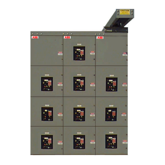
- Page 1 IB3.1.4.7B 07-31-98 ABB Power T&D Company Inc. North America Distribution Systems Group Installation and Maintenance Instructions ™ K-Line Plus Low Voltage Switchgear...
- Page 3 I N S T R U C T I O N A L B O O K L E T K-Line Plus Low Voltage Switchgear ™ © ABB Power T&D Company Inc. 201 Hickman Drive Sanford, Florida 32771-8201 Phone 407/323-8220 • Fax 407/322-8934...
-
Page 6: Table Of Contents
T able of Contents ™ INTRODUCTION TO K-LINE PLUS PLACING SWITCHGEAR INTO SERVICE..45 VOLTAGE SWITCHGEAR ........ 1 .........45 AFETY RECAUTIONS ........1 .........46 ENERAL NSTRUCTIONS NERGIZING THE ........1 COPE OF NSTRUCTIONS STANDARD CONSTRUCTION......47 IMPORTANT SAFETY NOTES AND ..........47 TANDARD OLOR WARNINGS............ -
Page 8: Introduction To K-Line Plus
NSTRUCTIONS The instructions are general in nature. They cover requirements for installation, setup, checkout and maintenance as applied to ABB K- Line Plus Metal Enclosed Low Voltage Power Circuit Breaker Switchgear. These instructions do not attempt to cover all variations and combinations of equipment and installations. - Page 9 K - L i n e P l u s...
-
Page 10: Important Safety Notes And Warnings
K - L i n e P l u s Chapter Important safety notes and warnings Switchgear operation depends on proper handling, installation, and maintenance. Neglecting fundamental requirements may lead to personal injury, failure of the switchgear, and property damage. Safety as described in this instruction book involves two conditions: •... - Page 11 Should clarification or additional information be required, refer the matter to your ABB Power T&D Company sales office. When communicating with ABB regarding the product covered by this Instruction Book, always reference the ABB assigned Shop Order (S.O.) number or Circuit Breaker Serial Number.
-
Page 12: Receiving And Handling
If there is damage from improper handling, file a claim for damages at once with the carrier and notify ABB. Note: ABB standard shipments are "FOB factory." ABB is not responsible for damage, after delivery of the equipment to the carrier. ANDLING... -
Page 13: Storage
K - L i n e P l u s TORAGE Leave the equipment on the shipping base. Store all equipment indoors in a well-ventilated area. The storage building should have a well-drained paved floor. temperature should be above 60ºF. The air should be dry (50% maximum humidity). -
Page 14: Site Preparation
K - L i n e P l u s Chapter Site Preparation ENERAL Before installing, consult all drawings furnished for the particular order. The drawings show top and front views of the switchgear, primary and secondary connection diagrams, and Bills of Materials. Study these drawings and the following recommendations before preparing the site plan drawings. - Page 15 K - L i n e P l u s...
-
Page 16: Indoor/ Outdoor Installation
K - L i n e P l u s Chapter Indoor/ Outdoor Installation ENERAL Metal-enclosed switchgear ships in sections. Sections up to 96 inches ship on heavy timber bases or on optional throw away steel bases Unload the switchgear as close to the installation site as possible. Raise the switchgear with jacks and move on rollers with the shipping bases in place or with an overhead hoist and spreader bar. - Page 17 K - L i n e P l u s In many locations the best way of moving the switchgear is with jacks and rollers. Do not remove the shipping base . Move the unit near the site. Raise the unit by jacks placed under the front and rear corners. See Figure 1.
- Page 18 K - L i n e P l u s Raise the unit enough to position a roller under the shipping base. Repeat the operation at the other end. See Figure 2 Figure 2. Raise the unit enough to position a roller under the shipping base.
- Page 19 K - L i n e P l u s Figure 3. Position rails on rollers as shown for lateral moving. Figure 4, Carefully push the unit onto a third roller. Locate the units in their final position. Raise the units to clear the rollers and channels.
-
Page 20: Raising By Slings
K - L i n e P l u s AISING BY LINGS Attach the optional lifting plates to the 4 holes provided in the top of the units as shown in Figure 5. They provide a large hole at each end for attaching a sling and spreader bar assembly. -
Page 21: Removal Of Shipping Base
K - L i n e P l u s EMOVAL OF HIPPING Once the units are in their final place, remove the shipping bases. Open the switchgear doors. Remove the bolts holding the Secure all doors and panels before shipping bases to the switchgear. - Page 22 REAKER VERHEAD IFTING EVICE For ease of handling K-Line Plus circuit breakers, a traveling overhead lifting device is available. The front section of the switchgear provides support for the lifting device. The hoist travels the full width of the switchgear.
- Page 23 K - L i n e P l u s Loosen all rails for the overhead lift device. Mount the Locator Plates as shown in Figure 8. Note that the plates have 8 round bosses that mate with holes in the rails. Adjust the rails as required to loosely secure the locator plates in place with the 8 bosses in their mating holes.
- Page 24 K - L i n e P l u s Position Overhead Lift device on the tines of forklift. Figure 10. Position Overhead Lift Device on tines of fork lift. Align the rollers on the Overhead lift device with the rails on the frame. Adjust the upper rear wheel to minimize...
- Page 25 K - L i n e P l u s Push the Overhead lift device off the fork-lift onto the rails. Figure 12. Push the Overhead Lift Device onto the rails. Re-install the carriage stop bracket, the end plate, and the lifting eye. Figure 13.
-
Page 26: Circuit Breaker Overhead
K - L i n e P l u s PERATION OF THE IRCUIT REAKER VERHEAD IFTING EVICE Observe the following requirements when operating the circuit breaker lifting device. The wheels must be properly set on track. Do not depend upon the drum attachment to support full weight. Allow 4-5 wraps of wire rope to remain on the drum. -
Page 27: Connections
K - L i n e P l u s ONNECTIONS WARNING Before making primary source connections verify that the primary cables are de-energized. Unit substations ship in separate sections. Each transformer is a separate section. The factory splits the buses for shipment. Secondary and control wiring end at terminal blocks located at the shipping split. - Page 28 K - L i n e P l u s Complete all internal connections. Make the external connections to control power sources and circuits, to secondary and potential circuits, to feeders, power sources and to ground. After completing all connections to secondary (control) circuits, follow these circuits and remove temporary connections from current transformer secondaries.
-
Page 29: Between Groups
K - L i n e P l u s ECONDARY AND ONTROL ONNECTIONS The factory wires the secondary and control connections using the connection diagram. The outgoing secondary and control connections terminate at terminal blocks. The terminal blocks for customer connections are accessible from the control conduit area. - Page 30 K - L i n e P l u s Torque the ½ inch bus hardware to 30-45 foot-pounds.
-
Page 31: Outdoor Installation
K - L i n e P l u s Outdoor Installation ENERAL Outdoor and indoor installations are similar. Outdoor units are on permanent bases. Use jacks to raise the units for positioning the rollers. The bases have lifting holes in each end for over head lifts. See Figure 20 on page 32. -
Page 32: Joining The Shipping Splits
K - L i n e P l u s OINING THE SHIPPING SPLITS For installations of more than three shipping splits, carefully locate the center section in its final position and add the remaining units on either end. Locate the shipping splits together in their final location relative to the floor anchor arrangement if used. - Page 33 K - L i n e P l u s Figure 14. Install gasket material between shipping splits before bolting together. Figure 15. Bolt shipping splits together.
- Page 34 K - L i n e P l u s Figure 16. Install gasket material between shipping splits. Figure 17. Loosely install the shipping split angle as shown.
- Page 35 K - L i n e P l u s Figure 18. Tighten the shipping split angle evenly. Apply sealant all around Figure 19. Install roof end caps as shown.
- Page 37 K - L i n e P l u s Lifting eye Anchor Plate Figure 20. Lifting eyes with anchor plates.
-
Page 38: Transformer Transitionu
Once positioned, make the connections and loosely re-assemble the slotted panels. Adjust the panels for best fit and secure the hardware. Figure 21. Outdoor K-Line Plus with transformer transition unit. - Page 39 K - L i n e P l u s...
-
Page 40: Testing And Final Inspection
K - L i n e P l u s Chapter Testing and Final Inspection ESTING DANGER Disconnect the primary power source during testing. Do not exceed the listed voltages for the voltage class of the equipment under test. Disconnect the shunt-connected coils such as potential transformers. Do not test solid state sensors or relays with high voltage. - Page 41 K - L i n e P l u s 60 HZ, RMS WITHSTAND VOLTAGES (PRIMARY CIRCUITS) WITHSTAND (1 MINUTE) Rated Voltage Factory Test Field Test Field Test 240v, 480v, 600v 2200 volts 1650 volts 2300 volts The Column headed DC WITHSTAND is a reference for those using dc tests to verify the integrity of connected switchgear.
-
Page 42: Control Circuit Checkout
K - L i n e P l u s ONTROL IRCUIT HECKOUT DANGER The breaker or cutout device of the local control power circuit must remain open when using a separate control power source. The preferred method to check the control circuit is to furnish a separate temporary source of control power of the required control voltage rating. - Page 43 K - L i n e P l u s Rack the remaining circuit breakers into the TEST position, one at a time. Test all electrically and manually operated breakers for closing and tripping, while they are in the TEST position. Use the optional test set available with the trip unit for testing solid state tripping.
- Page 44 K - L i n e P l u s To open the short circuiting device : Make sure that the current transformer secondary circuits are complete. Do not open circuit the secondary of an energized breaker. ¬ a) Single Ratio - Remove and store the shorting screw Do not remove the ground screw ¬...
- Page 45 K - L i n e P l u s INAL NSPECTION DANGER There are hazards of electrical shocks and/or burns whenever working in or around electrical equipment. Turn off power ahead of the switchgear before performing any maintenance operations. Check incoming line terminals to verify that the equipment is de-energized.
- Page 46 Typical K-Line Plus Composite Schematic (Electrically Operated) NOTES: This wiring diagram includes optional features not found on all K-Line Plus breakers, including an alarm switch, undervoltage trip device, LET/LEC, and spare auxiliary switch contacts. Secondary disconnect numbers begin with a letter that indicates in which plug the disconnect resides.
- Page 47 K - L i n e P l u s...
-
Page 48: Placing Switchgear Into Service
K - L i n e P l u s Chapter Placing Switchgear into Service AFETY RECAUTIONS DANGER There are hazards of electrical shocks and/or burns whenever working in or around electrical equipment. Turn off power ahead of the switchgear before performing any maintenance operations. -
Page 49: Energizing The Main Bus
K - L i n e P l u s NERGIZING THE After completing the control circuit checkout, energize the switchgear main bus. Energize the incoming bus to the switchgear main circuit breaker. Observe if operation of instruments and relays are correct. Energize the separate control power source, if furnished. -
Page 50: Standard Construction
K - L i n e P l u s Chapter Standard Construction TANDARD OLOR The standard paint color is ANSI #61. This finish is electro-static powder paint applied over an iron phosphate coating. This process achieves a smooth, uniform paint finish that conforms to all UL requirements. -
Page 51: Secondary Disconnectingd
K - L i n e P l u s ECONDARY ISCONNECTING EVICES Circuit breakers have self aligning disconnects sized for the required current. They make contact in the CONNECTED and TEST position, without the need for a test jumper. Figure 23. -
Page 52: Circuit Breakers
K - L i n e P l u s IRCUIT REAKERS Circuit breakers ship separately. The factory installs blocks in the movable parts of breakers with under-voltage release. On each switchgear all circuit breakers of like rating are interchangeable unless the secondary (control) circuit requires otherwise. - Page 53 K - L i n e P l u s...
-
Page 54: Maintenance
K - L i n e P l u s Chapter Maintenance ENERAL Inspect all switchgear installations at frequent intervals. Perform a visual inspection, front, and rear, to see that there is no evidence of loose parts, warping, or undue vibration. Take steps to remedy any deficiencies of this nature that may appear. -
Page 55: Semi -Annual Inspection
K - L i n e P l u s NNUAL NSPECTION At least twice yearly, perform a thorough inspection of the switchgear. Emphasize the following checks: Perform an overall visual inspection. Check all indicators, meters, and instruments for proper operation. Make sure all bolted panels are secure. -
Page 56: Annual Inspection
K - L i n e P l u s NNUAL NSPECTION Bolted connections should be tight. Discoloration, excessive corrosion, embrittled or discolored insulation may indicate an overheated connection. If found, follow the procedure described under the section “ Suspect Joint Maintenance." Inspect all cables for tight connections and ample support. -
Page 57: To 36 Month Inspection
K - L i n e P l u s 36 M ONTH NSPECTION Perform the following at 18 to 36 month intervals or sooner if required by local conditions or regulations. Clean the circuit breaker stationary primary contacts. IB6.2.11.1-1A, “ Installation/Maintenance Instructions for Low Voltage Power Circuit Breakers."... -
Page 58: Suspect Joint Maintenance
K - L i n e P l u s USPECT OINT AINTENANCE Open joint and inspect connection surfaces. Clean surfaces with an OSHA approved solvent. Dress contact surfaces that show minor corrosion or pitting by lightly rubbing with a polishing cloth such as “ 3M Scotch Brite." Take care to minimize the removal of plating. -
Page 59: Renewal Parts
Bill of Material before using touch up paint . The standard paint color is ANSI 61, light gray. A 12 ounce aerosol can of ANSI 61 touch-up paint is available from ABB under part number 887878A00. -
Page 60: Disclaimer Of Warranties And Limitation Of Liability
In no event will ABB be responsible to the user in contract, in tort (including negligence), strict liability or otherwise for any special,... - Page 61 K - L I N E P L U S...
- Page 62 K - L I N E P L U S Index ........49 ILTERS NSPECTIONS semi-annual........48 ........1, 3 NSTALLATION clearances ........7 ........52 ILL OF ATERIAL conduits ..........7 foundation.........7 ground ........21, 44 Supports .........43 ......24 LANGE ..........9 ACKS ..........21 UMPERS ........1, 42 HECKOUT ......45 IRCUIT...
- Page 63 K - L I N E P L U S ..........3, 4 ..........33 AFETY ESTING ....44 ......20, 51 ECONDARY ISCONNECTS ORQUE ALUES ..........1 ..31 ETUP RANSFORMER RANSITION HIPPING ASES removal ..........14 steel..........9 ......24 EATHERPROOFING wood..........9 drawings ...........7 ..........13 LINGS ..........6 TORAGE...
- Page 64 K - L I N E P L U S...
- Page 65 K - L I N E P L U S ABB Power T&D Company Inc. North American Distribution Systems Group 201 Hickman Drive Sanford, FL 32771-8201 Phone 407/323-8220 Fax 407/322-4434...