Table of Contents
Advertisement
Quick Links
Medium voltage products
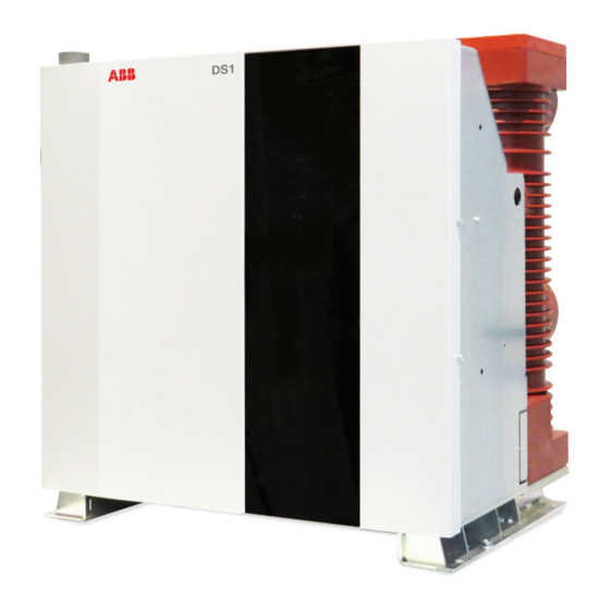
DS1
Technical Guideline for Installation and User Manual
3
4
4
4
4
5
5
6
6
7
7
8
8
8
10
10
11
12
12
12
12
13
13
14
14
14
16
16
16
17
17
18
18
18
18
19
19
19
20
20
20
20
21
21
22
23
23
23
24
24
24
25
25
26
28
28
28
28
28
28
29
29
29
30
31
31
31
Advertisement
Table of Contents

Related Manuals for ABB DS1


Summary of Contents for ABB DS1
-
Page 1: Table Of Contents
8.8 Spare parts and accessories 5.6 Preliminary operations Annex A - Terminal Block for auxiliary control circuit 6. Fixed Apparatus power circuit connections Annex B - External drawing for DS1 Integration 6.1 General directions B.1 Overall dimensions B.2 Internal connections 6.2 Mounting the connections... -
Page 3: Safety
When a DS1 is installed in a system, the To ensure that the installation conforms to the rules of good safety functions must be provided by working practice and safety in the workplace, make sure that system integration. -
Page 4: Introduction
If damage or discrepancies are discovered when the apparatus switches are designed for different installation configurations. is unpacked, notify ABB (directly or through the agent or For this reason, the information given below does not always supplier) as soon as possible and in any case within five days cover special configurations. -
Page 5: Storage
The apparatus must not be handled by inserting lifting devices directly under it. If this method is unavoidable, place the apparatus on a sturdy supporting surface (see fig. 2). Figure 2. Hooks and lifting holes for DS1 Figure 3. DS1 carrying method... -
Page 6: End Of Life Of Product
1.6 End of life of product ABB complies with the relevant laws and other environmental protection requirements in accordance with standard ISO 14 001. The duty of companies is to facilitate subsequent recycling or disposal at the end of product life. Always act in accordance with the local laws in force when disposing of the product. -
Page 7: Product Description
2. Product Description 2.1 General features DS1 are dry air insulated special purpose capacitor switches for indoor installation. Please refer to the corresponding technical not included non incluso catalogue code (1VCF000580) for the electrical performance data. For special installation conditions, please contact ABB. Please... -
Page 8: Reference Standards
2.2 Reference Standards Since it is a special purpose capacitor switch based on diodes for switching, DS1 is unable to break and make a fault The DS1 series apparatus complies with the following current. It can switch up to its rated current, indicated above. - Page 9 Please note that if unlikely circumstances occurs (temperature variation in the filling period in an uncontrolled environment. stage and tolerance of the pressure meter) when DS1 is operating at minimum temperature (-15 °C), the pressure could drop to a value able to trigger the warning level.
-
Page 10: Apparatus Operating Instructions
We reserve the right to make changes without notice in the course of technical development of the product. A specific real-time control completes the three-phase system. To load output side The system is fully integrated inside the DS1 and complete di- agnostics of the three-phase system application has been de- veloped. Note: The illustration is indi- cative and not binding. -
Page 11: Ds1 Closing And Opening Switching Behaviour
Typical DS1 switching behaviour is outlined below, where main circuit making and breaking possess the characteristics de- scribed above since DS1 contains the diode that naturally makes and breaks the current. Figure 8. DS1 behaviour during a power test at 17.5kV 630A... -
Page 12: Description Of The Control And Supply Electrical Interface
3.2 Description of the DS1 output DS1 provides the following 3 outputs, depending on the switch status: − Ready (dry contact closed when DS1 is ready to operate). − Watchdog (solid-state output blinks to indicate that DS1 is energized and processing its functions). -
Page 13: Description Of Ds1 Inputs
Homing − Open (DS1 is requested to perform an Open operation when DS1 only controls the position of the power part when this is, the switch is closed) within certain limits, in the Closed or Open Condition. A Hom- −... -
Page 14: Electrical Characteristics Of The Input
ABB’s service technician can detect any misuse of the In addition to its main function, DS1 is equipped with a pow- reset, homing and upstream CB functions. erful diagnostics able to identify internal faults (motor, control system, etc.) in the system before the operation. - Page 15 (only feasible in a de-energized condition) • Bad behaviour during actuations (can be adjusted by means of the commissioning procedure but only feasible in a de-energized condition and only by qualified ABB personnel) • Bad response to the Micro Motion self-check (can be ad-...
-
Page 16: Ds1 Diagnostics
Open condition). DS1 performs an operation by only applying an Open or DS1 implements an internal timer (default is 5 mins) that pre- Close command when the master system (system diagnos- vents closing after opening since the power capacitors are not tics) is in the READY condition. -
Page 17: Synchronization Diagnostics
Check pressure level. If it is not ok, plan a refill. a close operation. Check If it is ok and the Warning signal persists, contact 'Actions'. ABB and plan a check. DS1 can still perform a close and open operation. OPEN – – –... -
Page 18: Installation Guideline
MV Power Bus Bars. electrically located downstream with respect to them. DS1 is designed for a direct sense of rotation (R, S, T or A, Capacitor discharge B, C in time domain). Swap the S (or B) and T (or C) phases... -
Page 19: Installation Of Fixed Apparatus
Do not install the apparatus without providing a sound support on which to fix the DS1 base mainframe. Failure to do this can Clean the insulating parts with a clean dry rag and check that lead to serious malfunctions in the apparatus. -
Page 20: Fixed Apparatus Power Circuit Connections
Make sure that the connections do not exert force on the ter- minals. In the case of cable connections, carefully comply with the manufacturer’s instructions for terminating the cables. Figure 14. DS1 power connections Table of tightening torque Screw Tightening torque... -
Page 21: Three-Phase Power Line Connections
6.4 Three-phase power line connections The DS1 main connection layout can be summarized as fol- lows: Figure 15. DS1 main connection layout Connect six-power pole terminations high voltage bars substation. The three upper terminals are the input power connections while the three lower terminals are the output power connections (to capacitive load). -
Page 22: Synchronization Sensor
You are strongly advised to use ABB’s Keva sensor. This was the sensor used for testing DS1. If a different sensor is used, Install the voltage sensor with a clean layout in the compart- the voltage output must not exceed 1.2 Vpp. -
Page 23: Voltage Sensor Connections
6.8 Earthing Use the screw marked with the relative symbol to earth the fixed version of the apparatus. Clean and degrease an area about 30 mm in diameter all around. Cover the entire joint with vaseline after completing the Figure 19. Example of a metal duct to shield the assembly. -
Page 24: Commissioning
Auxiliary Control Make sure that the Normal switching and Note: DS1 is equipped with an event recorder. This means that Circuits connections to the control signaling circuits are correct. Supply ABB is always able to detect misuse of this function. -
Page 25: Pressure Monitoring
7.3 Pressure Monitoring 7.4 Interface summary for Maintenance and Commissioning The DS1 capacitor switch has pressurized poles with dry air at 3.7 bar relative nominal pressure (53.66 PSI) at approximately The BI/BO outlined below allow full management of DS1: 25 °C. -
Page 26: Commissioning - Test With No Power, No Sync
ABB S.p.A - Power Products Division Unità Operativa Sace-MV Once the wiring has been completed according to the DS1 The only connections that must remain are the two Power Sup- auxiliary circuit diagram, use of pushbuttons and all the inter- ply wires (Terminal boards 1 (+) and 2 (-)). - Page 27 Make sure that during fast actuation, DS1 is securely fixed to its support and that there are no significant vertical oscillations (otherwise, it means that the indications provided for position- ing and fixing the apparatus in the compartment have not been followed correctly).
-
Page 28: Periodical Inspections
The optimal time limits for carrying out the following operations can be set according DS1 is a pressurized switch filled with dry air. The factory fills to the results obtained during the periodic inspections. -
Page 29: Measurement Of Resistance Across Closed Contacts Of Poles
ABB service operators (at least Level 3). For an already installed apparatus that has performed 5,000 If DS1 reports a fault, identify the type of fault as described in operations or more, the resistance could increase up to fig. 12 and contact ABB. -
Page 30: Annex A - Terminal Block For Auxiliary Control Circuit
Annex A - Terminal Block for auxiliary control circuit Terminal connection functions -XDB Terminal board inside Figure 27. DS1 Terminal block for auxiliary control circuit ABB S.p.A - Power Products Division Unità Operativa Sace-MV... -
Page 31: Annex B - External Drawing For Ds1 Integration
Tipo / Type Frequency Version for Figure 28. External drawing for DS1 integration (dimensions in mm) B.2 Internal connections For the internal circuit diagram, refer to the official circuit dia- gram provided with the apparatus or ask for support from your... - Page 32 Petzower Strasse 8 D-40472 Ratingen D-14542 Glindow Phone: +49(0)2102/12-1230 Fax: +49(0)2102/12-1916 E-mail: powertech@de.abb.com www.abb.com The data and illustrations are not binding. We reserve the right to make modifications following technical developments to the product. © Copyright 2015 ABB. All rights reserved.