Huawei UPS5000-S Series Quick Manual
Hide thumbs
Also See for UPS5000-S Series:
- User manual (289 pages) ,
- Quick manual (16 pages) ,
- User manual (239 pages)
Table of Contents
Advertisement
Quick Links
UPS5000-S-(350 kVA-600 kVA)
Quick Guide
Issue: 08
Part Number: 31507820
Date: 2020-11-24
1
Overview
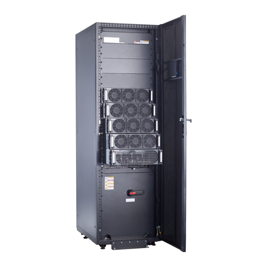
UPS5000-S-400K-SM/FM
(1) Power modules (2) Control module
(5) Bypass module (6) Mains input switch (7) Output switch
Copyright © Huawei Technologies Co., Ltd. 2020. All rights reserved.
UPS5000-S-500K-SM/FM
(3) Power distribution
module cover
1
(4) Maintenance bypass
switch
(8) Bypass input switch
Advertisement
Table of Contents

Related Manuals for Huawei UPS5000-S Series


Summary of Contents for Huawei UPS5000-S Series
- Page 1 UPS5000-S-(350 kVA-600 kVA) Quick Guide Issue: 08 Part Number: 31507820 Date: 2020-11-24 Copyright © Huawei Technologies Co., Ltd. 2020. All rights reserved. Overview UPS5000-S-500K-SM/FM UPS5000-S-400K-SM/FM (3) Power distribution (4) Maintenance bypass (1) Power modules (2) Control module module cover switch...
- Page 2 UPS5000-S-600K-SM/FM (1) Power modules (2) Control module (3) Power distribution module cover (4) Maintenance bypass switch (5) Bypass module (6) Mains input switch (7) Output switch (8) Bypass input switch Dimensions (H x W x D) UPS Model Weight UPS5000-S-400K-SM 670 kg UPS5000-S-400K-FM 710 kg...
-
Page 3: Installing The Ups
800 mm and secure the channel steel to the floor using expansion bolts. Huawei does not provide channel steel or expansion bolts used for securing channel steel. The customer should purchase channel steel (recommended width: 50 mm or more) and... - Page 4 UPS5000-S-400K/500K-SM/FM A: mounting holes on the channel steel B: mounting holes on the floor Unit: mm UPS5000-S-600K-SM/FM Securing the UPS Floor mounting: Use eight M12x60 expansion bolts to secure the cabinet to the ground. • Channel steel mounting: Use eight M12x60 common bolts to secure the cabinet to channel •...
-
Page 5: Connecting Cables
(1) Cabinet mounting holes (ground installation mode) (2) Cabinet mounting holes (channel steel installation mode) Installing the Front, Rear, Left, and Right Anchor Baffle Plates Connecting Cables 1. This document describes cable routing by removing the top cover when there are two mains inputs. -
Page 6: Ups Cable Connection Reference
UPS Cable Connection Reference • Prepare cables away from the cabinets to prevent scraps from falling inside. Cable scraps may ignite and cause personal injury or device damage. • After cables have been installed, clean the cabinets in a timely manner. Keep the cabinets and surrounding environment clean and tidy. - Page 7 Scenario 1: Routing Cables from the Top 1. Open the front door of the bypass cabinet, and 2. Remove the top cover from the remove front power distribution covers cabinet based on cable routes and (UPS5000-S-500K-FM is used as an example). dimensions.
- Page 8 4. Connect the ground cable to the UPS. UPS5000-S-600K-SM/FM 5. Connect mains input power cables. 6. Connect output power cables.
- Page 9 7. Connect bypass input power cables. 8. Connect battery cables. 9. Connect the signal cable. The figure shows the signal cable routing and is for reference only. Connect the cable based on the actual situation.
-
Page 10: Installation Verification
Scenario 2: Routing Cables from the Bottom 1. Remove the cable covers from the bottom of the cabinet, drill holes in the covers, attach grommet strips to the hole edges for protecting cables, and reinstall the cable covers. 2. Connect power cables and signal cables. For the screw specifications and torque used for connecting cables in a bottom cable routing scenario, refer to the top... -
Page 11: Powering On And Starting The Ups
2. After verifying the installation, reinstall all the covers. 3. (Remove the paper protective film from the sealing putty.) After routing cables and verifying cable connections, seal the gap between cables and the cabinet using sealing putty. Paper protective film Sealing putty Sealing putty must be used as a whole and the gap can be sealed only from the top. -
Page 12: Powering On The Ups
Close the upstream bypass and mains input switches. (Full configuration model) Close the UPS bypass input switch, output switch, and mains input switch. After the UPS is powered on, initialization begins. The MDU displays the Huawei logo and an initialization progress bar. Initial Startup If the UPS is powered on for the first time, you need to obtain the startup password from the •... - Page 13 2. Set the language, time, date, network parameters, and system parameters on the Settings Wizard screen. 3. After you perform the settings, the Bypass mode and No battery alarms are reported by the MDU and do not need to be cleared. If there is any other alarm, you need to rectify the fault.
-
Page 14: Shutting Down The Ups
System User LCD Preset Password WebUI Preset Password admin (system 000001 Changeme administrator) operator (common user) 000001 Changeme Powering On Loads 1. After the inverter starts, the UPS works in normal mode. The Bypass mode alarm disappears from the MDU. 2. - Page 15 Scan here for technical support (carrier): Huawei App Store Scan here for more documents: Support-E Support WeChat You can also log in to Huawei technical support website: https://support.huawei.com/enterprise https://support.huawei.com Huawei Technologies Co., Ltd. Huawei Industrial Base, Bantian, Longgang Shenzhen 518129 People's Republic of China...