Advertisement
Quick Links
Issue
04
Date
2020-12-30
HUAWEI TECHNOLOGIES CO., LTD.
No part of this document may be reproduced or transmitted in any form or by any means without prior
written consent of Huawei Technologies Co., Ltd.
and other Huawei trademarks are trademarks of Huawei Technologies Co., Ltd.
All other trademarks and trade names mentioned in this document are the property of their respective
holders.
The purchased products, services and features are stipulated by the contract made between Huawei and
the customer. All or part of the products, services and features described in this document may not be
within the purchase scope or the usage scope. Unless otherwise specified in the contract, all statements,
information, and recommendations in this document are provided "AS IS" without warranties, guarantees
or representations of any kind, either express or implied.
The information in this document is subject to change without notice. Every effort has been made in the
preparation of this document to ensure accuracy of the contents, but all statements, information, and
recommendations in this document do not constitute a warranty of any kind, express or implied.
Address:
Huawei Industrial Base
Bantian, Longgang
Shenzhen 518129
People's Republic of China
Website:
http://www.huawei.com
Email:
support@huawei.com
0
Advertisement

Related Manuals for Huawei OptiX RTN 320


Summary of Contents for Huawei OptiX RTN 320
- Page 1 Date 2020-12-30 The purchased products, services and features are stipulated by the contract made between Huawei and the customer. All or part of the products, services and features described in this document may not be within the purchase scope or the usage scope. Unless otherwise specified in the contract, all statements, information, and recommendations in this document are provided "AS IS"...
- Page 2 Anti-corrosion measures are required if an OAU 2A is installed in a location that is prone to corrosion. Contact • Test hoisting tools before use. the local Huawei office for details. A location is prone to corrosion if it is: • Avoid installation during extreme weather conditions, such as during thunderstorms, blizzards, or gales.
- Page 3 Safety Precautions DC power Do not leave any service cable unconnected •Do not install or remove a live power cable. Any contact between the power cable core and a conductor can generate Do not leave any service cable unconnected (see the following figure). electric arc or sparks, which may cause fire or eye injury.
- Page 4 Precautions for Local Maintenance When the OAU 2A is installed on a self-supporting tower, maintenance personnel cannot performance off-tower maintenance through WLAN, because the OAU 2A is installed at a high position. It is recommended that an outdoor network cable be added to connect the GE/NMS port. This network cable must be to a signal surge protector to enable local maintenance indoors. During local maintenance, you can connect a PC to the output end of the signal surge protector to access and maintain the NE using the Web LCT.
-
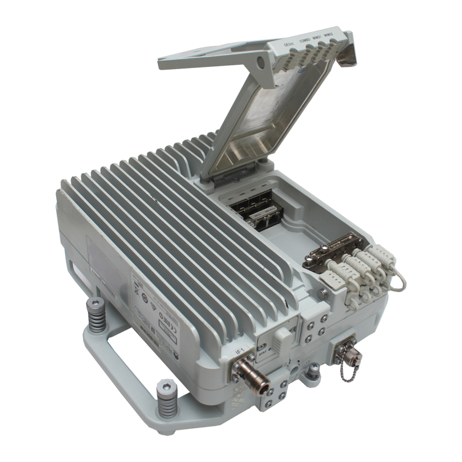
Page 5: Equipment Introduction
Equipment Introduction Equipment Components Appearance and ports Front view 102mm 210mm GE3(o) COMBO MIMO1 MIMO2 Screw of the maintenance compartment 290mm DC power GE1 (e) port • Do not keep the maintenance compartment open. NMS/GE2 (e) • Close the maintenance compartment after maintenance is complete. Ground screw Bottom view... - Page 6 Equipment Introduction Equipment Components Cables Stripping Length Indicator Ground cable Strip off the sheath of cables according to the stripping length indicator on one side of the OAU 2A to expose the shield layer. OT terminal Ground terminal • The ground terminal can be connected to a ground bar or U-shaped ground clip. Connect the ground terminal to whichever is the most appropriate for the scenario.
- Page 7 Terminating an Outdoor Network Cable with Shielded RJ45 Connectors Prepare the following tools. Insert the arranged core wires into an RJ45 connector according to the pin assignments and crimp the connector with the crimping tool. Crimp the RJ45 connector. RJ45 connector crimping tool Diagonal pliers Prepare an outdoor network cable and shielded RJ45 connectors.
- Page 8 Terminating Power Cables with a Tool-Less DC Power Connector Use a screwdriver to poke the cable locking latches out. Strip power cables based on the scale. Wires DC power cable Wires exposed 8 mm Insert the power cables. Ensure that the positive and negative cables are correctly connected. Positive and negative Red cable cables exposed...
- Page 9 Installing the OAU 2A Installation at a 1+0 Site Installation procedure Commissioning procedure For the method of installing an antenna, Install an OAU 2A on a wall or pole. follow the antenna installation guide Power on the OAU 2A. delivered with the antenna. •...
- Page 10 Installing the OAU 2A Installation at a 2+0 or 1+1 Site Installation procedure For the method of installing an antenna, Commissioning procedure follow the antenna installation guide Install an OAU 2A on a wall or pole. delivered with the antenna. Power on the OAU 2A.
- Page 11 Installing the OAU 2A Installation at an XPIC Site Installation procedure For the method of installing an antenna, Commissioning procedure follow the antenna installation guide Install an OAU 2A on a wall or pole. delivered with the antenna. Power on the OAU 2A. •...
- Page 12 Installing the OAU 2A Installation at an Intra-NE 2x2 MIMO Site Installation procedure Commissioning procedure Follow the antenna installation guide to install the antenna. Power on the OAU 2A. The vertical distance between two antennas must meet the requirements specified in the network plan.
- Page 13 Installing the OAU 2A Installation at a 4x4 MIMO Site Installation procedure Follow the antenna installation guide to install the antenna. Commissioning procedure Power on the OAU 2A. The vertical distance between two antennas must meet the requirements specified in the network plan.
-
Page 14: Installation Reference
Huawei has installed a conversion bracket on each OAU 2A before shipping it. Optional: Installing an OAU 2A on a Wall... - Page 15 Installation Reference Installing a Ground Cable Installing an IF Cable Ensure that the OT terminal is correctly installed. • Do not remove or insert an IF cable connector from or to the OAU 2A with power on. Otherwise, human injuries may be caused. •...
- Page 16 Installation Reference Installing a DC Power Cable and an Outdoor Network Cable Remove the rubber cable trough and waterproof block of the PWR cable hole. Loosen the screw on the desired cable clip at the second layer and remove the cable clip. Waterproof block PWR cable hole...
- Page 17 Installation Reference Installing an Outdoor Fiber or Cascade Fiber Closing the Maintenance Compartment Loosen the screw on the desired cable clip at the first layer and remove the cable clip. Lower the cover of the maintenance compartment. Remove the waterproof block in the cable hole of the GE3(o), COMBO, MIMO1, or MIMO2 port. GE3(o) waterproof block GE3(o) Check whether cable holes and waterproof blocks meet requirements.
- Page 18 Installation Reference Installing a Signal Lightning Surge Protector When a device uses SFP GE electrical modules, it must be used with a signal lightning surge protector. Connect the outdoor network cables to the signal lightning surge protector. Signal lightning Connect the surge end of the protector to GE electrical signals and use SFP GE electrical modules to surge protector connect the protect end to the device.
- Page 19 Installation Reference Selecting ground points Select ground points for the outdoor network cable. Select ground points for the DC cable. Ground the outdoor network cable at the following positions: Ground the DC cable at the following positions: 1. About 0.5 m to 1 m away from the port 1.
- Page 20 Installation Reference Selecting ground points Select ground points for the IF cable. Ground the IF cable at the following positions: 1. (Optional) Middle of the cable on the tower if the cable section on the tower is longer than 60 m 2.
- Page 21 Installation Reference Installing the Outdoor Optical Splitter Loosen the reinforce screws. Open the case cover. Optional: wall-mounting 4 mm hex key Cable distribution area Use a scribe template to determine the positions of mounting holes. Scribe pen Level Fiber routing clips Fiber fixing holes...
- Page 22 Installation Reference Installing the Outdoor Optical Splitter Optional: pole-mounting Install the pole assembly on the pole. Fix the case on the pole assembly and tighten the lower hold hoop. Loosen the screw on the hold hoop. Install the pole assembly on the pole. Complete installation of the pole assembly.
- Page 23 Installation Reference Installing the Outdoor Optical Splitter Guide the lead nylon of outdoor fibers through fiber Remove dustproof caps and insert fiber connectors into appropriate adapters fixing holes, fix the lead nylon and cut off redundant according to labels. part. Port in Fiber Interconne Description...
- Page 24 Installation Reference Laying out Cables General requirements Requirements for laying out cables outdoors 1. Bend radius • Route cables along the planned path, use outdoor cable ties or feeder clamps to bind cables properly and neatly at For power and PGND cables, ensure a bend radius of at least three times the cable diameter. intervals of about 1 meter, and cut off the excess of each cable tie without leaving sharp edges (ensuring a slack of about 5 2.
- Page 25 Appendix Waterproofing the IF Ports and Ground Cables of IF Cables and Outdoor Network Cables Powering On the OAU 2A Supplied with DC Power 1. Wrap one layer of PVC tape around the exposed part of a flexible waveguide or a group clip. 2.
- Page 26 Appendix Loading NE Data by Using the Web LCT The OAU 2A can connect to the Web LCT through its NMS port using a network cable or communicate with the Web LCT through its WLAN module. Maintenance compartment GE2(e) port USB port Connect the Web LCT to compartment...
-
Page 27: Checking The Installation
Appendix Checking the Installation Introduction of the Alignment Scope Components Check Item Verify that OAU 2As are installed in planned locations, and sufficient space is reserved for maintenance. Eye lens tube Locking ring Verify that OAU 2As are securely installed by turning them gently (in both the horizontal and vertical directions). - Page 28 Appendix Installing an Alignment Scope Remove the rubber plugs from the screw Install support rod A on the antenna mounting bracket. Secure the alignment scope to the support rod. holes reserved for installing the alignment scope on the antenna mounting bracket. Handwheel Rubber plug Captive...
- Page 29 Appendix Installing an Alignment Scope Remove the alignment scope and support robs and place them into the tool box in order. 58/59 >>...