
Related Manuals for ABB MNS-SG


Summary of Contents for ABB MNS-SG
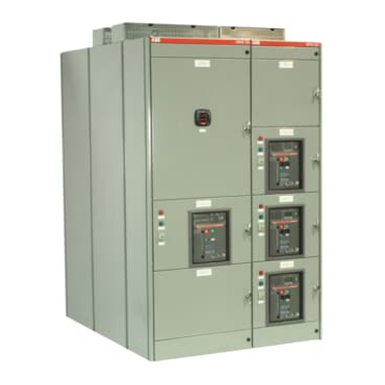
- Page 1 — ABB DISTRIBUTION SOLUTIONS Operation and Maintenance Manual MNS-SG Low Voltage Metal-Enclosed Drawout Switchgear...
- Page 2 2 MNS-SG Operation and Maintenance | Manual...
-
Page 3: Table Of Contents
9. Disclaimer of warranties and limitation of liability ..47 4.1. Installation location requirements ......25 4.2. Installation guidelines ..........26 4.3. Section installation sequence ......... 26 4.4. Install and connect shipping splits ......26 Manual | MNS-SG Operation and Maintenance 3... -
Page 4: Important User Information
— Important user information Follow your company’s safety procedures. ABB shall not assume any liability for any of the following: Do not remove covers, open doors or work on equipment Negligent handling of the MNS-SG (Switchgear) system. unless power has been turned off and all circuits de- Insufficient maintenance or non-compliance with the energized. - Page 5 Safety notations alert personnel to possible death, injury, or property damage situations. The following four safety recommended by ABB, must satisfy himself or herself notations and words are used in the manual to indicate the thoroughly that neither personal safety nor equipment degree of hazard that may be encountered by the user.
-
Page 6: General Information And System Description
Each section may contain a system of vertical bus, rated 1,600A up to 5,000A. The vertical bus is located in The MNS-SG switchgear consists of one or more vertical the busbar compartment, segregated from the device metal cabinets referred to as “sections.” Each section includes three separate compartments: device, busbar and compartment. -
Page 7: Technical Data Table
Up to 100kA @ 600V Standard - textured ANSI 61 Paint finish Enclosure Special colors available) * TTA: Switchgear assembly corresponding to the original type or system of switchgear assembly type tested in accordance with these standards. Manual | MNS-SG Operation and Maintenance 7... -
Page 8: Mns-Sg Standard Configuration
Device compartment: Composed of up to four vertical locations that house the installed devices, which are the main Base channels Bottom horizontal functional elements of the switchgear. Lateral segregation barrier / Wireway door Compartment barrier 8 MNS-SG Operation and Maintenance | Manual... -
Page 9: Busbar Compartments
Tie Bus Bar Tie Bus Bar PHASE C NEUTRAL Location CD PHASE A Cable Compartment Main Bus Bar PHASE B Main Bus Bar Bus Bar Compartment PHASE C Device Compartment MNS-SG standard compartments Bus Phases Manual | MNS-SG Operation and Maintenance 9... -
Page 10: Horizontal Neutral Bus (Optional Feature)
NEC 250-94, or by bonding the ground bus to the raceway 4,000A set 5,000A set enclosing the main supply conductors according to NEC 250- MBB (¼”x5”) MBB (¼”x5”) 92(B). Bus ratings and sizes 10 MNS-SG Operation and Maintenance | Manual... -
Page 11: Vertical Distribution Busbar
Each section is sequentially numbered as the general arrangement drawings are prepared. The left-most section is usually section 1, the next section to the right is 2, etc. This numbering scheme ensures the correct sequencing of vertical sections during installation. Manual | MNS-SG Operation and Maintenance 11... -
Page 12: Wireways
Bottom horizontal wireway 1.9.2. Top horizontal wireway The MNS-SG has a 3.9 in (100 mm) high, 17.7 in (450 mm) deep top-horizontal wireway. This wireway provides the space for interconnection wiring. It is covered by a steel door secured by two quarter-turn latch. -
Page 13: Vertical Wireway
2.0 mm thickness. channels are required in cold roll steel without painting or plating. This frame allow to have the structure welded when is installed. Reinforcements added for seismic structure Basic sub-frame for seismic structure Manual | MNS-SG Operation and Maintenance 13... -
Page 14: Exhaust Plenum (Optional)
! WARNING Following an arc flash, the equipment must be inspected by a qualified service technician prior to putting the switchgear back in service. Contact your local ABB representative for assistance. Temporary Cover Wall-opening dimensions After installing the plenum, reseal the gap according to NEC and local regulations. -
Page 15: Install Side-Exhaust Plenum
7. Once the extension connection is in place, attach additional extensions as needed to create the needed plenum length. Connect each extension using 14 M61 x 16 bolts, washers and nuts. Torque to 3.5 ft/lbs (4.7 Nm). Manual | MNS-SG Operation and Maintenance 15... -
Page 16: Install Rear-Exhaust Plenum
Install top covers 4. Connect each top cover to the adjacent cover with 10 M61 x 16 bolts, using the supplied washer and nuts for each bolt. Torque to 3.5 ft/lbs (4.7 Nm). 16 MNS-SG Operation and Maintenance | Manual... - Page 17 NOTE: For 31.5 in (800 mm) or 39.4 in (1,000 mm) wide Top Cover sections, install a rear-plenum transition to compensate for the width difference to the rear extension. End Cover End flaps Manual | MNS-SG Operation and Maintenance 17...
-
Page 18: Seismic Installation For Plenum
2.3. Seismic installation for plenum When the MNS-SG is arc resistant with plenum and rated for seismic, the seismic supports (not included by ABB) for the plenum installation must to be placed after the plenum extending at least 9 in (225 mm) minimum and maximum 40 in (1000 mm) from the side/back of the switchgear (see image). -
Page 19: Packaging And Handling
(2107 mm x 2000 mm x 2576 mm) for 1852 mm depth 90 in x 79 in x 101 in (2307 mm x 2000 mm x 2576 mm) for 2052 mm depth Shipping pallet dimensions Approximate values for weights per cubicle Manual | MNS-SG Operation and Maintenance 19... -
Page 20: Section Weight
63.1 lbs (28.6 kg) 200 kg 73.3 lbs (33.25 kg) 661 lbs Close coupling or bus duct raisers (5000A) 83.8 lbs (38 kg) 300 kg 94.1 lbs (42.7 kg) 114.6 lbs (52 kg) 20 MNS-SG Operation and Maintenance | Manual... -
Page 21: Receiving
See Temporary Storage. NOTE: Never set the switchgear sections on edge. To prevent deformation, sections should always rest flat on the floor or supporting structure. Manual | MNS-SG Operation and Maintenance 21... -
Page 22: Loading And Transport
3 mm. Wooden Crossbeam Transport with a hand-pulled truck Fork-lift transport Transport frame (wooden beam 10 x 12 cm) Roller transport Crane transport, transport unit in box 22 MNS-SG Operation and Maintenance | Manual... -
Page 23: Transport By Crane
Do not put the switchgear down on one edge, because of The lifting angles may be removed after the switchgear the danger of considerable mechanical damage. has been erected. Manual | MNS-SG Operation and Maintenance 23... -
Page 24: Temporary Storage
Check once per week for condensation on the components. If condensation is detected, dry the equipment and move it to a different storage area. 24 MNS-SG Operation and Maintenance | Manual... -
Page 25: Locate And Connect The Switchgear
Shipping split connection hardware 2. Make a final check that all components are in good condition. If there is any evidence of damage to the equipment, contact an ABB representative to evaluate the condition of the equipment before proceeding with installation. -
Page 26: Installation Guidelines
4.4. Install and connect shipping splits NOTE: Diagrams showing the location of fasteners and the appropriate torque values can be found in the Torque Table section of this manual. Frame connection using spacer bolts 26 MNS-SG Operation and Maintenance | Manual... -
Page 27: Splice Horizontal Busbars
Follow the next steps to connect the Main Bus Bar: Phase B and C Remove the Cable support if provided. Slide to the left b) If the Main Bus is insulated you must remove the insulation boots. Splice Links locations Manual | MNS-SG Operation and Maintenance 27... - Page 28 Remove the rear cover (GPO3 or metal sheet) to access the Main Bus bar area. The maximum gap between the left and right busbar is 0.9 in +/- 0.1 (25 mm +/- 3) Copper bars and cover to be removed 28 MNS-SG Operation and Maintenance | Manual...
- Page 29 & the red spacers of GPO3 at the end of the Bus Bar, those pieces sometimes are installed additionally but they are not necessary. Cooper spacer 3/8” 3200-5000 Amp Splice Kit Manual | MNS-SG Operation and Maintenance 29...
-
Page 30: Splicing Ground Busbar
18mm socket with an integral right-hand side of each shipping section and may be universal joint, to easily access and tighten all of the bolts. loosened and bridged to the adjacent section. 30 MNS-SG Operation and Maintenance | Manual... -
Page 31: Attach Switchgear To The Floor
Although the driving mechanism allows for easy hand Bolted to floor channels. operation, the weight of the circuit breaker cannot accidentally move the mechanism. See the corresponding ABB drawing for detailed operating instructions. Manual | MNS-SG Operation and Maintenance 31... - Page 32 3. Adjust the rails as required to loosely secure the locator plates in place with the bosses in their mating holes. Align wheels Push the overhead lift device off the forklift onto the rails. Adjust the rails 32 MNS-SG Operation and Maintenance | Manual...
-
Page 33: Operating Overhead Lifting Device
Make the connections only after the switchgear is in place, leveled, anchored and the sections joined and spliced. Bring the conduit into the top of the incoming section. Manual | MNS-SG Operation and Maintenance 33... - Page 34 2 x 3/8" x 4" 1000 E6.2 breaker connection table Section Vertical runback Size of lug Number of lugs width coupling connector 1000 4 x 3/8" x 5" 4 x 3/8" x 5" 34 MNS-SG Operation and Maintenance | Manual...
- Page 35 Top and floor cable cutouts Manual | MNS-SG Operation and Maintenance 35...
-
Page 36: Direct Connections To Main Sections
The top and bottom horizontal wireway are dedicated to If an external control source is used, it should be stable and not control wires. The horizontal wireway enables running subject to variations. Consult your ABB representative for control wiring between sections. minimum VA requirements. Terminals for external control sources will usually be provided in the top or bottom wireway 4.9.3. -
Page 37: Prepare To Energize Switchgear
Push the flaps closed by hand or, if too high to reach, using a pole. Flaps in open position Push to close flaps End flaps End flaps in open position in closed position Flaps in closed position Manual | MNS-SG Operation and Maintenance 37... -
Page 38: Testing And Final Inspection
3. To check for damaged insulation, apply potential tests If an external control voltage is present, verify that it is to the primary bus. Potential tests should be conducted OFF. phase-to-phase and phase-to-ground. 38 MNS-SG Operation and Maintenance | Manual... - Page 39 On electrically operated circuit breakers, discharge the springs; and the motor- disconnect- switch should be in the OFF position. Manual | MNS-SG Operation and Maintenance 39...
-
Page 40: Energize The Switchgear
Observe if operation of relays and instruments is correct. If applicable, close feeders and tie circuit breakers. Verify that all door panel screws are tight. Rack all drawout-type circuit breakers to the CONNECTED position. 40 MNS-SG Operation and Maintenance | Manual... -
Page 41: Maintenance
However, if the breaker will be removed for an extended period of time, it is advisable to replace it with ABB offers a range of preventive maintenance services and another breaker or to temporarily cover the hole where it programs. -
Page 42: Inspect Busbars
Inspect the gearing of the overhead lifting device when used. Keep well lubricated. In very dirty or gritty conditions, use a dry lubricant. Follow the recommendations of any individual device instructions furnished for maintenance of the device. 42 MNS-SG Operation and Maintenance | Manual... -
Page 43: 18-To-36 Month Inspection
The National Fire Protection Association (NFPA 70E) flash protection marking requirement applies to personnel who install, maintain, or repair electrical systems. (1 Standard for Electrical Safety Requirements for Employee Workplaces.) Article 110.16 Flash Protection: Switchboards, Manual | MNS-SG Operation and Maintenance 43... -
Page 44: Additional Resources
The following torque tables apply to horizontal and vertical busbar screw connections, electrical component screw connections, terminal connections structural components of the MNS-SG system. NOTE: For equipment connections and mountings, see the manufacturers’ technical data sheets. 44 MNS-SG Operation and Maintenance | Manual... -
Page 45: Torque Table
GPO3 glastic-copper Exterior metal panels and enclosures Iron-iron M6 Self- Ground bar connections Iron-iron M12 Hexagon head screw and nut tapping Torque 60 Nm (44 ft/lbs) Insulators-iron Ground bars Insulators-copper Initial tightening torque values Manual | MNS-SG Operation and Maintenance 45... - Page 46 Self-tapping screw Torque 4.7 Nm (3.5 ft/lbs) Frame and enclosure fasteners torque Main busbar to insulation supports torque M12 Hexagon head screw full thread Torque 70 Nm (52 ft/lbs) Main busbar coper-to-coper torque 46 MNS-SG Operation and Maintenance | Manual...
-
Page 47: Disclaimer Of Warranties And Limitation Of Liability
In no event will ABB be responsible to the user in contract, in Any such contract states the entire obligation of seller. tort (including negligence), strict liability or otherwise for any... - Page 48 Houston, TX 77042 be held liable for indirect or consequential damages. Tel.: 1 713 587-8000 ©Copyright 2019 ABB Inc. All rights reserved Toll Free: 1 888 385-1221 — Canada ABB, Inc.