ABB RELION REF615R Technical Manual
Hide thumbs
Also See for RELION REF615R:
- Engineering manual (124 pages) ,
- Manual (66 pages) ,
- Installation manual (48 pages)
Table of Contents
Advertisement
Quick Links
Advertisement
Table of Contents

Related Manuals for ABB RELION REF615R


Summary of Contents for ABB RELION REF615R
- Page 1 — RELION® PROTECTION AND CONTROL REF615R Technical Manual...
- Page 3 Document ID: 1MRS240050-IB Issued: 2019-07-02 Revision: C Product version: 4.1 © Copyright 2019 ABB. All rights reserved...
- Page 4 Copyright This document and parts thereof must not be reproduced or copied without written permission from ABB, and the contents thereof must not be imparted to a third party, nor used for any unauthorized purpose. The software or hardware described in this document is furnished under a license and may be used, copied, or disclosed only in accordance with the terms of such license.
- Page 5 ABB is not liable for any such damages and/or losses.
- Page 6 (Low-voltage directive 2006/95/EC). This conformity is the result of tests conducted by ABB in accordance with the product standards EN 50263 and EN 60255-26 for the EMC directive, and with the product standards EN 60255-1 and EN 60255-27 for the low voltage directive.
-
Page 7: Table Of Contents
Table of contents Table of contents Section 1 Introduction................23 This manual.................... 23 Intended audience.................. 23 Product documentation................24 Product documentation set..............24 Document revision history..............24 Related documentation..............25 Symbols and conventions...............25 Symbols.....................25 Document conventions..............25 Functions, codes and symbols............26 Section 2 REF615R overview............. 31 Overview....................31 Product version history.............. - Page 8 Table of contents Monitored data...................62 LED indication control................63 Function block................... 63 Functionality..................63 Time synchronization................64 Functionality..................64 Parameter setting groups............... 65 Function block................... 65 Functionality..................65 Fault records FLTMSTA................. 67 Functionality ..................67 Settings....................68 Monitored data...................69 Nonvolatile memory................74 Binary input.....................75 Binary input filter time................ 75 Binary input inversion................
- Page 9 Table of contents Signals..................82 GOOSERCV_INTL function block............. 83 Function block................83 Functionality................. 83 Signals..................83 GOOSERCV_CMV function block............. 84 Function block................84 Functionality................. 84 Signals..................84 GOOSERCV_ENUM function block...........84 Function block................84 Functionality................. 85 Signals..................85 GOOSERCV_INT32 function block........... 85 Function block................85 Functionality.................
- Page 10 Table of contents Monitored data................95 Standard configurable logic blocks............96 OR function block................. 96 AND function block............... 96 XOR function block...............97 NOT function block............... 97 MAX3 function block..............98 MIN3 function block..............98 R_TRIG function block..............99 F_TRIG function block..............99 T_POS_XX function blocks............100 Local/remote control function block CONTROL......
- Page 11 Table of contents Settings..................126 Monitored data................129 Technical data................130 Three-phase non-directional long-time overcurrent protection 51LT....................131 Identification................131 Function block................131 Functionality................131 Operation principle..............131 Timer characteristics ..............133 Application.................. 134 Signals..................134 Settings..................135 Monitored data................136 Three-phase directional overcurrent protection 67/51P and 67/50P137 Identification................
- Page 12 Table of contents Identification................171 Function block................172 Functionality................172 Operation principle..............172 Directional ground-fault principles..........177 Measurement modes..............183 Timer characteristics..............184 Directional ground-fault characteristics........185 Application.................. 196 Signals..................198 Settings..................199 Monitored data................203 Technical data................204 Sensitive earth-fault protection 50SEF..........205 Identification................
- Page 13 Table of contents Application.................. 215 Signals..................216 Settings..................217 Monitored data................217 Technical data................217 Loss of phase 37................218 Identification................218 Function block................218 Functionality................218 Operation principle..............218 Application.................. 220 Signals..................220 Settings..................221 Monitored data................221 Technical data................222 Voltage protection.................222 Three-phase overvoltage protection 59...........222 Identification................
- Page 14 Table of contents Function block................238 Functionality................238 Operation principle..............238 Application.................. 239 Signals..................240 Settings..................240 Monitored data................241 Technical data................241 Negative-sequence overvoltage protection 47........ 242 Identification................242 Function block................242 Functionality................242 Operation principle..............242 Application.................. 244 Signals..................244 Settings..................245 Monitored data................245 Technical data................
- Page 15 Table of contents Load shedding and restoration 81LSH..........271 Identification................271 Function block................271 Functionality................271 Operation principle..............272 Application.................. 277 Signals..................280 Settings..................281 Monitored data................281 Technical data................282 Power protection...................282 Three phase directional power protection 32P........ 282 Identification................282 Function block................282 Functionality................
- Page 16 Table of contents Technical data................301 Differential protection................301 Numerical stabilized low impedance restricted earth-fault protection 87LOZREF..............301 Identification................301 Function block................301 Functionality................301 Operation principle..............302 Application.................. 306 Signals..................310 Settings..................310 Monitored data................311 Technical data................311 Section 5 Protection-related functions..........313 Three-phase inrush detector INR............313 Identification..................
- Page 17 Table of contents Application..................330 Signals.....................331 Settings....................332 Monitored data.................332 High impedance fault detection HIZ............332 Identification..................332 Function block ................332 Functionality..................333 Operation principle................333 Application..................335 Signals.....................336 Settings....................336 Monitored data.................337 Arc protection AFD................337 Identification..................337 Function block................. 337 Functionality..................
- Page 18 Table of contents Settings....................360 Monitored data.................361 Technical data................. 361 Current circuit supervision CCM............362 Identification..................362 Function block................. 362 Functionality..................362 Operation principle................362 Application..................365 Signals.....................369 Settings....................370 Monitored data.................370 Technical data................. 370 Fuse failure supervision 60..............370 Identification..................370 Function block................. 371 Functionality..................
- Page 19 Table of contents Signals..................393 Settings..................393 Monitored data................394 Technical data................395 Three-phase voltage VA, VB, VC............ 395 Identification................395 Function block................395 Signals..................396 Settings..................396 Monitored data................397 Technical data................397 Ground current IG................397 Identification................397 Function block................397 Signals..................398 Settings..................398 Monitored data................398 Technical data................
- Page 20 Table of contents Identification................405 Function block................405 Signals..................405 Settings..................406 Monitored data................406 Technical data................407 Single-phase power and energy measurement SP, SE....407 Identification................407 Function block................407 Signals..................408 Settings..................408 Monitored data................409 Technical data................411 Frequency f..................411 Identification................411 Function block................411 Signals..................412 Settings..................412 Monitored data................412...
- Page 21 Table of contents Voltage variation PQSS................ 420 Identification..................420 Function block................. 420 Functionality..................420 Operation principle................421 Phase mode setting..............421 Variation detection..............422 Variation validation..............424 Duration measurement............... 427 Three/single-phase selection variation examples.......428 Recorded data................. 430 Application..................433 Signals.....................435 Settings....................435 Monitored data.................436 Voltage unbalance PQVUB..............
- Page 22 Table of contents Protection signal definition............458 Zone coordination...............459 Master and slave scheme............459 Thermal overload blocking............460 Operation principle................460 Signal collection and delay logic..........461 Shot initiation................465 Shot pointer controller..............469 Reclose controller...............470 Sequence controller..............472 Protection coordination controller..........473 Circuit breaker controller............474 Counters..................
- Page 23 Table of contents Settings....................512 Monitored data.................513 Section 10 Recording functions............515 Disturbance recorder DFR..............515 Functionality..................515 Recorded analog inputs..............515 Triggering alternatives..............515 Length of recordings..............517 Sampling frequencies..............517 Uploading of recordings..............518 Deletion of recordings..............519 Storage mode................519 Pre-trigger and post-trigger data..........519 Operation modes................
- Page 24 Table of contents Signals..................535 Settings..................536 Minimum minute pulse timer 62CLD-2..........536 Identification................536 Function block................536 Functionality................536 Signals..................537 Settings..................537 Programmable buttons FKEY............... 537 Identification..................537 Function block................. 538 Functionality..................538 Operation principle................538 Signals.....................538 Move function block MV................540 Function block................. 540 Functionality..................
- Page 25 Table of contents Local generic control points LCNTRL........... 554 Identification..................554 Function block................. 554 Functionality..................555 Operation principle................555 Signals.....................556 Settings....................556 Set reset SR..................559 Identification..................559 Function block................. 559 Functionality..................559 Signals.....................560 Settings....................561 Time delay off TOF................561 Identification..................561 Function block.................
- Page 26 Table of contents Standard inverse-time characteristics for overvoltage protection608 User programmable inverse-time characteristics for overvoltage protection..............612 IDMT curve saturation of overvoltage protection......612 IDMT curves for undervoltage protection........613 Standard inverse-time characteristics for undervoltage protection..................613 User-programmable inverse-time characteristics for undervoltage protection.............. 616 IDMT curve saturation of undervoltage protection......616 Frequency measurement and protection..........
- Page 27 Table of contents Section 18 Glossary................653 REF615R Technical Manual...
-
Page 29: Section 1 Introduction
Section 1 1MRS240050-IB C Introduction Section 1 Introduction This manual The technical manual contains application and functionality descriptions and lists function blocks, logic diagrams, input and output signals, setting parameters and technical data sorted per function. The manual can be used as a technical reference during the engineering phase, installation and commissioning phase, and during normal service. -
Page 30: Product Documentation
The intended use of documents during the product life cycle 1.3.2 Document revision history Document revision/date Product version History A/2013-11-22 First release B/2016-10-24 Content updated to correspond to the product version C/2019-07-02 Content updated Download the latest documents from the ABB Web site http://www.abb.com/substationautomation. REF615R Technical Manual... -
Page 31: Related Documentation
Section 1 1MRS240050-IB C Introduction 1.3.3 Related documentation Product series- and product-specific manuals can be downloaded from the ABB Web site http://www.abb.com/substationautomation. Symbols and conventions 1.4.1 Symbols The electrical warning icon indicates the presence of a hazard which could result in electrical shock. -
Page 32: Functions, Codes And Symbols
Section 1 1MRS240050-IB C Introduction • Abbreviations and acronyms are spelled out in the glossary. The glossary also contains definitions of important terms. • Push button navigation in the LHMI menu structure is presented by using the push button icons. To navigate between the options, use •... - Page 33 Section 1 1MRS240050-IB C Introduction Function IEC 61850 IEC 60617 REF615R Non-directional earth-fault protection, high stage, instance 1 EFHPTOC1 Io>> (1) 50G-1 Non-directional earth-fault protection, high stage, instance 2 EFHPTOC2 Io>> (2) 50G-2 Non-directional earth-fault protection, high stage, instance 3 EFHPTOC3 Io>>...
- Page 34 Section 1 1MRS240050-IB C Introduction Function IEC 61850 IEC 60617 REF615R Load shedding and restoration, instance 2 LSHDPFRQ2 UFLS/R (2) 81LSH-2 Loss of phase, instance 1 PHPTUC1 3I< (1) 37-1 Control Circuit-breaker control, instance 1 CBXCBR1 I <-> O CB (1) 52-1 Auto-reclosing DARREC1...
- Page 35 Section 1 1MRS240050-IB C Introduction Function IEC 61850 IEC 60617 REF615R Time delay off (8 pcs), instance 2 TOFGAPC2 TOF (2) TOF-2 Time delay on (8 pcs), instance 1 TONGAPC1 TON (1) TON -1 Time delay on (8 pcs), instance 2 TONGAPC2 TON (2) TON -2...
-
Page 37: Section 2 Ref615R Overview
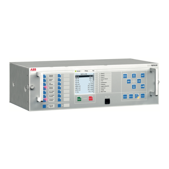
REF615R is a dedicated feeder protection relay designed for the protection, control, measurement and supervision of utility substations and industrial power systems. ® REF615R is a member of ABB's Relion product family. The REF615R protection relays are characterized by their versatility of 19" rack mounting and withdrawable design. -
Page 38: Pcm600 And Ied Connectivity Package Version
Protection and Control IED Manager PCM600 Ver.2.5 or later • REF615R Connectivity Package Ver.4.0 or later Download connectivity packages from the ABB Web site http://www.abb.com/substationautomation Local HMI The LHMI is used for setting, monitoring and controlling the protection relay. The LHMI comprises the display, buttons, LED indicators and communication port. -
Page 39: Leds
Section 2 1MRS240050-IB C REF615R overview Table 2: Large display Character size Rows in the view Characters per row Small, mono-spaced (6 × 12 pixels) The display view is divided into four basic areas. A070705-ANSI V3 EN Figure 4: Display layout 1 Header 2 Icon 3 Content... -
Page 40: Keypad
Section 2 1MRS240050-IB C REF615R overview 2.2.3 Keypad The LHMI keypad contains push buttons which are used to navigate in different views or menus. Using the push buttons, open or close commands can be given to objects in the primary circuit, for example, a circuit breaker, a contactor or a disconnector. The push buttons are also used to acknowledge alarms, reset indications, provide help and switch between local and remote control mode. -
Page 41: Programmable Push Buttons With Leds
Section 2 1MRS240050-IB C REF615R overview 2.2.4 Programmable push buttons with LEDs GUID-2210FFE5-7C08-4AA6-898A-5A39D3DDEAB3 V1 EN Figure 7: Programmable push buttons with LEDs The LHMI keypad on the left side of the protection relay contains 16 programmable push buttons with red LEDs. The buttons and LEDs are freely programmable, and they can be configured both for operation and acknowledgement purposes. -
Page 42: Web Hmi
Section 2 1MRS240050-IB C REF615R overview Web HMI The WHMI allows secure access to the protection relay via a Web browser. The supported Web browser versions are Internet Explorer 7.0, 8.0 and 9.0. WHMI is enabled by default. WHMI offers several functions. •... -
Page 43: Authorization
Section 2 1MRS240050-IB C REF615R overview Authorization The user categories have been predefined for the LHMI and the WHMI, each with different rights and default passwords. The default passwords can be changed with Administrator user rights. User authorization is disabled by default for LHMI but WHMI always uses authorization. - Page 44 Section 2 1MRS240050-IB C REF615R overview The protection relay utilizes Ethernet communication extensively for different purposes. The exact services depend on the ordered product variant and enabled functionality. The IEC 61850 communication implementation supports all monitoring and control functions. Additionally, parameter setting and DFR records can be accessed using the IEC 61850 protocol.
- Page 45 Section 2 1MRS240050-IB C REF615R overview GUID-ECEFAA08-402C-4154-B995-8255B0FE107F V1 EN Figure 9: Self-healing Ethernet ring solution The Ethernet ring solution supports the connection of up to thirty REF615R protection relays. If more than 30 protection relays are to be connected, it is recommended that the network is split into several rings with no more than 30 protection relays per ring.
-
Page 47: Section 3 Basic Functions
Section 3 1MRS240050-IB C Basic functions Section 3 Basic functions General parameters Table 4: Analog input settings, phase currents Parameter Values (Range) Unit Step Default Description Secondary current 1=0.2A 2=1A Rated secondary current 2=1A 3=5A Primary current 1.0...6000.0 100.0 Rated primary current Amplitude corr. - Page 48 Section 3 1MRS240050-IB C Basic functions Parameter Values (Range) Unit Step Default Description Amplitude corr. B 0.900...1.100 0.001 1.000 Phase B Voltage phasor magnitude correction of an external voltage transformer Amplitude corr. C 0.900...1.100 0.001 1.000 Phase C Voltage phasor magnitude correction of an external voltage transformer Voltage input type 1=Voltage trafo...
- Page 49 Section 3 1MRS240050-IB C Basic functions Parameter Values (Range) Unit Step Default Description Local engineer (4-8 Set password (4-8 chars) chars) Local admin (4-8 chars) Set password (4-8 chars) Remote viewer (9-20 Set password (9-20 chars) chars) Remote operator (9-20 Set password (9-20 chars) chars) Remote engineer (9-20...
- Page 50 Section 3 1MRS240050-IB C Basic functions Table 12: Ethernet rear port settings Parameter Values (Range) Unit Step Default Description IP address 192.168.2.10 IP address for rear port(s) Subnet mask 255.255.255.0 Subnet mask for rear port(s) Default gateway 192.168.2.1 Default gateway for rear port(s) Mac address XX-XX-XX-XX- Mac address for rear port(s)
- Page 51 Section 3 1MRS240050-IB C Basic functions Table 15: IEC 61850-8-1 MMS settings Parameter Values (Range) Unit Step Default Description Unit mode 1=Primary 0=Nominal IEC 61850-8-1 unit mode 0=Nominal 2=Primary-Nominal Table 16: Modbus settings Parameter Values (Range) Unit Step Default Description Serial port 1 0=Not in use 0=Not in use...
- Page 52 Section 3 1MRS240050-IB C Basic functions Parameter Values (Range) Unit Step Default Description CtlStructPWd1 **** Password for Modbus control struct 1 CtlStructPWd2 **** Password for Modbus control struct 2 CtlStructPWd3 **** Password for Modbus control struct 3 CtlStructPWd4 **** Password for Modbus control struct 4 CtlStructPWd5 **** Password for Modbus control struct 5...
- Page 53 Section 3 1MRS240050-IB C Basic functions Parameter Values (Range) Unit Step Default Description UR Class 1 Min events 0...999 Min number of class 1 events to generate UR UR Class 1 TO 0...65535 Max holding time for class 1 events to generate UR Class 2 Min events 0...999 Min number of class 2 events to generate UR...
- Page 54 Section 3 1MRS240050-IB C Basic functions Parameter Values (Range) Unit Step Default Description RTS delay 0...60000 RTS delay for COM1 Baudrate 1=300 6=9600 Baudrate for COM1 2=600 3=1200 4=2400 5=4800 6=9600 7=19200 8=38400 9=57600 10=115200 Parity 0=none 2=even Parity for COM1 1=odd 2=even If this protocol does not operate as expected, check that another serial...
- Page 55 Section 3 1MRS240050-IB C Basic functions Table 20: Time settings Parameter Values (Range) Unit Step Default Description Date Date Time Time Time format 1=24H:MM:SS:MS 1=24H:MM:SS:M Time format 2=12H:MM:SS:MS Date format 1=DD.MM.YYYY 1=DD.MM.YYYY Date format 2=DD/MM/YYYY 3=DD-MM-YYYY 4=MM.DD.YYYY 5=MM/DD/YYYY 6=YYYY-MM-DD 7=YYYY-DD-MM 8=YYYY/DD/MM Local time offset -840...840...
- Page 56 Section 3 1MRS240050-IB C Basic functions Table 21: Binary input signals in cards X110 and X130 Name Type Terminal Protection relay type Protection relays Protection relays with normal BO with high-speed contacts contacts IN1+ IN1+ X110-Input 1 BOOLEAN Common- Common- IN2+ IN2+ X110-Input 2...
-
Page 57: Self-Supervision
Section 3 1MRS240050-IB C Basic functions Table 23: Binary output signals in power supply module or card X110 Name Type Default Terminal number TRIP BOOLEAN 0=False 29, 30 OUT1 BOOLEAN 0=False 27, 28 OUT2 BOOLEAN 0=False 25, 26 OUT3 BOOLEAN 0=False 23, 24 OUT4... - Page 58 Figure 10: Output contact The internal fault code indicates the type of internal relay fault. When a fault appears, record the code so that it can be reported to ABB customer service. Table 25: Internal fault indications and codes Fault indication...
- Page 59 Section 3 1MRS240050-IB C Basic functions Fault indication Fault code Additional information Internal Fault Faulty Signal Output relay(s) in card SO-relay(s),X110 located in slot X110 Internal Fault Faulty Signal Output relay(s) in card SO-relay(s),X120 located in slot X120 Internal Fault Faulty Signal Output relay(s) in card SO-relay(s),X130 located in slot X130...
-
Page 60: Warnings
LHMI. The warning indication message can be manually cleared. If a warning appears, record the name and code so that it can be provided to ABB customer service. Table 26:... -
Page 61: Programmable Leds
Section 3 1MRS240050-IB C Basic functions Warning indication Warning code Additional information Warning Error in the SCL configuration file or the file SCL config error is missing Warning Too many connections in the configuration Logic error Warning Error in the SMT connections SMT logic error Warning Error in the GOOSE connections... -
Page 62: Function Block
Section 3 1MRS240050-IB C Basic functions 3.3.2 Function block GUID-00339108-34E4-496C-9142-5DC69F55EE7A V1 EN Figure 11: Function block 3.3.3 Functionality The programmable LEDs reside on the right side of the display on the LHMI. GUID-4B2A5FAE-18FD-4343-8069-20D4182E81E4 V1 EN Figure 12: Programmable LEDs on the right side of the ANSI LHMI display GUID-497C4732-55E5-483A-89AE-F8BACFE8DF36 V1 EN Figure 13: Programmable LEDs on the right side of the IEC LHMI display... - Page 63 Section 3 1MRS240050-IB C Basic functions The LED status also provides a means for resetting the individual LED via communication. The LED can also be reset from configuration with the RESET input. The red has the higher priority than the green. The control of the LEDs is part of the SMT functionality.
- Page 64 Section 3 1MRS240050-IB C Basic functions "Follow-S": Follow Signal, ON In this mode ALARM follows the input signal value, Non-latched. Activating signal GUID-952BD571-874A-4572-8710-F0E879678552 V1 EN Figure 16: Operating sequence "Follow-S" "Follow-F": Follow Signal, Flashing Similar to "Follow-S", but instead the LED is flashing when the input is active, Non- latched.
-
Page 65: Signals
Section 3 1MRS240050-IB C Basic functions Activating signal Acknow. GUID-1B1414BD-2535-40FA-9642-8FBA4D19BA4A V1 EN Figure 18: Operating sequence "LatchedAck-F-S" 3.3.4 Signals Table 27: LED Input signals Name Type Default Description BOOLEAN 0=False Ok input for LED 1 ALARM BOOLEAN 0=False Alarm input for LED 1 RESET BOOLEAN 0=False... -
Page 66: Settings
Section 3 1MRS240050-IB C Basic functions Name Type Default Description ALARM BOOLEAN 0=False Alarm input for LED 8 RESET BOOLEAN 0=False Reset input for LED 8 BOOLEAN 0=False Ok input for LED 9 ALARM BOOLEAN 0=False Alarm input for LED 9 RESET BOOLEAN 0=False... - Page 67 Section 3 1MRS240050-IB C Basic functions Parameter Values (Range) Unit Step Default Description Alarm mode 0=Follow-S 0=Follow-S Alarm mode for programmable LED 5 1=Follow-F 2=Latched-S 3=LatchedAck-F-S Description Programmable Programmable LED description LEDs LED 5 Alarm mode 0=Follow-S 0=Follow-S Alarm mode for programmable LED 6 1=Follow-F 2=Latched-S 3=LatchedAck-F-S...
-
Page 68: Monitored Data
Section 3 1MRS240050-IB C Basic functions 3.3.6 Monitored data Table 29: LED Monitored data Name Type Values (Range) Unit Description Programmable LED Enum 0=None Status of programmable LED 1=Ok 3=Alarm Programmable LED Enum 0=None Status of programmable LED 1=Ok 3=Alarm Programmable LED Enum 0=None... -
Page 69: Led Indication Control
Section 3 1MRS240050-IB C Basic functions LED indication control 3.4.1 Function block LEDPTRC OUT_START OUT_OPERATE OUT_ST_A OUT_OPR_A OUT_ST_B OUT_OPR_B OUT_ST_C OUT_OPR_C OUT_ST_NEUT OUT_OPR_NEUT GUID-7F172280-5ECA-4416-A841-5AE04B753C96 V1 EN Figure 19: Function block 3.4.2 Functionality The protection relay includes a global conditioning function LEDPTRC that is used with the protection indication LEDs. -
Page 70: Time Synchronization
Section 3 1MRS240050-IB C Basic functions Time synchronization 3.5.1 Functionality The protection relay has an internal real-time clock which can be either free-running or synchronized from an external source. The real-time clock is used for time stamping events, recorded data and disturbance recordings. The protection relay is provided with a 48 hour capacitor backup that enables the real-time clock to keep time in case of an auxiliary power failure. -
Page 71: Parameter Setting Groups
IRIG-B sync source is selected and the IRIG-B signal source is connected. ABB has tested the IRIG-B with the following clock masters. • Tekron TTM01 GPS clock with IRIG-B output •... - Page 72 Section 3 1MRS240050-IB C Basic functions Table 30: Optional operation modes for setting group selection SG operation mode Description Operator (Default) Setting group can be changed with the setting Settings/Setting group/Active group. Value of the SG_LOGIC_SEL output is FALSE. Logic mode 1 Setting group can be changed with binary inputs (BI_SG_2...BI_SG_6).
-
Page 73: Fault Records Fltmsta
Section 3 1MRS240050-IB C Basic functions Table 32: SG operation mode = “Logic mode 2” Input BI_SG_2 BI_SG_3 BI_SG_4 BI_SG_5 BI_SG_6 Active group FALSE FALSE FALSE TRUE FALSE FALSE TRUE FALSE TRUE FALSE FALSE TRUE TRUE FALSE TRUE TRUE The setting group 1 can be copied to any other or all groups from HMI (Copy group 1). Fault records FLTMSTA 3.7.1 Functionality... -
Page 74: Settings
Section 3 1MRS240050-IB C Basic functions The fault-related current, voltage, frequency, angle values, shot pointer and the active setting group number are taken from the moment of the operate event, or from the beginning of the fault if only a pickup event occurs during the fault. The maximum current value collects the maximum fault currents during the fault. -
Page 75: Monitored Data
Section 3 1MRS240050-IB C Basic functions 3.7.3 Monitored data Table 34: FR Monitored data Name Type Values (Range) Unit Description Fault number INT32 0...999999 Fault record number Time and date Timestamp Fault record time stamp Protection Enum 0=Unknown Protection function 1=PHLPTOC1 2=PHLPTOC2 6=PHHPTOC1... - Page 76 Section 3 1MRS240050-IB C Basic functions Name Type Values (Range) Unit Description 65=LSHDPFRQ 66=LSHDPFRQ 67=LSHDPFRQ 68=LSHDPFRQ 69=LSHDPFRQ 71=DPHLPDOC 72=DPHLPDOC 74=DPHHPDOC 77=MAPGAPC1 78=MAPGAPC2 79=MAPGAPC3 85=MNSPTOC1 86=MNSPTOC2 88=LOFLPTUC1 90=TR2PTDF1 91=LNPLDF1 92=LREFPNDF1 94=MPDIF1 96=HREFPDIF1 100=ROVPTOV 101=ROVPTOV 102=ROVPTOV 104=PHPTOV1 105=PHPTOV2 106=PHPTOV3 108=PHPTUV1 109=PHPTUV2 110=PHPTUV3 112=NSPTOV1 113=NSPTOV2 116=PSPTUV1...
- Page 77 Section 3 1MRS240050-IB C Basic functions Name Type Values (Range) Unit Description -93=SPHLPTOC -92=SPHLPTOC -89=SPHHPTOC -88=SPHHPTOC -86=SPHPTUV3 -85=SPHPTUV2 -84=SPHPTUV1 -82=SPHPTOV3 -81=SPHPTOV2 -80=SPHPTOV1 -25=OEPVPH4 -24=OEPVPH3 -23=OEPVPH2 -22=OEPVPH1 -19=PSPTOV2 -18=PSPTOV1 -15=PREVPTOC -12=PHPTUC2 -11=PHPTUC1 -9=PHIZ1 5=PHLTPTOC1 20=EFLPTOC4 26=EFHPTOC5 27=EFHPTOC6 37=NSPTOC3 38=NSPTOC4 45=T1PTTR2 54=DEFHPDEF 75=DPHHPDOC 89=LOFLPTUC2 103=ROVPTOV...
- Page 78 Section 3 1MRS240050-IB C Basic functions Name Type Values (Range) Unit Description Max diff current IC FLOAT32 0.000...80.000 Maximum phase C differential current Diff current IA FLOAT32 0.000...80.000 Differential current phase A Diff current IB FLOAT32 0.000...80.000 Differential current phase B Diff current IC FLOAT32 0.000...80.000...
- Page 79 Section 3 1MRS240050-IB C Basic functions Name Type Values (Range) Unit Description Max current IA3 FLOAT32 0.000...50.000 Maximum phase A current (c) Max current IB3 FLOAT32 0.000...50.000 Maximum phase B current (c) Max current IC3 FLOAT32 0.000...50.000 Maximum phase C current (c) Max current IG3 FLOAT32 0.000...50.000...
-
Page 80: Nonvolatile Memory
Section 3 1MRS240050-IB C Basic functions Name Type Values (Range) Unit Description PDNSPTOC1 rat. FLOAT32 0.00...999.99 46PD ratio I2/I1 I2/I1 Frequency FLOAT32 30.00...80.00 Frequency Frequency gradient FLOAT32 -10.00...10.00 Hz/s Frequency gradient Conductance Yo FLOAT32 -1000.00...1000. Conductance Yo Susceptance Yo FLOAT32 -1000.00...1000. -
Page 81: Binary Input
Section 3 1MRS240050-IB C Basic functions Binary input 3.9.1 Binary input filter time The filter time eliminates debounces and short disturbances on a binary input. The filter time is set for each binary input of the protection relay. GUID-13DA5833-D263-4E23-B666-CF38B1011A4B V1 EN Figure 21: Binary input filtering 3 Input signal... -
Page 82: Binary Input Inversion
Section 3 1MRS240050-IB C Basic functions 3.9.2 Binary input inversion The parameter Input # invert is used to invert a binary input. Table 36: Binary input states Control voltage Input # invert State of binary input FALSE (0) TRUE (1) TRUE (1) FALSE (0) When a binary input is inverted, the state of the input is TRUE (1) when no control voltage... -
Page 83: Trip Output Contacts
Section 3 1MRS240050-IB C Basic functions protection relay to external annunciation equipment for indicating, signalling and recording. All output contacts, except IRF output, are trip duty rated (Trip Output) and are designated as TRIP, OUT1, OUT2...OUT6. There are two types of these trip output contacts either marked as TO for normal binary output contacts or HSTO for high-speed output contacts. -
Page 84: Dual Single-Pole High-Speed Trip Outputs Hsto1, Hsto2 And Hsto3
Section 3 1MRS240050-IB C Basic functions OUT3 OUT3 OUT2 OUT2 OUT1 OUT1 TRIP GUID-3C9B8A53-7FC5-44E4-B80B-D309EA4D5CF1 V1 EN Figure 22: Typical connection of trip output contacts 3.10.1.2 Dual single-pole high-speed trip outputs HSTO1, HSTO2 and HSTO3 HSO1, HSO2 and HSO3 are dual parallel connected, single-pole, normally open/form A high-speed power outputs. -
Page 85: Internal Fault Signal Output Irf
Section 3 1MRS240050-IB C Basic functions HS TO OUT6 OUT6 HS TO OUT5 OUT5 HS TO OUT4 OUT4 GUID-0ACD4BE5-EF88-4A00-A8D8-5BFD9BA9AC81 V1 EN Figure 23: High-speed power outputs HSTO1, HSTO2 and HSTO3, when the protection relay is ordered with high-speed outputs The reset time of the high-speed output contacts is longer than that of the conventional output contacts. -
Page 86: Goose Function Blocks
Section 3 1MRS240050-IB C Basic functions 3.11 GOOSE function blocks GOOSE function blocks are used for connecting incoming GOOSE data to application. They support BOOLEAN, Dbpos, Enum, FLOAT32, INT8 and INT32 data types. Common signals The VALID output indicates the validity of received GOOSE data, which means in case of valid, that the GOOSE communication is working and received data quality bits (if configured) indicate good process data. -
Page 87: Goosercv_Dp Function Block
Section 3 1MRS240050-IB C Basic functions 3.11.2 GOOSERCV_DP function block 3.11.2.1 Function block GUID-63C0C3EE-1C0E-4F78-A06E-3E84F457FC98 V1 EN Figure 26: Function block 3.11.2.2 Functionality The GOOSERCV_DP function is used to connect the GOOSE double binary inputs to the application. 3.11.2.3 Signals Table 39: GOOSERCV_DP Output signals Name Type... -
Page 88: Signals
Section 3 1MRS240050-IB C Basic functions 3.11.3.3 Signals Table 40: GOOSERCV_MV Output signals Name Type Description FLOAT32 Output signal VALID BOOLEAN Output signal 3.11.4 GOOSERCV_INT8 function block 3.11.4.1 Function block GUID-B4E1495B-F797-4CFF-BD19-AF023EA2D3D9 V1 EN Figure 28: Function block 3.11.4.2 Functionality The GOOSERCV_INT8 function is used to connect the GOOSE 8 bit integer inputs to the application. -
Page 89: Goosercv_Intl Function Block
Section 3 1MRS240050-IB C Basic functions 3.11.5 GOOSERCV_INTL function block 3.11.5.1 Function block GUID-241A36E0-1BB9-4323-989F-39668A7B1DAC V1 EN Figure 29: Function block 3.11.5.2 Functionality The GOOSERCV_INTL function is used to connect the GOOSE double binary input to the application and extracting single binary position signals from the double binary position signal. -
Page 90: Goosercv_Cmv Function Block
Section 3 1MRS240050-IB C Basic functions 3.11.6 GOOSERCV_CMV function block 3.11.6.1 Function block GUID-4C3F3A1A-F5D1-42E1-840F-6106C58CB380 V1 EN Figure 30: Function block 3.11.6.2 Functionality The GOOSERCV_CMV function is used to connect GOOSE measured value inputs to the application. The MAG_IN (amplitude) and ANG_IN (angle) inputs are defined in the GOOSE configuration (PCM600). -
Page 91: Functionality
Section 3 1MRS240050-IB C Basic functions 3.11.7.2 Functionality The GOOSERCV_ENUM function block is used to connect GOOSE enumerator inputs to the application. 3.11.7.3 Signals Table 44: GOOSERCV_ENUM Output signals Name Type Description Enum Output signal VALID BOOLEAN Output signal 3.11.8 GOOSERCV_INT32 function block 3.11.8.1 Function block... -
Page 92: Type Conversion Function Blocks
Section 3 1MRS240050-IB C Basic functions 3.12 Type conversion function blocks 3.12.1 QTY_GOOD function block 3.12.1.1 Functionality The QTY_GOOD function block evaluates the quality bits of the input signal and passes it as a Boolean signal for the application. The IN input can be connected to any logic application signal (logic function output, binary input, application function output or received GOOSE signal). -
Page 93: Signals
Section 3 1MRS240050-IB C Basic functions The OUT output indicates quality bad of the input signal. Input signals that have any other than test bit set, will indicate quality bad status. 3.12.2.2 Signals Table 48: QTY_BAD Input signals Name Type Default Description Input signal... -
Page 94: T_F32_Int8 Function Block
Section 3 1MRS240050-IB C Basic functions 3.12.4 T_F32_INT8 function block 3.12.4.1 Functionality The T_F32_INT8 function is used to convert 32-bit floating type values to 8-bit integer type. The rounding operation is included. Output value saturates if the input value is below the minimum or above the maximum value. -
Page 95: Function Block
Section 3 1MRS240050-IB C Basic functions 3.13.1.2 Function block SHFT SHIFT HOLD RESET GUID-6C06C594-67A7-4CA0-ACED-0839B9C7D66B V1 EN Figure 34: Function block 3.13.1.3 Functionality The generic select shifter function SHFT turns off the present output and turns on the next consecutive enabled output for each positive edge of the shift input. The shifter output can be reset to the first output or held in place, if required. - Page 96 Section 3 1MRS240050-IB C Basic functions Shift selector When the function is first enabled, O1 is set to TRUE. Each rising edge of the SHIFT input turns the presently asserted output Ox (x = 1...8) to FALSE and turns the next higher enabled output to TRUE. Figure 36 shows a logic diagram with all outputs enabled.
- Page 97 Section 3 1MRS240050-IB C Basic functions SHIFT HOLD RESET GUID-A18C180E-664D-4DA1-9376-7D82D7204C8A V1 EN Figure 37: Logic diagram with O2, O7 and O8 disabled If the HOLD input is set to TRUE and the Hold mode setting is “Freeze”, rising edges on the SHIFT input are ignored and the present output is unchanged.
- Page 98 Section 3 1MRS240050-IB C Basic functions If the HOLD input is set to TRUE and the Hold mode setting is “Disable”, rising edges on the SHIFT input are ignored and all outputs are set to FALSE. When the HOLD input returns to FALSE, the original output that was TRUE when HOLD was activated returnes to TRUE unless the RESET input had been set TRUE or the Operation setting was set to “Off”.
-
Page 99: Application
Section 3 1MRS240050-IB C Basic functions SHIFT HOLD RESET GUID-6A48BE57-4BDC-4E68-B8EF-6560DC6CA3E2 V1 EN Figure 40: Logic diagram with RESET input 3.13.1.5 Application The shift selector function can be used in any application where it is desired to select among exclusive modes of operation using a momentary push-button as user input. In the example in Figure , the shifter outputs can be connected to the setting group inputs of the... -
Page 100: Signals
Section 3 1MRS240050-IB C Basic functions 3.13.1.6 Signals Table 52: SHFT input signals Name Type Default Description SHIFT BOOLEAN 0=False Shift Input HOLD BOOLEAN 0=False Hold present output RESET BOOLEAN 0=False Reset to output 1 Table 53: SHFT output signals Name Type Description... -
Page 101: Monitored Data
Section 3 1MRS240050-IB C Basic functions Parameter Values (Range) Unit Step Default Description Description SHFTGAPC1 Description of output 4 Status of Output 4 Enable 0=False 1=True Allow output 5 to be asserted 1=True Description SHFTGAPC1 Description of output 5 Status of Output 5 Enable 0=False 1=True... -
Page 102: Standard Configurable Logic Blocks
Section 3 1MRS240050-IB C Basic functions Name Type Values (Range) Unit Description BOOLEAN 0=False Status of output 7 1=True BOOLEAN 0=False Status of output 8 1=True ASSRTD_OUT INT32 1...8 Present output position 3.13.2 Standard configurable logic blocks 3.13.2.1 OR function block Functionality OR and OR6 are used to form general combinatory expressions with Boolean variables. -
Page 103: Xor Function Block
Section 3 1MRS240050-IB C Basic functions AND has two inputs and AND6 has six inputs. Function block GUID-7592F296-60B5-4414-8E17-2F641316CA43 V1 EN Figure 43: Function blocks Settings The function does not have any parameters available in LHMI or PCM600. 3.13.2.3 XOR function block Functionality The exclusive OR function XOR is used to generate combinatory expressions with Boolean variables. -
Page 104: Max3 Function Block
Section 3 1MRS240050-IB C Basic functions Function block GUID-0D0FC187-4224-433C-9664-908168EE3626 V1 EN Figure 45: Function block Settings The function does not have any parameters available in LHMI or PCM600. 3.13.2.5 MAX3 function block Functionality The maximum function MAX3 selects the maximum value from three analog values. The disconnected inputs have the value 0. -
Page 105: R_Trig Function Block
Section 3 1MRS240050-IB C Basic functions Function block GUID-40218B77-8A30-445A-977E-46CB8783490D V1 EN Figure 47: Function block Settings The function does not have any parameters available in LHMI or PCM600. 3.13.2.7 R_TRIG function block Functionality R_TRIG is used as a rising edge detector. R_TRIG detects the transition from FALSE to TRUE at the CLK input. -
Page 106: T_Pos_Xx Function Blocks
Section 3 1MRS240050-IB C Basic functions Function block GUID-B47152D2-3855-4306-8F2E-73D8FDEC4C1D V1 EN Figure 49: Function block Settings The function does not have any parameters available in LHMI or PCM600. 3.13.2.9 T_POS_XX function blocks Functionality The circuit breaker position information can be communicated with the IEC 61850 GOOSE messages. -
Page 107: Local/Remote Control Function Block Control
Section 3 1MRS240050-IB C Basic functions 3.13.3 Local/remote control function block CONTROL 3.13.3.1 Function block GUID-15CBBF2C-3480-449D-A145-33D57A35B5F5 V1 EN Figure 51: Function block 3.13.3.2 Functionality Local/Remote control is by default realized through the R/L button on the front panel. The control via binary input can be enabled by setting the value of the LR control setting to "Binary input". -
Page 108: Signals
Section 3 1MRS240050-IB C Basic functions 3.13.3.3 Signals Table 58: CONTROL input signals Name Type Default Description CTRL_OFF BOOLEAN Control input OFF CTRL_LOC BOOLEAN Control input Local CTRL_STA BOOLEAN Control input Station CTRL_REM BOOLEAN Control input Remote Table 59: CONTROL output signals Name Type Description... -
Page 109: Monitored Data
Section 3 1MRS240050-IB C Basic functions 3.13.3.5 Monitored data Table 61: Monitored data Name Type Values (Range) Unit Description Command response Enum 0=No commands Latest command response 1=Select open 2=Select close 3=Trip open 4=Trip close 5=Direct open 6=Direct close 7=Cancel 8=Position reached 9=Position... -
Page 110: Factory Settings Restoration
Section 3 1MRS240050-IB C Basic functions 3.14 Factory settings restoration In case of configuration data loss or any other file system error that prevents the protection relay from working properly, the whole file system can be restored to the original factory state. -
Page 111: Length Of Record
Section 3 1MRS240050-IB C Basic functions Disabled Quantity not selected Power factor, instance 1 Phase A apparent power, instance 1 Phase B apparent power, instance 1 Phase C apparent power, instance 1 Phase A real power, instance 1 Phase B real power, instance 1 Phase C real power, instance 1 Phase A reactive power, instance 1 Phase B reactive power, instance 1... -
Page 112: Uploading Of Record
Section 3 1MRS240050-IB C Basic functions Demand interval 28.4 56.9 85.3 170.6 341.1 1023.4 25.3 50.5 75.8 151.6 303.2 909.7 22.7 45.5 68.2 136.5 272.9 818.8 20.7 41.4 62.0 124.1 248.1 744.3 19.0 37.9 56.9 113.7 227.4 682.3 17.5 35.0 52.5 105.0 209.9... -
Page 113: Clearing Of Record
Section 3 1MRS240050-IB C Basic functions 192 . 168 . L D P 1 L D P 1 . C F G L D P 1 . D A T GUID-43078009-323D-409C-B84A-5EB914CDEE53 V1 EN Figure 52: Load profile record file naming 3.15.1.4 Clearing of record The load profile record can be cleared with Reset load profile rec via HMI,... -
Page 114: Signals
Section 3 1MRS240050-IB C Basic functions level parameters can be set to get notification about memory consumption reaching a certain level. Therefore the data can be uploaded before the oldest data gets overwritten. To re-enable notifications via Mem. warning level and Mem. alarm level parameters, the load profile record should be cleared after uploading. -
Page 115: Settings
Section 3 1MRS240050-IB C Basic functions 3.15.4 Settings REF615R Technical Manual... - Page 116 Section 3 1MRS240050-IB C Basic functions Table 65: LoadProf Non group settings Parameter Values (Range) Unit Step Default Description Operation 1=enable 1=enable Operation Disable / Enable 5=disable Quantity Sel 1...12 0=Disabled 0=Disabled Select quantity to be recorded 1=IA 2=IB 3=IC 4=IG 5=IA2 6=IB2...
-
Page 117: Monitored Data
Section 3 1MRS240050-IB C Basic functions Parameter Values (Range) Unit Step Default Description Mem. alarm level 0...100 Set memory alarm level 3.15.5 Monitored data Table 66: LoadProf Monitored data Name Type Values (Range) Unit Description Rec. memory used INT32 0...100 How much recording memory is currently used REF615R... -
Page 119: Section 4 Protection Functions
Section 4 1MRS240050-IB C Protection functions Section 4 Protection functions Current protection 4.1.1 Three-phase non-directional overcurrent protection 51P/50P 4.1.1.1 Identification Function description IEC 61850 IEC 60617 ANSI/IEEE C37.2 identification identification device number Three-phase non-directional PHLPTOC 3I> overcurrent protection, low stage Three-phase non-directional PHHPTOC 3I>>... -
Page 120: Operation Principle
Section 4 1MRS240050-IB C Protection functions In the DT mode, the function trips after a predefined trip time and resets when the fault current disappears. The IDMT mode provides current-dependent timer characteristics. The function contains a blocking functionality. It is possible to block function outputs, timers or the function itself, if desired. - Page 121 Section 4 1MRS240050-IB C Protection functions GUID-640654EC-1E77-4ED5-BE41-9EC399B686BA-ANSI V1 EN Figure 55: Pickup value behavior with ENA_MULT input activated Phase selection logic If the fault criteria are fulfilled in the level detector, the phase selection logic detects the phase or phases in which the measured current exceeds the setting. If the phase information matches the Num of pickup phases setting, the phase selection logic activates the timer module.
- Page 122 Section 4 1MRS240050-IB C Protection functions Reset delay time value is exceeded. When the IDMT curves are selected, the Type of reset curve setting can be set to "Immediate", "Def time reset" or "Inverse reset". The reset curve type "Immediate" causes an immediate reset. With the reset curve type "Def time reset", the reset time depends on the Reset delay time setting.
-
Page 123: Measurement Modes
IEEE C37.112 and six with the IEC 60255-3 standard. Two curves follow the special characteristics of ABB praxis and are referred to as RI and RD. In addition to this, a user programmable curve can be used if none of the standard curves are applicable. The DT characteristics can be chosen by selecting the Operating curve type values "ANSI Def. - Page 124 Section 4 1MRS240050-IB C Protection functions Operating curve type 50P-1/2 (6) Long Time Extremely Inverse (7) Long Time Very Inverse (8) Long Time Inverse (9) IEC Normal Inverse (10) IEC Very Inverse (11) IEC Inverse (12) IEC Extremely Inverse (13) IEC Short Time Inverse (14) IEC Long Time Inverse (15) IEC Definite Time (17) User programmable...
-
Page 125: Application
Section 4 1MRS240050-IB C Protection functions 4.1.1.7 Application 51P/50P is used in several applications in the power system. The applications include but are not limited to: • Selective overcurrent and short-circuit protection of feeders in distribution and subtransmission systems • Backup overcurrent and short-circuit protection of power transformers and generators •... - Page 126 Section 4 1MRS240050-IB C Protection functions operation must be both very fast and selective, which is usually achieved by using coarse current settings. The purpose is also to protect the transformer from short circuits occurring outside the protection zone, that is through-faults. Transformer overcurrent protection also provides protection for the LV-side busbars.
- Page 127 Section 4 1MRS240050-IB C Protection functions The operating times of the main and backup overcurrent protection of the above scheme become quite long, this applies especially in the busbar faults and also in the transformer LV-terminal faults. In order to improve the performance of the above scheme, a multiple- stage overcurrent protection with reverse blocking is proposed.
- Page 128 Section 4 1MRS240050-IB C Protection functions relay unit of the faulted bus section trips the breaker in approximately 250 ms (relaying time), which becomes the total fault clearing time in this case. A070980-ANSI V1 EN Figure 57: Numerical overcurrent protection functionality for a typical sub- transmission/distribution substation (feeder protection not shown).Blocking output = digital output signal from the pickup of a protection stage, Blocking in = digital input signal to block the operation of...
- Page 129 Section 4 1MRS240050-IB C Protection functions the protection to operate without additional time delays. For additional information about available measuring modes and current transformer requirements, see the Measurement modes chapter in this manual. Radial outgoing feeder overcurrent protection The basic requirements for feeder overcurrent protection are adequate sensitivity and operation speed taking into account the minimum and maximum fault current levels along the protected line, selectivity requirements, inrush currents and the thermal and mechanical withstand of the lines to be protected.
- Page 130 Section 4 1MRS240050-IB C Protection functions A070982-ANSI V1 EN Figure 58: Functionality of numerical multiple-stage overcurrent protection The coordination plan is an effective tool to study the operation of time selective operation characteristics. All the points mentioned earlier, required to define the overcurrent protection parameters, can be expressed simultaneously in a coordination plan.
-
Page 131: Signals
Section 4 1MRS240050-IB C Protection functions A070984 V2 EN Figure 59: Example coordination of numerical multiple-stage overcurrent protection 4.1.1.8 Signals Table 71: 51P Input signals Name Type Default Description SIGNAL Phase A current SIGNAL Phase B current SIGNAL Phase C current BLOCK BOOLEAN 0=False... -
Page 132: Settings
Section 4 1MRS240050-IB C Protection functions Table 73: 50P-3 Input signals Name Type Default Description SIGNAL Phase A current SIGNAL Phase B current SIGNAL Phase C current BLOCK BOOLEAN 0=False Block signal for activating the blocking mode ENA_MULT BOOLEAN 0=False Enable signal for current multiplier Table 74: 51P Output signals... - Page 133 Section 4 1MRS240050-IB C Protection functions Parameter Values (Range) Unit Step Default Description Trip delay time 40...200000 Trip delay time Operating curve type 1=ANSI Ext Inv 15=IEC DT Selection of time delay curve type 2=ANSI Very Inv 3=ANSI Norm Inv 4=ANSI Mod Inv 5=ANSI DT 6=LT Ext Inv...
- Page 134 Section 4 1MRS240050-IB C Protection functions Table 79: 50P-1/2 Group settings Parameter Values (Range) Unit Step Default Description Pickup value 0.10...40.00 0.01 0.10 Pickup value Pickup value mult 0.8...10.0 Multiplier for scaling the pickup value Time multiplier 0.05...15.00 0.01 1.00 Time multiplier in IEC/ANSI IDMT curves Trip delay time 40...200000...
-
Page 135: Monitored Data
Section 4 1MRS240050-IB C Protection functions Table 81: 50P-3 Group settings Parameter Values (Range) Unit Step Default Description Pickup value 1.00...40.00 0.01 1.00 Pickup value Pickup value mult 0.8...10.0 Multiplier for scaling the pickup value Trip delay time 20...200000 Trip delay time Table 82: 50P-3 Non group settings Parameter... -
Page 136: Technical Data
Section 4 1MRS240050-IB C Protection functions Table 85: 50P-3 Monitored data Name Type Values (Range) Unit Description PICKUP_DUR FLOAT32 0.00...100.00 Ratio of pickup time / trip time 50P-3 Enum 1=Enabled Status 2=blocked 3=test 4=test/blocked 5=Disabled 4.1.1.11 Technical data Table 86: 51P/50P Technical data Characteristic Value... -
Page 137: Three-Phase Non-Directional Long-Time Overcurrent Protection 51Lt
Section 4 1MRS240050-IB C Protection functions 4.1.2 Three-phase non-directional long-time overcurrent protection 51LT 4.1.2.1 Identification Function description IEC 61850 IEC 60617 ANSI/IEEE C37.2 identification identification device number Three-phase non-directional long time PHLTPTOC 3I> 51LT overcurrent protection 4.1.2.2 Function block GUID-64BF56CE-B585-46A5-AD6D-5DE762D107A9 V1 EN Figure 60: Function block 4.1.2.3... - Page 138 Section 4 1MRS240050-IB C Protection functions A070552-ANSI V1 EN Figure 61: Functional module diagram. I_A, I_B and I_C represent phase currents. Level detector The measured phase currents are compared phasewise to the set Pickup value. If the measured value exceeds the set Pickup value, the level detector reports the exceeding of the value to the phase selection logic.
-
Page 139: Timer Characteristics
Section 4 1MRS240050-IB C Protection functions Phase selection logic If the fault criteria are fulfilled in the level detector, the phase selection logic detects the phase or phases in which the measured current exceeds the setting. If the phase information matches the Num of pickup phases setting, the phase selection logic activates the timer module. -
Page 140: Application
Section 4 1MRS240050-IB C Protection functions Operating curve type 51LT (4) Long Time Moderately Inverse (5) Long Definite Time (6) Very Long Time Extremely Inverse (7) Very Long Time Very Inverse (8) Very Long Time Inverse (9) Long Time Normal Inverse (14) IEC Long Time Inverse (17) Programmable For a detailed description of timers, refer to section... -
Page 141: Settings
Section 4 1MRS240050-IB C Protection functions Table 90: 51LT Output signals Name Type Description TRIP BOOLEAN Trip PICKUP BOOLEAN Pickup 4.1.2.8 Settings Table 91: 51LT Group settings Parameter Values (Range) Unit Step Default Description Pickup value 0.05...5.00 0.01 0.05 Pickup value Pickup value mult 0.8...10.0 Multiplier for scaling the pickup value... -
Page 142: Monitored Data
Section 4 1MRS240050-IB C Protection functions Parameter Values (Range) Unit Step Default Description Curve parameter C 0.02...2.00 2.00 Parameter C for customer programmable curve Curve parameter D 0.46...30.00 29.10 Parameter D for customer programmable curve Curve parameter E 0.0...1.0 Parameter E for customer programmable curve 4.1.2.9 Monitored data... -
Page 143: Three-Phase Directional Overcurrent Protection 67/51P And 67/50P137
Section 4 1MRS240050-IB C Protection functions 4.1.3 Three-phase directional overcurrent protection 67/51P and 67/50P 4.1.3.1 Identification Function description IEC 61850 IEC 60617 ANSI/IEEE C37.2 identification identification device number Three-phase directional overcurrent DPHLPDOC 3I> -> 67/51P protection, low stage Three-phase directional overcurrent DPHHPDOC 3I>>... - Page 144 Section 4 1MRS240050-IB C Protection functions The operation of 67/51P and 67/50P can be described using a module diagram. All the modules in the diagram are explained in the next sections. V_A_AB V_B_BC V_C_CA Phase Directional selection calculation logic Timer TRIP NON_DIR Level...
- Page 145 Section 4 1MRS240050-IB C Protection functions Allow Non Dir to "True", the non-directional operation is allowed when the directional information is invalid. The Characteristic angle setting is used to turn the directional characteristic. The value of Characteristic angle should be chosen in such a way that all the faults in the operating direction are seen in the operating zone and all the faults in the opposite direction are seen in the non-operating zone.
- Page 146 Section 4 1MRS240050-IB C Protection functions time or if the fault current disappears while the fictive voltage is in use. When the voltage is below Min trip voltage and hysteresis and the fictive voltage is unusable, the fault direction cannot be determined. The fictive voltage can be unusable for two reasons: •...
- Page 147 Section 4 1MRS240050-IB C Protection functions the value to the phase selection logic. If the ENA_MULT input is active, the Pickup value setting is multiplied by the Pickup value Mult setting. Do not set the multiplier setting Pickup value Mult higher than necessary. If the value is too high, the function may not trip at all during an inrush followed by a fault, no matter how severe the fault is.
- Page 148 Section 4 1MRS240050-IB C Protection functions the operation timer has reached the value of Trip delay time in the DT mode or the maximum value defined by the inverse time curve, the TRIP output is activated. When the user-programmable IDMT curve is selected, the operation time characteristics are defined by the parameters Curve parameter A, Curve parameter B, Curve parameter C, Curve parameter D and Curve parameter E.
-
Page 149: Measurement Modes
Section 4 1MRS240050-IB C Protection functions The Blocking mode setting has three blocking methods. In the "Freeze timers" mode, the operation timer is frozen to the prevailing value, but the TRIP output is not deactivated when blocking is activated. In the "Block all" mode, the whole function is blocked and the timers are reset. - Page 150 Section 4 1MRS240050-IB C Protection functions GUID-18902907-5666-4AB6-80FD-BE875DFCBBD6-ANSI V1 EN Figure 67: Configurable operating sectors Table 97: Momentary per phase direction value for monitored data view Criterion for per phase direction information The value for DIR_A/_B/_C The ANGLE_X is not in any of the defined sectors, or 0 = unknown the direction cannot be defined due too low amplitude...
- Page 151 Section 4 1MRS240050-IB C Protection functions Table 98: Momentary phase combined direction value for monitored data view Criterion for phase combined direction information The value for DIRECTION The direction information (DIR_X) for all phases is 0 = unknown unknown The direction information (DIR_X) for at least one 1 = forward phase is forward, none being in reverse The direction information (DIR_X) for at least one...
- Page 152 Section 4 1MRS240050-IB C Protection functions GUID-FF99F2A3-811A-4DAD-85E0-23AEC4C57183-ANSI V1 EN Figure 68: Single-phase ground fault, phase A In an example case of a two-phase short-circuit failure where the fault is between phases B and C, the angle difference is measured between the polarizing quantity V operating quantity I in the self-polarizing method.
- Page 153 Section 4 1MRS240050-IB C Protection functions Cross-polarizing as polarizing quantity Table 100: Equations for calculating angle difference for cross-polarizing method Faulted Used Used Angle difference phases fault polarizing current voltage ANGLE A ϕ ϕ ϕ GUID-330CBC28-7CE9-431A-9EC2-8590092DDAFF-ANSI V1 EN ANGLE B ϕ...
- Page 154 Section 4 1MRS240050-IB C Protection functions In an example of the phasors in a two-phase short-circuit failure where the fault is between the phases B and C, the angle difference is measured between the polarizing quantity V and operating quantity I marked as φ.
- Page 155 Section 4 1MRS240050-IB C Protection functions Negative sequence voltage as polarizing quantity When the negative voltage is used as the polarizing quantity, the angle difference between the operating and polarizing quantity is calculated with the same formula for all fault types: ANGLE X ϕ...
- Page 156 Section 4 1MRS240050-IB C Protection functions Faulted Used fault Used Angle difference phases current polarizing voltage A - B ANGLE A ϕ ϕ ϕ − − − GUID-D510F5F5-D43B-4D35-8963-CDFA325D8036-ANSI V1 EN B - C ANGLE B ϕ ϕ ϕ − − −...
-
Page 157: Application
Section 4 1MRS240050-IB C Protection functions The network rotating direction is set in the protection relay using the parameter in the HMI menu Configuration/System/Phase rotation. The default parameter value is "ABC". NETWORK ROTATION ABC NETWORK ROTATION ACB GUID-BF32C1D4-ECB5-4E96-A27A-05C637D32C86-ANSI V1 EN Figure 74: Examples of network rotating direction 4.1.3.7... - Page 158 Section 4 1MRS240050-IB C Protection functions relays are also used to have a selective protection scheme, for example in case of parallel distribution lines or power transformers fed by the same single source.In ring connected supply feeders between substations or feeders with two feeding sources, 67/51P and 67/50P is also used.
- Page 159 Section 4 1MRS240050-IB C Protection functions GUID-1845C47B-BA8C-4F85-9E7D-DC6872D3AB8B-ANSI V1 EN Figure 76: Overcurrent protection of parallel operating transformers Closed ring network topology The closed ring network topology is used in applications where electricity distribution for the consumers is secured during network fault situations. The power is fed at least from two directions which means that the current direction can be varied.
-
Page 160: Signals
Section 4 1MRS240050-IB C Protection functions GUID-FA46F951-B376-4BC7-BCF4-F970C876CA7A-ANSI V1 EN Figure 77: Closed ring network topology where feeding lines are protected with directional overcurrent protection relays 4.1.3.8 Signals Table 102: 67/51P Input signals Name Type Default Description SIGNAL Phase A current SIGNAL Phase B current SIGNAL... -
Page 161: Settings
Section 4 1MRS240050-IB C Protection functions Table 103: 67/50P Input signals Name Type Default Description SIGNAL Phase A current SIGNAL Phase B current SIGNAL Phase C current SIGNAL Negative phase sequence current V_A_AB SIGNAL Phase to ground voltage A or phase to phase voltage AB V_B_BC SIGNAL Phase to ground voltage B or phase to phase voltage BC... - Page 162 Section 4 1MRS240050-IB C Protection functions Parameter Values (Range) Unit Step Default Description Operating curve type 1=ANSI Ext Inv 15=IEC DT Selection of time delay curve type 2=ANSI Very Inv 3=ANSI Norm Inv 4=ANSI Mod Inv 5=ANSI DT 6=LT Ext Inv 7=LT Very Inv 8=LT Inv 9=IEC Norm Inv...
- Page 163 Section 4 1MRS240050-IB C Protection functions Parameter Values (Range) Unit Step Default Description Curve parameter A 0.0086...120.0000 28.2000 Parameter A for customer programmable curve Curve parameter B 0.0000...0.7120 0.1217 Parameter B for customer programmable curve Curve parameter C 0.02...2.00 2.00 Parameter C for customer programmable curve Curve parameter D...
- Page 164 Section 4 1MRS240050-IB C Protection functions Parameter Values (Range) Unit Step Default Description Min reverse angle 0...90 Minimum phase angle in reverse direction Voltage Mem time 0...3000 Voltage memory time Pol quantity -2=Pos. seq. volt. 5=Cross pol Reference quantity used to determine fault 1=Self pol direction 4=Neg.
-
Page 165: Monitored Data
Section 4 1MRS240050-IB C Protection functions 4.1.3.10 Monitored data Table 110: 67/51P Monitored data Name Type Values (Range) Unit Description PICKUP_DUR FLOAT32 0.00...100.00 Ratio of pickup time / trip time FAULT_DIR Enum 0=unknown Detected fault direction 1=forward 2=backward 3=both DIRECTION Enum 0=unknown Direction information... -
Page 166: Technical Data
Section 4 1MRS240050-IB C Protection functions Name Type Values (Range) Unit Description DIR_A Enum 0=unknown Direction phase A 1=forward 2=backward 3=both DIR_B Enum 0=unknown Direction phase B 1=forward 2=backward 3=both DIR_C Enum 0=unknown Direction phase C 1=forward 2=backward 3=both ANGLE_A FLOAT32 -180.00...180.00 Calculated angle difference,... -
Page 167: Non-Directional Neutral Overcurrent Protection 51N/50N And Non-Directional Ground Fault Protection 51G/50G
Section 4 1MRS240050-IB C Protection functions Characteristic Value Reset ratio Typically 0.96 Retardation time <35 ms Trip time accuracy in definite time mode ±1.0% of the set value or ±20 ms Trip time accuracy in inverse time mode ±5.0% of the theoretical value or ±20 ms Suppression of harmonics DFT: -50 dB at f = n ×... -
Page 168: Operation Principle
Section 4 1MRS240050-IB C Protection functions The function picks up and trips when the measured (IG) or calculated (IN) ground current exceeds the set limit. The trip time characteristic for low stage 51N/G and high stage 50N/ G-1/2 can be selected to be either definite time (DT) or inverse definite minimum time (IDMT). - Page 169 Section 4 1MRS240050-IB C Protection functions Timer Once activated, the timer activates the PICKUP output. Depending on the value of the Operating curve type setting, the time characteristics are according to DT or IDMT. When the operation timer has reached the value of Trip delay time in the DT mode or the maximum value defined by the inverse time curve, the TRIP output is activated.
-
Page 170: Measurement Modes
IEEE C37.112 and six with the IEC 60255-3 standard. Two curves follow the special characteristics of ABB praxis and are referred to as RI and RD. In addition to this, a user programmable curve can be used if none of the standard curves are applicable. The user can choose the DT characteristic by selecting the Operating curve type values "ANSI... - Page 171 Section 4 1MRS240050-IB C Protection functions Table 114: Timer characteristics supported by different stages Operating curve type 51N/G 50N/G-1/2 (1) ANSI Extremely Inverse (2) ANSI Very Inverse (3) ANSI Normal Inverse (4) ANSI Moderately Inverse (5) ANSI Definite Time (6) Long Time Extremely Inverse (7) Long Time Very Inverse (8) Long Time Inverse (9) IEC Normal Inverse...
-
Page 172: Application
Section 4 1MRS240050-IB C Protection functions The Type of reset curve setting does not apply to 50N/G-3 or when the DT operation is selected. The reset is purely defined by the Reset delay time setting. 4.1.4.7 Application 51N/50N or 51G/50G is designed for protection and clearance of ground faults in distribution and sub-transmission networks where the neutral point is isolated or grounded via a resonance coil or through low resistance. -
Page 173: Settings
Section 4 1MRS240050-IB C Protection functions Table 118: 50N/G-3 Input signals Name Type Default Description IN or IG SIGNAL Ground current BLOCK BOOLEAN 0=False Block signal for activating the blocking mode ENA_MULT BOOLEAN 0=False Enable signal for current multiplier Table 119: 51N/G Output signals Name Type... - Page 174 Section 4 1MRS240050-IB C Protection functions Parameter Values (Range) Unit Step Default Description Trip delay time 40...200000 Trip delay time Operating curve type 1=ANSI Ext Inv 15=IEC DT Selection of time delay curve type 2=ANSI Very Inv 3=ANSI Norm Inv 4=ANSI Mod Inv 5=ANSI DT 6=LT Ext Inv...
- Page 175 Section 4 1MRS240050-IB C Protection functions Table 124: 50N/G-1/2 Group settings Parameter Values (Range) Unit Step Default Description Pickup value 0.10...40.00 0.01 0.10 Pickup value Pickup value mult 0.8...10.0 Multiplier for scaling the pickup value Time multiplier 0.05...15.00 0.01 1.00 Time multiplier in IEC/ANSI IDMT curves Trip delay time 40...200000...
-
Page 176: Monitored Data
Section 4 1MRS240050-IB C Protection functions Table 126: 50N/G-3 Group settings Parameter Values (Range) Unit Step Default Description Pickup value 1.00...40.00 0.01 1.00 Pickup value Pickup value mult 0.8...10.0 Multiplier for scaling the pickup value Trip delay time 20...200000 Trip delay time Table 127: 50N/G-3 Non group settings Parameter... -
Page 177: Technical Data
Section 4 1MRS240050-IB C Protection functions 4.1.4.11 Technical data Table 131: 51N/G, 50N/G-1/2 & 50N/G-3 Technical data Characteristic Value Operation 51N/G ±1.5% of the set value or ±0.002 × I accuracy 50N-1/2 & 50G-1/2 ±1.5% of set value or ±0.002 × I (at currents in the range of 0.1…10 ×... - Page 178 Section 4 1MRS240050-IB C Protection functions 4.1.5.2 Function block 67/50N-2 67/51N 67/50N-1 TRIP I0/IG/I2 TRIP TRIP I0/IG/I2 I0/IG/I2 PICKUP V0/VG/V2 PICKUP V0/VG/V2 PICKUP V0/VG/V2 BLOCK BLOCK BLOCK ENA_MULT ENA_MULT ENA_MULT RCA_CTL RCA_CTL RCA_CTL A070433-ANSI V1 EN Figure 80: Function block 4.1.5.3 Functionality The earth-fault function 67/51N and 67/50N is used as directional earth-fault protection.
- Page 179 Section 4 1MRS240050-IB C Protection functions A070438-ANSI V1 EN Figure 81: Functional module diagram Level detector The measured ground current is compared to the set Pickup value. The zero sequence voltage (-Vo) also needs to be compared to the set Voltage pickup value. If both limits are exceeded, the level detector sends an enable-signal to the timer module.
- Page 180 Section 4 1MRS240050-IB C Protection functions For defining the operation sector, there are five modes available through the Operation mode setting. Table 132: Operation modes Operation mode Description Phase angle The operating sectors for forward and reverse are Min forward angle , Max defined with the settings forward angle , Min reverse angle and Max reverse angle .
- Page 181 Section 4 1MRS240050-IB C Protection functions The Correction angle setting can be used to improve selectivity due the inaccuracies in the measurement transformers. The setting decreases the operation sector. The correction can only be used with the "IoCos" or "IoSin" modes. When polarizing quantity (zero sequence voltage (-U )) is inverted because of switched voltage measurement cables, the correction can be done by setting the Pol reversal to...
- Page 182 Section 4 1MRS240050-IB C Protection functions When the user-programmable IDMT curve is selected, the operation time characteristics are defined by the parameters Curve parameter A, Curve parameter B, Curve parameter C, Curve parameter D and Curve parameter E. If a drop-off situation happens, that is, a fault suddenly disappears before the trip delay is exceeded, the timer reset state is activated.
- Page 183 Section 4 1MRS240050-IB C Protection functions The Blocking mode setting has three blocking methods. In the "Freeze timers" mode, the operation timer is frozen to the prevailing value, but the TRIP output is not deactivated when blocking is activated. In the "Block all" mode, the whole function is blocked and the timers are reset.
- Page 184 Section 4 1MRS240050-IB C Protection functions maximum torque line Characteristic angle = 0 deg -V (polarizing quantity) (operating quantity) Min forward angle Max forward angle Non-operating area zero torque line Max reverse angle Min reverse angle Min operate current GUID-829C6CEB-19F0-4730-AC98-C5528C35A297-ANSI V1 EN Figure 82: Definition of the relay characteristic angle, RCA=0 degrees in a compensated network...
- Page 185 Section 4 1MRS240050-IB C Protection functions (polarizing quantity) Characteristic angle = +60 deg maximum torque line Min forward angle Min operate current (operating quantity) Max reverse angle Max forward angle Min reverse angle zero torque line GUID-D72D678C-9C87-4830-BB85-FE00F5EA39C2-ANSI V1 EN Figure 83: Definition of the relay characteristic angle, RCA=+60 degrees in a solidly grounded network Example 3...
- Page 186 Section 4 1MRS240050-IB C Protection functions (polarizing quantity) Characteristic angle = -90 deg Max forward angle Min reverse angle maximum torque line (operating quantity) Min forward angle Max reverse angle Min operate current zero torque line GUID-67BE307E-576A-44A9-B615-2A3B184A410D-ANSI V1 EN Figure 84: Definition of the relay characteristic angle, RCA=–90 degrees in an isolated network Directional ground-fault protection in an isolated neutral network...
- Page 187 Section 4 1MRS240050-IB C Protection functions ΣI ΣI ΣI A070441-ANSI V1 EN Figure 85: Ground-fault situation in an isolated network Directional ground-fault protection in a compensated network In compensated networks, the capacitive fault current and the inductive resonance coil current compensate each other. The protection cannot be based on the reactive current measurement, since the current of the compensation coil would disturb the operation of the protection relays.
- Page 188 Section 4 1MRS240050-IB C Protection functions accordingly. This is done with an auxiliary input in the protection relay which receives a signal from an auxiliary switch of the disconnector of the Petersen coil in compensated networks or of the grounding resistor in grounded networks. As a result, the characteristic angle is set automatically to suit the grounding method used.
- Page 189 Section 4 1MRS240050-IB C Protection functions Negative Positive operation operation zone zone A070443-ANSI V2 EN Figure 87: Extended operation area in directional ground-fault protection 4.1.5.6 Measurement modes The function operates on three alternative measurement modes: "RMS", "DFT" and "Peak-to-Peak". The measurement mode is selected with the Measurement mode setting. Table 136: Measurement modes supported by 67/51N and 67/50N stages Measurement mode...
- Page 190 IEEE C37.112 and six with the IEC 60255-3 standard. Two curves follow the special characteristics of ABB praxis and are referred to as RI and RD. In addition to this, a user programmable curve can be used if none of the standard curves are applicable. The user can choose the DT characteristic by selecting the Operating curve type values "ANSI...
- Page 191 Section 4 1MRS240050-IB C Protection functions Table 138: Reset time characteristics supported by different stages Reset curve type 67/51N 67/50N-1 and Note 67/50N-2 (1) Immediate Available for all operate time curves (2) Def time reset Available for all operate time curves (3) Inverse reset Available only for ANSI and user programmable curves...
- Page 192 Section 4 1MRS240050-IB C Protection functions = 0 deg Forward area Min forward angle Max forward angle Non-operating area Max reverse angle Min reverse angle Backward Min operate current area GUID-92004AD5-05AA-4306-9574-9ED8D51524B4-ANSI V1 EN Figure 88: Configurable operating sectors in phase angle characteristic Table 139: Momentary operating direction Fault direction...
- Page 193 Section 4 1MRS240050-IB C Protection functions Directional operation is not allowed (the setting Allow Non Dir is "False") when the measured polarizing or operating quantities are not valid, that is, their magnitude is below the set minimum values. The minimum values can be defined with the settings Min trip current and Min trip voltage.
- Page 194 Section 4 1MRS240050-IB C Protection functions Table 141: Relay characteristic angle control in the IoSin and IoCos operation criteria Operation mode: RCA_CTL = "False" RCA_CTL = "True" IoSin Actual operation criterion: Iosin(φ) Actual operation criterion: Iocos(φ) IoCos Actual operation criterion: Actual operation criterion: Iosin(φ) Iocos(φ) When the Iosin(φ) or Iocos(φ) criterion is used, the component indicates a forward- or...
- Page 195 Section 4 1MRS240050-IB C Protection functions Correction angle = -90 deg Min operating current GUID-560EFC3C-34BF-4852-BF8C-E3A2A7750275-ANSI V1 EN Figure 89: Operating characteristic I sin(φ) in forward fault The operating sector is limited by angle correction, that is, the operating sector is 180 degrees - 2*(angle correction).
- Page 196 Section 4 1MRS240050-IB C Protection functions Correction angle = -90 deg Min operating current GUID-10A890BE-8C81-45B2-9299-77DD764171E1-ANSI V1 EN Figure 90: Operating characteristic I sin(φ) in reverse fault Example 3. Iocos(φ) criterion selected, forward-type fault => FAULT_DIR = 1 REF615R Technical Manual...
- Page 197 Section 4 1MRS240050-IB C Protection functions = 0 deg Correction angle Min operating current GUID-11E40C1F-6245-4532-9199-2E2F1D9B45E4-ANSI V1 EN Figure 91: Operating characteristic I cos(φ) in forward fault Example 4. Iocos(φ) criterion selected, reverse-type fault => FAULT_DIR = 2 = 0 deg Min operating current Correction...
- Page 198 Section 4 1MRS240050-IB C Protection functions Phase angle 80 The operation criterion phase angle 80 is selected with the Operation mode setting by using the value "Phase angle 80". Phase angle 80 implements the same functionality as the phase angle but with the following differences: •...
- Page 199 Section 4 1MRS240050-IB C Protection functions Forward area 70 deg 80 deg Min forward angle Non-operating area Max forward angle 80 deg 70 deg Max reverse angle Min reverse angle Backward 3% nominal area amplitude 1% nominal amplitude GUID-EFC9438D-9169-4733-9BE9-6B343F37001A-ANSI V1 EN Figure 93: Operating characteristic for phase angle classic 80 / % of...
- Page 200 Section 4 1MRS240050-IB C Protection functions Phase angle 88 implements the same functionality as the phase angle but with the following differences: • The Max forward angle and Max reverse angle settings cannot be set but they have a fixed value of 88 degrees •...
- Page 201 Section 4 1MRS240050-IB C Protection functions Min forward angle Max forward angle Non-operating area 88 deg 88 deg Max reverse angle Min reverse angle 1% nominal amplitude 20% nominal amplitude 100% nominal amplitude GUID-0F0560B7-943E-4CED-A4B8-A561BAE08956-ANSI V1 EN Figure 95: Operating characteristic for phase angle classic 88 / % of 88 deg 100%...
- Page 202 Section 4 1MRS240050-IB C Protection functions 4.1.5.9 Application The directional earth-fault protection 67/51N and 67/50N is designed for protection and clearance of ground faults and for ground-fault protection of different equipment connected to the power systems, such as shunt capacitor banks or shunt reactors, and for backup ground-fault protection of power transformers.
- Page 203 Section 4 1MRS240050-IB C Protection functions measurement, since the current of the compensation coil would disturb the operation of the relays. In this case, the selectivity is based on the measurement of the active current component. This means that the zero sequence current is mainly resistive and has zero phase shift compared to the zero sequence voltage (-V ) and the characteristic angle is 0 degrees.
- Page 204 Section 4 1MRS240050-IB C Protection functions A070697-ANSI V1 EN Figure 97: Connection of measuring transformers 4.1.5.10 Signals Table 142: 67/51N Input signals Name Type Default Description I0 or IG or I2 SIGNAL Zero Sequence current / Negative sequence current V0 or VG or V2 SIGNAL Zero Sequence voltage / Negative sequence voltage BLOCK...
- Page 205 Section 4 1MRS240050-IB C Protection functions Table 143: 67/50N Input signals Name Type Default Description I0 or IG or I2 SIGNAL Zero Sequence current / Negative sequence current V0 or VG or V2 SIGNAL Zero Sequence voltage / Negative sequence voltage BLOCK BOOLEAN 0=False...
- Page 206 Section 4 1MRS240050-IB C Protection functions Parameter Values (Range) Unit Step Default Description Operating curve type 1=ANSI Ext Inv 15=IEC DT Selection of time delay curve type 2=ANSI Very Inv 3=ANSI Norm Inv 4=ANSI Mod Inv 5=ANSI DT 6=LT Ext Inv 7=LT Very Inv 8=LT Inv 9=IEC Norm Inv...
- Page 207 Section 4 1MRS240050-IB C Protection functions Parameter Values (Range) Unit Step Default Description Min trip current 0.005...1.000 0.001 0.005 Minimum trip current Min trip voltage 0.01...1.00 0.01 0.01 Minimum trip voltage Correction angle 0.0...10.0 Angle correction Pol reversal 0=False 0=False Rotate polarizing quantity 1=True Curve parameter A...
- Page 208 Section 4 1MRS240050-IB C Protection functions Parameter Values (Range) Unit Step Default Description Max forward angle 0...180 Maximum phase angle in forward direction Max reverse angle 0...180 Maximum phase angle in reverse direction Min forward angle 0...180 Minimum phase angle in forward direction Min reverse angle 0...180 Minimum phase angle in reverse direction...
- Page 209 Section 4 1MRS240050-IB C Protection functions 4.1.5.12 Monitored data Table 150: 67/51N Monitored data Name Type Values (Range) Unit Description FAULT_DIR Enum 0=unknown Detected fault direction 1=forward 2=backward 3=both PICKUP_DUR FLOAT32 0.00...100.00 Ratio of pickup time / trip time DIRECTION Enum 0=unknown Direction information...
- Page 210 Section 4 1MRS240050-IB C Protection functions 4.1.5.13 Technical data Table 152: 67/51N and 67/50N Technical data Characteristic Value Operation accuracy Depending on the frequency of the measured current: f ±2 Hz 67/51N Current: ±1.5% of the set value or ±0.002 × I Voltage ±1.5% of the set value or ±0.002 ×...
- Page 211 Section 4 1MRS240050-IB C Protection functions 4.1.6 Sensitive earth-fault protection 50SEF 4.1.6.1 Identification Function description IEC 61850 IEC 60617 ANSI/IEEE C37.2 identification identification device number Non-directional sensitive earth-fault EFLPTOC Io> 50SEF protection 4.1.6.2 Function block GUID-A8245C60-3A48-4723-9C22-C5E177A4AC30 V2 EN Figure 98: Function block 4.1.6.3 Functionality...
- Page 212 Section 4 1MRS240050-IB C Protection functions 4.1.6.7 Application Electric power lines experience faults for many reasons. In most cases, electrical faults manifest in mechanical damage, which must be repaired before returning the line to service. Most of these faults are ground faults. A small percentage of the ground faults have a very large impedance.
- Page 213 Section 4 1MRS240050-IB C Protection functions 4.1.7.2 Function block A070758-ANSI V1 EN Figure 99: Function block 4.1.7.3 Functionality The negative-sequence overcurrent protection function 46 is used for increasing sensitivity to detect single-phase and phase-to-phase faults or unbalanced loads due to, for example, broken conductors or unsymmetrical feeder voltages.
- Page 214 Section 4 1MRS240050-IB C Protection functions A070660-ANSI V1 EN Figure 100: Functional module diagram Level detector The measured negative sequence current is compared to the set Pickup value. If the measured value exceeds the set Pickup value, the level detector activates the timer module.
- Page 215 Section 4 1MRS240050-IB C Protection functions The "Inverse reset" selection is only supported with ANSI or user programmable types of the IDMT operating curves. If another operating curve type is selected, an immediate reset occurs during the drop-off situation. The setting Time multiplier is used for scaling the IDMT trip and reset times. The setting parameter Minimum trip time defines the minimum desired trip time for IDMT.
- Page 216 Section 4 1MRS240050-IB C Protection functions faults taking place on the wye-connected low voltage side. If a ground fault occurs on the wye-connected side of the power transformer, negative sequence current quantities appear on the delta-connected side of the power transformer. Probably the most common application for the negative sequence overcurrent protection is rotating machines, where negative sequence current quantities indicate unbalanced loading conditions (unsymmetrical voltages).
- Page 217 Section 4 1MRS240050-IB C Protection functions Parameter Values (Range) Unit Step Default Description Trip delay time 40...200000 Trip delay time Operating curve type 1=ANSI Ext Inv 15=IEC DT Selection of time delay curve type 2=ANSI Very Inv 3=ANSI Norm Inv 4=ANSI Mod Inv 5=ANSI DT 6=LT Ext Inv...
- Page 218 Section 4 1MRS240050-IB C Protection functions 4.1.7.8 Monitored data Table 157: 46 Monitored data Name Type Values (Range) Unit Description PICKUP_DUR FLOAT32 0.00...100.00 Ratio of pickup time / trip time Enum 1=Enabled Status 2=blocked 3=test 4=test/blocked 5=Disabled 4.1.7.9 Technical data Table 158: 46 Technical data Characteristic...
- Page 219 Section 4 1MRS240050-IB C Protection functions 4.1.8.2 Function block A070688-ANSI V1 EN Figure 101: Function block 4.1.8.3 Functionality The phase discontinuity protection function 46PD is used for detecting unbalance situations caused by broken conductors. The function picks up and trips when the unbalance current I exceeds the set limit.
- Page 220 Section 4 1MRS240050-IB C Protection functions The I module calculates the ratio of the negative and positive sequence current. It reports the calculated value to the level detector. Level detector The level detector compares the calculated ratio of the negative and positive-sequence currents to the set Pickup value.
- Page 221 Section 4 1MRS240050-IB C Protection functions 4.1.8.5 Application In three-phase distribution and subtransmission network applications the phase discontinuity in one phase can cause an increase of zero-sequence voltage and short overvoltage peaks and also oscillation in the corresponding phase. 46PD is a three-phase protection with DT characteristic, designed for detecting broken conductors in distribution and subtransmission networks.
- Page 222 Section 4 1MRS240050-IB C Protection functions IECA070698 V1 EN Figure 104: Three-phase current quantities during the broken conductor fault in phase A with the ratio of negative-sequence and positive-sequence currents 4.1.8.6 Signals Table 159: 46PD Input signals Name Type Default Description SIGNAL Positive sequence current...
- Page 223 Section 4 1MRS240050-IB C Protection functions 4.1.8.7 Settings Table 161: 46PD Group settings Parameter Values (Range) Unit Step Default Description Pickup value 10...100 Pickup value Trip delay time 100...30000 Trip delay time Table 162: 46PD Non group settings Parameter Values (Range) Unit Step Default...
- Page 224 Section 4 1MRS240050-IB C Protection functions 4.1.9 Loss of phase 37 4.1.9.1 Identification Function description IEC 61850 IEC 60617 ANSI/IEEE C37.2 identification identification device number Loss of phase PHPTUC 3I< 4.1.9.2 Function block GUID-ED7916D7-8083-4660-B274-252DA7DCB833-ANSI V1 EN Figure 105: Function block 4.1.9.3 Functionality The loss of phase function 37 is used to detect an undercurrent that is considered as a fault...
- Page 225 Section 4 1MRS240050-IB C Protection functions GUID-7B0FC64E-8C0B-4742-8252-522B91EFC4BC-ANSI V1 EN Figure 106: Functional module diagram Level detector 1 This module compares the phase currents (RMS value) to the Pickup value setting. The Operation mode setting can be used to select the "Three Phase" or "Single Phase" mode. If in the "Three Phase"...
- Page 226 Section 4 1MRS240050-IB C Protection functions If the reset timer reaches the value set by Reset delay time, the operation timer resets and the PICKUP output is deactivated. The timer calculates the pickup duration value PICKUP_DUR, which indicates the percentage ratio of the pickup situation and the set trip time. The value is available through the monitored data view.
- Page 227 Section 4 1MRS240050-IB C Protection functions Table 166: 37 Output signals Name Type Description TRIP BOOLEAN Trip TRIP_A BOOLEAN Trip phase A TRIP_B BOOLEAN Trip phase B TRIP_C BOOLEAN Trip phase C PICKUP BOOLEAN Pickup PICKUP_A BOOLEAN Pickup phase A PICKUP_B BOOLEAN Pickup phase B...
- Page 228 Section 4 1MRS240050-IB C Protection functions 4.1.9.9 Technical data Table 170: 37 Technical data Characteristic Value Operation accuracy Depending on the frequency of the current measured: f ±2 Hz ±1.5% of the set value or ±0.002 × I Pickup time Typically <55 ms Reset time <40 ms...
- Page 229 Section 4 1MRS240050-IB C Protection functions 59 includes both definite time (DT) and inverse definite minimum time (IDMT) characteristics for the delay of the trip. The function contains a blocking functionality. It is possible to block function outputs, timer or the function itself, if desired. 4.2.1.4 Operation principle The function can be enabled and disabled with the Operation setting.
- Page 230 Section 4 1MRS240050-IB C Protection functions For a more detailed description of the IDMT curves and the use of the Curve Sat Relative setting, see the IDMT curve saturation of the over voltage protection section in this manual. Phase selection logic If the fault criteria are fulfilled in the level detector, the phase selection logic detects the phase or phases in which the fault level is detected.
- Page 231 Section 4 1MRS240050-IB C Protection functions GUID-846395DB-B778-4782-A6FA-9D7B62D92F65-ANSI V2 EN Figure 109: Behavior of different IDMT reset modes. The value for Type of reset curve is “Def time reset”. Also other reset modes are presented for the time integrator. The Time multiplier setting is used for scaling the IDMT trip times. The Minimum trip time setting parameter defines the minimum desired trip time for IDMT.
- Page 232 Section 4 1MRS240050-IB C Protection functions value of the Minimum trip time setting. For more information, see the IDMT curves for overvoltage protection section in this manual. The Timer calculates the pickup duration value PICKUP_DUR, which indicates the percentage ratio of the pickup situation and the set trip time. The value is available in the Monitored data view.
- Page 233 Section 4 1MRS240050-IB C Protection functions 4.2.1.6 Application Overvoltage in a network occurs either due to the transient surges on the network or due to prolonged power frequency overvoltages. Surge arresters are used to protect the network against the transient overvoltages, but the relay's protection function is used to protect against power frequency overvoltages.
- Page 234 Section 4 1MRS240050-IB C Protection functions 4.2.1.8 Settings Table 175: 59-1/2 Group settings Parameter Values (Range) Unit Step Default Description Pickup value 0.05...1.60 0.01 1.10 Pickup value Time multiplier 0.05...15.00 0.01 1.00 Time multiplier in IEC/ANSI IDMT curves Trip delay time 40...300000 Trip delay time Operating curve type...
- Page 235 Section 4 1MRS240050-IB C Protection functions 4.2.1.9 Monitored data Table 177: 59-1/2 Monitored data Name Type Values (Range) Unit Description PICKUP_DUR FLOAT32 0.00...100.00 Ratio of pickup time / trip time 59-1/2 Enum 1=Enabled Status 2=blocked 3=test 4=test/blocked 5=Disabled 4.2.1.10 Technical data Table 178: 59 Technical data Characteristic...
- Page 236 Section 4 1MRS240050-IB C Protection functions 4.2.2.2 Function block GUID-B4A78A17-67CA-497C-B2F1-BC4F1DA415B6-ANSI V1 EN Figure 110: Function block 4.2.2.3 Functionality The three-phase undervoltage protection function 27 is used to disconnect from the network devices, for example electric motors, which are damaged when subjected to service under low voltage conditions.
- Page 237 Section 4 1MRS240050-IB C Protection functions After leaving the hysteresis area, the pickup condition has to be fulfilled again and it is not sufficient for the signal to only return back to the hysteresis area. The Voltage selection setting is used for selecting the phase-to-ground or phase-to-phase voltages for protection.
- Page 238 Section 4 1MRS240050-IB C Protection functions until the set Reset delay time value is exceeded. If the drop-off situation exceeds the set Reset delay time, the Timer is reset and the PICKUP output is deactivated. When the IDMT trip time curve is selected, the functionality of the Timer in the drop-off state depends on the combination of the Type of reset curve and Reset delay time settings.
- Page 239 Section 4 1MRS240050-IB C Protection functions GUID-EE729648-3D09-4EBE-B662-80E59DA7C0A4-ANSI V2 EN Figure 112: Behavior of different IDMT reset modes. The value for Type of reset curve is “Def time reset”. Also other reset modes are presented for the time integrator. The Time multiplier setting is used for scaling the IDMT trip times. The Minimum trip time setting parameter defines the minimum desired trip time for IDMT.
- Page 240 Section 4 1MRS240050-IB C Protection functions The Timer calculates the pickup duration value PICKUP_DUR, which indicates the percentage ratio of the pickup situation and the set trip time. The value is available in the Monitored data view. Blocking logic There are three operation modes in the blocking function. The operation modes are controlled by the BLOCK input and the global setting in Configuration/System/Blocking mode which selects the blocking mode.
- Page 241 Section 4 1MRS240050-IB C Protection functions of a blackout. 27 is also used to initiate voltage correction measures, such as insertion of shunt capacitor banks, to compensate for a reactive load and thereby to increase the voltage. 27 can be used to disconnect from the network devices, such as electric motors, which are damaged when subjected to service under low voltage conditions.
- Page 242 Section 4 1MRS240050-IB C Protection functions 4.2.2.8 Settings Table 183: 27-1/2 Group settings Parameter Values (Range) Unit Step Default Description Pickup value 0.05...1.20 0.01 0.90 Pickup value Time multiplier 0.05...15.00 0.01 1.00 Time multiplier in IEC/ANSI IDMT curves Trip delay time 60...300000 Trip delay time Operating curve type...
- Page 243 Section 4 1MRS240050-IB C Protection functions 4.2.2.9 Monitored data Table 185: 27-1/2 Monitored data Name Type Values (Range) Unit Description PICKUP_DUR FLOAT32 0.00...100.00 Ratio of pickup time / trip time 27-1/2 Enum 1=Enabled Status 2=blocked 3=test 4=test/blocked 5=Disabled 4.2.2.10 Technical data Table 186: 27 Technical data Characteristic...
- Page 244 Section 4 1MRS240050-IB C Protection functions 4.2.3.2 Function block GUID-F809C4BA-65E7-46D0-A46A-F51E7B90F1BA-ANSI V1 EN GUID-AC9C406F-1A77-4135-A0A4-6F726EB18E1E V1 EN Figure 113: Function block 4.2.3.3 Functionality The residual overvoltage protection function 59G/N is used in distribution networks where the ground overvoltage can reach non-acceptable levels in, for example, high impedance grounding.
- Page 245 Section 4 1MRS240050-IB C Protection functions Level detector The measured ground voltage is compared to the set Pickup value. If the value exceeds the set Pickup value, the level detector sends an enable signal to the timer. Timer Once activated, the timer activates the PICKUP output. The time characteristic is according to DT.
- Page 246 Section 4 1MRS240050-IB C Protection functions Therefore, this function is often used as a back-up protection or as a release signal for the feeder ground-fault protection. The protection can also be used for the ground-fault protection of generators and motors and for the unbalance protection of capacitor banks.
- Page 247 Section 4 1MRS240050-IB C Protection functions Table 190: 59G/N Non group settings Parameter Values (Range) Unit Step Default Description Operation 1=enable 1=enable Operation Disable / Enable 5=disable Reset delay time 0...60000 Reset delay time VG/V0 Select 1=Measured VG 1=Measured VG Selection for used VG/V0 signal 2=Calculated V0 4.2.3.8...
- Page 248 Section 4 1MRS240050-IB C Protection functions 4.2.4 Negative-sequence overvoltage protection 47 4.2.4.1 Identification Function description IEC 61850 IEC 60617 ANSI/IEEE C37.2 identification identification device number Negative-sequence overvoltage NSPTOV U2> protection 4.2.4.2 Function block GUID-CDC32940-936F-4DC6-8E78-1F4D7965EA96-ANSI V1 EN Figure 115: Function block 4.2.4.3 Functionality The negative-sequence overvoltage protection function 47 is used to detect negative-...
- Page 249 Section 4 1MRS240050-IB C Protection functions GUID-66143AD1-B4FB-4D99-86F4-BEBF74F80E3E-ANSI V1 EN Figure 116: Functional module diagram Level detector The calculated negative-sequence voltage is compared to the set Pickup value setting. If the value exceeds the set Pickup value, the level detector enables the timer. Timer Once activated, the timer activates the PICKUP output.
- Page 250 Section 4 1MRS240050-IB C Protection functions 4.2.4.5 Application A continuous or temporary voltage unbalance can appear in the network for various reasons. The voltage unbalance mainly occurs due to broken conductors or asymmetrical loads and is characterized by the appearance of a negative-sequence component of the voltage.
- Page 251 Section 4 1MRS240050-IB C Protection functions Table 194: 47 Output signals Name Type Description TRIP BOOLEAN Trip PICKUP BOOLEAN Pickup 4.2.4.7 Settings Table 195: 47 Group settings Parameter Values (Range) Unit Step Default Description Pickup value 0.010...1.000 0.001 0.030 Pickup value Trip delay time 40...120000 Trip delay time...
- Page 252 Section 4 1MRS240050-IB C Protection functions 4.2.4.9 Technical data Table 198: 47 Technical data Characteristic Value Operation accuracy Depending on the frequency of the voltage measured: f ±2 Hz ±1.5% of the set value or ±0.002 × V Minimum Typical Maximum 1)2) Pickup time...
- Page 253 Section 4 1MRS240050-IB C Protection functions 4.2.5.3 Functionality The overexcitation protection function 24 is used to protect generators and power transformers against an excessive flux density and saturation of the magnetic core. The function calculates the V/f ratio (volts/hertz) proportional to the excitation level of the generator or transformer and compares this value to the setting limit.
- Page 254 Section 4 1MRS240050-IB C Protection functions used. If the Voltage selection setting is set to "phase-to-ground" or "phase-to-phase", the Phase supervision setting is used for determining which phases or phase-to-phase voltages ("A or AB", "B or BC" and "C or CA") and currents are to be used for the calculation of the induced voltage.
- Page 255 Section 4 1MRS240050-IB C Protection functions The excitation level (M) can be calculated: Volt Max continuous ⋅ (Equation 3) GUID-2712EB3B-0126-44B6-AABC-AA4BD2569FFB V1 EN excitation level (V/f ratio or volts/hertz) in pu internal induced voltage (emf) measured frequency nominal phase-to-phase voltage nominal frequency If the input frequency (f ) is less than 20 percent of the nominal frequency (f ), the...
- Page 256 Section 4 1MRS240050-IB C Protection functions The beginning of the cooling process deactivates the TRIP output and activates the COOL_ACTIVE output. COOL_ACTIVE is kept active during the cooling process. If a new overexcitation start ceases cooling, COOL_ACTIVE is deactivated during that start time.
- Page 257 Section 4 1MRS240050-IB C Protection functions Overexcitation inverse definite minimum time curve (IDMT) In the inverse time modes, the trip time depends on the momentary value of the excitation: the higher the excitation level, the shorter the trip time. The trip time calculation or integration starts immediately when the excitation level exceeds the set Pickup value and the PICKUP output is activated.
- Page 258 Section 4 1MRS240050-IB C Protection functions GUID-47898DF5-3AC0-4EFC-AC30-23A0BBECE133 V1 EN Figure 119: An example of a delayed reset in the inverse time characteristics. When the pickup becomes active during the reset period, the trip time counter continues from the level corresponding to the drop-off (reset time = 0.50 · Cooling time) Overexcitation IDMT curves 1, 2 and 3 The base equation for the IDMT curves "OvExt IDMT Crv1", "OvExt IDMT Crv2"...
- Page 259 Section 4 1MRS240050-IB C Protection functions Table 200: Parameters a, b and c for different IDMT curves Operating curve type setting OvExt IDMT Crv1 115.00 4.886 OvExt IDMT Crv2 113.50 3.040 OvExt IDMT Crv3 108.75 2.443 GUID-BD1205DC-1794-4F64-A950-6199C54DB7B1 V1 EN Figure 120: Trip time curves for the overexcitation IDMT curve ("OvExt IDMT Crv1") for parameters a = 2.5, b = 115.0 and c = 4.886 Overexcitation IDMT curve 4...
- Page 260 Section 4 1MRS240050-IB C Protection functions t(s) Trip time in seconds Excitation value (V/f ratio or volts/hertz) in pu Time multiplier setting GUID-6FC7624E-7E13-4645-8943-0FDFBAA1D184 V1 EN Figure 121: Trip time curves for the overexcitation IDMT curve 4 ("OvExt IDMT Crv4") for different values of the Time multiplier setting when the Constant delay is 800 milliseconds The activation of the TRIP output activates the BLK_RESTART output.
- Page 261 Section 4 1MRS240050-IB C Protection functions Ena restart level − enable restart time Cooling time ⋅ (Equation 7) GUID-8C676DA9-F90A-46B6-9A24-9D74C52DE442 V1 EN If the excitation level increases above the set value when BLK_RESTART is active, the TRIP output is activated immediately.
- Page 262 Section 4 1MRS240050-IB C Protection functions Overvoltage, underfrequency or a combination of the two, results in an excessive flux density level. Since the flux density is directly proportional to the voltage and inversely proportional to the frequency, the overexcitation protection calculates the relative V/Hz ratio instead of measuring the flux density directly.
- Page 263 Section 4 1MRS240050-IB C Protection functions Leakage reactance (X 20% or 0.2 pu leak Measured voltage and load currents of the machine Phase A-to-phase B voltage (V 11500∠0° V Phase A current (I 5600∠-63.57° A Phase B current (I 5600∠176.42° A Measured frequency (f 49.98 Hz The setting...
- Page 264 Section 4 1MRS240050-IB C Protection functions Usually, the V/f characteristics are specified so that the ratio is 1.00 at the nominal voltage and nominal frequency. Therefore, the value 100 percent for the setting Voltage Max Cont is recommended. If the Voltage Max Cont setting is 105 percent, the excitation level M of the machine is calculated with the equation.
- Page 265 Section 4 1MRS240050-IB C Protection functions GUID-433F1AF8-DA0B-4FEA-A281-1872487F3B97 V1 EN Figure 123: Tripping curve of "OvExt IDMT Crv2" based on the settings specified in example 3. The two dots marked on the curve are referred to in the text. If the excitation level stays at 1.26, the tripping occurs after 26360 milliseconds as per the marked dot in Figure 123.
- Page 266 Section 4 1MRS240050-IB C Protection functions Time multiplier = 5, Maximum trip time = 3600000 milliseconds and Constant delay = 800 milliseconds. GUID-78B05F4B-3434-4DD5-89F6-17F099444C04 V1 EN Figure 124: Tripping curve of “OvExt IDMT Crv4” based on the specified settings. The two dots marked on the curve are referred to in the text. If the excitation level stays at 1.25, the tripping occurs after 15200 milliseconds.
- Page 267 Section 4 1MRS240050-IB C Protection functions Name Type Default Description V_A_AB SIGNAL Phase-to-ground voltage A or phase-to-phase voltage V_B_BC SIGNAL Phase-to-ground voltage B or phase-to-phase voltage V_C_CA SIGNAL Phase-to-ground voltage C or phase-to-phase voltage SIGNAL Positive-phase sequence voltage SIGNAL Measured frequency BLOCK BOOLEAN 0=False...
- Page 268 Section 4 1MRS240050-IB C Protection functions Table 204: 24 Non group settings Parameter Values (Range) Unit Step Default Description Operation 1=enable 1=enable Operation Mode Disable/Enable 5=disable Cooling time 5...10000 Time required to cool the machine Constant delay 100...120000 Parameter constant delay Reset delay time 0...60000 Resetting time of the trip time counter in DT...
- Page 269 Section 4 1MRS240050-IB C Protection functions 4.2.5.10 Technical data Table 206: 24 Technical data Characteristic Value Operation accuracy Depending on the frequency of the voltage measured: f ±2 Hz ±2.5% of the set value or 0.01 × Ub/f Frequency change Typically 200 ms (±20 1)2) Pickup time...
- Page 270 Section 4 1MRS240050-IB C Protection functions 4.3.1.3 Functionality The frequency protection function 81 is used to protect network components against abnormal frequency conditions. The function provides basic overfrequency, underfrequency and frequency rate-of- change protection. Additionally, it is possible to use combined criteria to achieve even more sophisticated protection schemes for the system.
- Page 271 Section 4 1MRS240050-IB C Protection functions In the “Freq<” mode, the measured frequency is compared to the set Pickup value Freq<. If the measured value is lower than the set value of the Pickup value Freq< setting, the module reports the value to the trip logic module. df/dt detection The frequency gradient detection module includes a detection for a positive or negative rate-of-change (gradient) of frequency based on the set Pickup value df/dt value.
- Page 272 Section 4 1MRS240050-IB C Protection functions Table 207: Operation modes for operation logic Operation mode Description Freq< The function trips independently as the underfrequency ("Freq<") protection function. When the measured frequency is below the set Pickup value Freq< setting, the module activates the value of the PICKUP and PICKUP_UFRQ outputs.
- Page 273 Section 4 1MRS240050-IB C Protection functions Operation mode Description Freq> + df/dt A consecutive operation is enabled between the protection methods. Pickup When the measured frequency exceeds the set value of the value Freq> setting, the frequency gradient protection is enabled. After the frequency exceeds the set value, the frequency gradient is compared to the set value of the Pickup value df/dt setting.
- Page 274 Section 4 1MRS240050-IB C Protection functions Table 208: Pickup duration value Operation mode in use Available pickup duration value Freq< ST_DUR_UFRQ Freq> ST_DUR_OFRQ df/dt ST_DUR_FRG The combined pickup duration PICKUP_DUR indicates the maximum percentage ratio of the active protection modes. The values are available via the Monitored data view. Blocking logic There are three operation modes in the blocking function.
- Page 275 Section 4 1MRS240050-IB C Protection functions in a power system indicates that the generated power is too low to meet the demands of the load connected to the power grid. The underfrequency can occur as a result of the overload of generators operating in an isolated system.
- Page 276 Section 4 1MRS240050-IB C Protection functions 4.3.1.7 Settings Table 211: 81 Group settings Parameter Values (Range) Unit Step Default Description Trip mode 1=Freq< 1=Freq< Frequency protection trip mode selection 2=Freq> 3=df/dt 4=Freq< + df/dt 5=Freq> + df/dt 6=Freq< OR df/dt 7=Freq>...
- Page 277 Section 4 1MRS240050-IB C Protection functions 4.3.1.9 Technical data Table 214: 81 Technical data Characteristic Value Operation accuracy f>/f< ±10 mHz df/dt ±100 mHz/s (in range |df/dt| <5 Hz/s) ±2.0% of the set value (in range 5 Hz/s < |df/dt| < 15 Hz/s) Pickup time f>/f<...
- Page 278 Section 4 1MRS240050-IB C Protection functions to detect a high frequency reduction rate. The combination of the detected underfrequency and the high df/dt is used for the activation of the load-shedding. There is a definite time delay between the detection of the underfrequency and high df/dt and the activation of 81LSH.
- Page 279 Section 4 1MRS240050-IB C Protection functions Underfrequency detection The underfrequency detection measures the input frequency calculated from the voltage signal. An underfrequency is detected when the measured frequency drops below the set value of the Pickup value Freq setting. The underfrequency detection module includes a timer with the definite time (DT) characteristics.
- Page 280 Section 4 1MRS240050-IB C Protection functions Frequency Pickup value Freq set at 0.975 xFn [Hz] Pickup value df/dt set at -0.020 xFn/s Trip Tm df/dt = 500ms 60 Hz Trip Tm Freq = 1000ms Load shed mode = Freq< AND df/dt 58.8 Hz 58.5 Hz Time [s]...
- Page 281 Section 4 1MRS240050-IB C Protection functions Frequency Pickup value Freq set at 0.975 xFn [Hz] Pickup value df/dt set at -0.020 xFn/s Trip Tm df/dt = 500ms 60 Hz Trip Tm Freq = 1000ms Load shed mode = Freq< AND df/dt 58.8 Hz Time [s] ST_FRG...
- Page 282 Section 4 1MRS240050-IB C Protection functions Restoring mode Description Disabled Load restoration is disabled. Auto In the “Auto” mode, input frequency is continuously compared to the Restore pickup Val setting. The restore detection module includes a timer with the DT characteristics.
- Page 283 Section 4 1MRS240050-IB C Protection functions blocking is activated. In the "Block all" mode, the whole function is blocked and the timers are reset. In the "Block TRIP output" mode, the function operates normally but the TRIP, OPR_FRQ and OPR_FRG outputs are not activated. 4.3.2.5 Application An AC power system operates at a defined rated frequency.
- Page 284 Section 4 1MRS240050-IB C Protection functions stepwise in such a way that it does not lead the system back to the emergency condition. This is done through an operator intervention or in case of remote location through an automatic load restoration function. The load restoration function also detects the system frequency and restores the load if the system frequency remains above the value of the set restoration frequency for a predefined duration.
- Page 285 Section 4 1MRS240050-IB C Protection functions The value of the setting has to be well below the lowest occurring normal frequency and well above the lowest acceptable frequency of the system. The setting level, the number of steps and the distance between two steps (in time or in frequency) depend on the characteristics of the power system under consideration.
- Page 286 Section 4 1MRS240050-IB C Protection functions Table 216: Setting for a five-step df/dt< operation Load-shedding steps Pickup value df/dt setting Trip Tm df/dt setting -0.005 · Fn /s (-0.25 Hz/s) 8000 ms -0.010 · Fn /s (-0.25 Hz/s) 2000 ms -0.015 ·...
- Page 287 Section 4 1MRS240050-IB C Protection functions Name Type Description ST_FRG BOOLEAN Pick-Up signal for high df/dt detection RESTORE BOOLEAN Restore signal for load restoring purposes ST_REST BOOLEAN Restore frequency attained and restore timer started 4.3.2.7 Settings Table 220: 81LSH Group settings Parameter Values (Range) Unit...
- Page 288 Section 4 1MRS240050-IB C Protection functions 4.3.2.9 Technical data Table 223: 81LSH Technical data Characteristic Value Operation accuracy f< ±10 mHz df/dt ±100 mHz/s (in range |df/dt| < 5 Hz/s) ± 2.0% of the set value (in range 5 Hz/s < |df/dt| < 15 Hz/s) Pickup time f<...
- Page 289 Section 4 1MRS240050-IB C Protection functions 32P executes on the direction of positive-sequence power and not the value. If overpower or underpower is needed, refer to 32O and 32U. 32P is generally used for directional controls. 4.4.1.4 Operation principle The function can be enabled and disabled with the Operation setting. The corresponding parameter values are “Enable”...
- Page 290 Section 4 1MRS240050-IB C Protection functions The sector limits are always given as positive degree values. The Characteristic angle setting is also known as Relay Characteristic Angle (RCA), Relay Base Angle or Maximum Torque Line. RCA=+45 deg Max forward angle Min reverse Min forward angle...
- Page 291 Section 4 1MRS240050-IB C Protection functions Blocking logic The binary input BLOCK can be used to block the function. The activation of the BLOCK input deactivates the RELEASE output and resets Timer. 4.4.1.5 Application The three-phase directional power protection 32P improves the possibility to obtain a selective function of the overcurrent protection in meshed networks.
- Page 292 Section 4 1MRS240050-IB C Protection functions Table 227: 32P Non group settings Parameter Values (Range) Unit Step Default Description Operation 1=enable 1=enable Operation Disable / Enable 5=disable Reset delay time 0...60000 Reset delay time Min trip current 0.01...1.00 0.01 0.10 Minimum trip current Min trip voltage 0.01...1.00...
- Page 293 Section 4 1MRS240050-IB C Protection functions 4.4.2.3 Functionality Ground directional power protection 32N is used to detect negative or residual power direction. The output of the function is used for blocking or releasing other functions in protection scheme. In negative-sequence voltage selection, if the angle difference between negative- sequence voltage and negative-sequence current is in a predefined direction (either in forward or reverse direction), 32N gives a release signal after a definite time delay.
- Page 294 Section 4 1MRS240050-IB C Protection functions DIRECTION Timer RELEASE Directional detector RCA_ CTL Low level blocking Blocking BLOCK logic GUID-C8755615-9FDA-41DD-9245-DBA7EC6A77CB-ANSI V1 EN Figure 136: Functional module diagram Directional detector When "Neg. seq. volt." selection is made using Pol signal Sel, the Directional detector module compares the angle of the negative-sequence current (I2) to the negative-sequence voltage (-V2).
- Page 295 Section 4 1MRS240050-IB C Protection functions RCA=+45 deg forward angle forward reverse angle angle Min trip voltage reverse angle Min trip current GUID-4C549313-56D5-4D7A-8E3C-37885AF1BF82-ANSI V1 EN Figure 137: Configurable directional setting when "Neg. seq. volt." selection is made using Pol signal Sel. When "Measured VG"...
- Page 296 Section 4 1MRS240050-IB C Protection functions Characteristic angle/ RCA = 0 deg Max torque line -VG ( polarizing quantity) IG ( operating quantity) Min forward Max forward angle angle Zero torque line Non-operating area Non-operating area Min trip voltage Max reverse Min reverse angle angle...
- Page 297 Section 4 1MRS240050-IB C Protection functions -VG( polarizing quantity) RCA=+60 deg Characteristic Min forward Angle/ Max torque angle line IG (operating quantity) Max reverse Forward angle Backward area area Max forward angle Min trip voltage Min reverse angle Zero torque line Min trip current GUID-93E8B2C8-DF59-47A9-BD3F-E4098C330A53-ANSI V1 EN Figure 139:...
- Page 298 Section 4 1MRS240050-IB C Protection functions a negative value if operating signal IG or IN leads the polarizing quantity –VG or –VN, respectively. Table 229: Recommended Characteristic angle setting for different network Type of network Characteristic angle recommended Compensated network 0°...
- Page 299 Section 4 1MRS240050-IB C Protection functions Timer Once activated, the internal operating timer is started. The Timer characteristic is according to DT. When Timer has reached the value of Release delay time, the RELEASE output is activated. If a drop-off situation happens, that is, if the operating current moves out of the operating sector or signal amplitudes drop below the minimum levels, before Release delay time is exceeded, the Timer reset state is activated.
- Page 300 Section 4 1MRS240050-IB C Protection functions 4.4.2.7 Settings Table 233: 32N Group settings Parameter Values (Range) Unit Step Default Description Release delay time 0...1000 Release delay time Directional mode 1=Non-directional 2=Forward Directional mode 2=Forward 3=Reverse Characteristic angle -179...180 Characteristic angle Max forward angle 0...180 Maximum phase angle in forward direction...
- Page 301 Section 4 1MRS240050-IB C Protection functions Thermal protection 4.5.1 Three-phase thermal protection for feeders, cables and distribution transformers 49F 4.5.1.1 Identification Function description IEC 61850 IEC 60617 ANSI/IEEE C37.2 identification identification device number Three-phase thermal protection for T1PTTR 3Ith>F feeders, cables and distribution transformers 4.5.1.2 Function block...
- Page 302 Section 4 1MRS240050-IB C Protection functions 4.5.1.4 Operation principle The function can be enabled and disabled with the Operation setting. The corresponding parameter values are “Enable” and “Disable”. The operation of 49F can be described using a module diagram. All the modules in the diagram are explained in the next sections.
- Page 303 Section 4 1MRS240050-IB C Protection functions maximum steady state current allowed for the line or cable under emergency operation for a few hours per years. Current values with the corresponding conductor temperatures are given in cable manuals. These values are given for conditions such as ground temperatures, ambient air temperature, the way of cable laying and ground thermal resistivity.
- Page 304 Section 4 1MRS240050-IB C Protection functions Caused by the thermal overload protection function, there can be a lockout to reconnect the tripped circuit after operating. The lockout output BLK_CLOSE is activated at the same time when the TRIP output is activated and is not reset until the device temperature has cooled down below the set value of the Reclose temperature setting.
- Page 305 Section 4 1MRS240050-IB C Protection functions • The sag of overhead lines can reach an unacceptable value. • If the temperature of conductors, for example aluminium conductors, becomes too high, the material will be destroyed. • Overheating can damage the insulation on cables which in turn increases the risk of phase-to-phase or phase-to-ground faults.
- Page 306 Section 4 1MRS240050-IB C Protection functions 4.5.1.7 Settings Table 238: 49F Group settings Parameter Values (Range) Unit Step Default Description Env temperature set -50...100 °C Ambient temperature used when AmbiSens is set to Off Current multiplier 1...5 Current multiplier when function is used for parallel lines Current reference 0.05...4.00...
- Page 307 Section 4 1MRS240050-IB C Protection functions 4.5.1.9 Technical data Table 241: 49F Technical data Characteristic Value Operation accuracy Depending on the frequency of the measured current: f ±2 Hz Current measurement: ±1.5% of the set value or ±0.002 × I (at currents in the range of 0.01...4.00 ×...
- Page 308 Section 4 1MRS240050-IB C Protection functions The fundamental components of the currents are used for calculating the residual current of the phase currents, the neutral current, differential currents and stabilizing currents. The operating characteristics are according to the definite time. The function contains a blocking functionality.
- Page 309 Section 4 1MRS240050-IB C Protection functions ID COSPHI I IG ) cos ϕ Σ − × (Equation 16) GUID-FC03064F-5C0D-45D8-A329-DA66D2BB81BC V1 EN Residual current ΣI GUID-87E4DEDD-9288-41D9-B608-714CF3CC7A04 V1 EN Phase difference between the residual and neutral currents ϕ GUID-C4F98C50-7279-4DAA-8C77-5C761572F4B4 V1 EN Neutral current GUID-7C75357D-9279-490A-AF0F-B1E2F31119FE V1 EN A ground fault occurring in the protected area, that is, between the phase CTs and the neutral connection CT, causes a differential current.
- Page 310 Section 4 1MRS240050-IB C Protection functions ID_COSPHI/ In TRIPPING Trip value NON TRIPPING IB/In GUID-9D592151-7598-479B-9285-7FB7C09F0FAB-ANSI V1 EN Figure 145: Operating characteristics of the stabilized ground-fault protection function GUID-4BF3E289-E355-4C31-B87E-151DFDDCEBA8-ANSI V1 EN Figure 146: Setting range of the operating characteristics for the stabilized differential current principle of the ground-fault protection function The Trip value setting is used for defining the characteristics of the function.
- Page 311 Section 4 1MRS240050-IB C Protection functions To calculate the directional differential current ID_COSPHI, the fundamental frequency amplitude of both the residual and neutral currents has to be above 4 percent of In. If neither or only one condition is fulfilled at a time, the cosφ term is forced to 1. After the conditions are fulfilled, both currents must stay above 2 percent of In to allow the continuous calculation of the cosφ...
- Page 312 Section 4 1MRS240050-IB C Protection functions TRIP output is not activated. The activation of the output of the second harmonic blocking signal BLK2H deactivates the TRIP output. 4.6.1.5 Application A ground-fault protection using an overcurrent element does not adequately protect the transformer winding in general and the 87LOZREF winding in particular.
- Page 313 Section 4 1MRS240050-IB C Protection functions GUID-4C9B4650-70D1-402E-8AF2-8392758D5B04-ANSI V1 EN Figure 147: Connection of the current transformers of Type 1. The connected phase currents and the neutral current have opposite directions at an external ground-fault situation. GUID-7D94D578-73E0-4A12-8450-7FB46DFA00F3-ANSI V1 EN Figure 148: Connection of the current transformers of Type 2.
- Page 314 Section 4 1MRS240050-IB C Protection functions zone of protection a = 0 b = 0 b = 0 c = 0 For external fault Reference is Neutral Current Operate for Restrain for internal fault external fault GUID-FAC5E4AD-A4A7-4D39-9EAC-C380EA33CB78 V2 EN Figure 149: Current flow in all the CTs for an external fault REF615R Technical Manual...
- Page 315 Section 4 1MRS240050-IB C Protection functions zone of protection a = 0 b = 0 c = 0 Ifault For internal fault Reference is Neutral Current Restrain for Operate for external fault internal fault GUID-D5D712D4-2291-4C49-93DE-363F9F10801C V2 EN Figure 150: Current flow in all the CTs for an internal fault 87LOZREF does not respond to phase-to-phase faults either, as in this case the fault current flows between the two line CTs and so the neutral CT does not experience this fault current.
- Page 316 Section 4 1MRS240050-IB C Protection functions Blocking the pickup of the restricted ground-fault protection at the magnetizing inrush is based on the ratio of the second harmonic and the fundamental frequency amplitudes of the neutral current IG_2H / IG. Typically, the second harmonic content of the neutral current at the magnetizing inrush is higher than that of the phase currents.
- Page 317 Section 4 1MRS240050-IB C Protection functions 4.6.1.8 Monitored data Table 246: 87LOZREF Monitored data Name Type Values (Range) Unit Description PICKUP_DUR FLOAT32 0.00...100.00 Ratio of pickup time / trip time RES2H BOOLEAN 0=False 2nd harmonic restraint 1=True IDIFF FLOAT32 0.00...80.00 Differential current IBIAS FLOAT32...
- Page 319 Section 5 1MRS240050-IB C Protection-related functions Section 5 Protection-related functions Three-phase inrush detector INR 5.1.1 Identification Function description IEC 61850 IEC 60617 ANSI/IEEE C37.2 identification identification device number Three-phase inrush detector INRPHAR 3I2f> 5.1.2 Function block A070377-ANSI V1 EN Figure 151: Function block 5.1.3 Functionality...
- Page 320 Section 5 1MRS240050-IB C Protection-related functions 5.1.4 Operation principle The function can be enabled and disabled with the Operation setting. The corresponding parameter values are “Enable” and “Disable”. The operation of INR can be described using a module diagram. All the modules in the diagram are explained in the next sections.
- Page 321 Section 5 1MRS240050-IB C Protection-related functions occurs within the trip time up counting, the reset timer is activated. If the drop-off time exceeds Reset delay time, the operation timer is reset. The BLOCK input can be controlled with a binary input, a horizontal communication input or an internal signal of the relay program.
- Page 322 Section 5 1MRS240050-IB C Protection-related functions A070695 V4 EN Figure 153: Inrush current in transformer It is recommended to use the second harmonic and the waveform based inrush blocking from the 87T function, if available. 5.1.6 Signals Table 248: INR Input signals Name Type Default...
- Page 323 Section 5 1MRS240050-IB C Protection-related functions Table 249: INR Output signals Name Type Description BLK2H BOOLEAN Second harmonic based block 5.1.7 Settings Table 250: INR Group settings Parameter Values (Range) Unit Step Default Description Pickup value 5...100 Ratio of the 2. to the 1. harmonic leading to restraint Trip delay time 20...60000...
- Page 324 Section 5 1MRS240050-IB C Protection-related functions Circuit breaker failure protection 50BF 5.2.1 Identification Function description IEC 61850 IEC 60617 ANSI/IEEE C37.2 identification identification device number Circuit breaker failure protection CCBRBRF 3I>/Io>BF 50BF 5.2.2 Function block GUID-12D6BD6F-2B26-453D-B62F-FC134EC98931 V3 EN Figure 154: Function block 5.2.3 Functionality...
- Page 325 Section 5 1MRS240050-IB C Protection-related functions The operation of 50BF can be described using a module diagram. All the modules in the diagram are explained in the next sections. Also further information on the retrip and backup trip logics is given in sub-module diagrams. A070445-ANSI V1 EN Figure 155: Functional module diagram...
- Page 326 Section 5 1MRS240050-IB C Protection-related functions Function resetting is prohibited in 150 ms after TRRET or TRBU is set. The 150 ms time elapse is provided to prevent malfunctioning due to oscillation in the starting signal. In case the setting Pickup latching mode is set to "Level sensitive", the 50BF is reset immediately after the PICKUP signal is deactivated.
- Page 327 Section 5 1MRS240050-IB C Protection-related functions From Level detector 2 CB failu re trip mode “2 out of 4" From Level detector 1 From Level detector 2 CB failu re trip mode “1 out of 4" From Level detector 1 CB failu re mo de ”Cu rrent”...
- Page 328 Section 5 1MRS240050-IB C Protection-related functions maximum opening time for the circuit breaker cbopen maximum time for the breaker failure protection to detect the correct breaker function (the current BFP_reset criteria reset) safety margin margin It is often required that the total fault clearance time is less than the given critical time. This time often depends on the ability to maintain transient stability in case of a fault close to a power plant.
- Page 329 Section 5 1MRS240050-IB C Protection-related functions • The retrip logic is inactive if the CB fail retrip mode setting is set to "Disabled". • If CB fail retrip mode is set to the "Current check" mode, the activation of the retrip output TRRET depends on the CB failure mode setting.
- Page 330 Section 5 1MRS240050-IB C Protection-related functions module (rising edge of the PICKUP input detected), and simultaneously CB_FAULT_AL is active. The operation of the backup logic depends on the CB failure mode setting. • If the CB failure mode is set to "Current", the activation of TRBU depends on the CB failure trip mode setting.
- Page 331 Section 5 1MRS240050-IB C Protection-related functions BLOCK CB_FAULT_AL From Timer 3 Enable timer From Start logic Timer 2 elapsed TRBU From Timer 2 From level detector 1 CB failure trip mode ”2 out of 4" 51N/G From level detector 2 CB failure trip mode ”1 out of 3"...
- Page 332 Section 5 1MRS240050-IB C Protection-related functions The function can also be used to avoid backup tripping of several breakers in case mistakes occur during protection relay maintenance and tests. 50BF is initiated by operating different protection functions or digital logics inside the protection relay.
- Page 333 Section 5 1MRS240050-IB C Protection-related functions 5.2.6 Signals Table 254: 50BF Input signals Name Type Default Description SIGNAL Phase A current SIGNAL Phase B current SIGNAL Phase C current SIGNAL Ground current BLOCK BOOLEAN 0=False Block CBFP operation PICKUP BOOLEAN 0=False CBFP pickup command POSCLOSE...
- Page 334 Section 5 1MRS240050-IB C Protection-related functions Parameter Values (Range) Unit Step Default Description CB fault delay 0...60000 5000 Circuit breaker faulty delay Measurement mode 2=DFT 2=DFT Phase current measurement mode of function 3=Peak-to-Peak Trip pulse time 0...60000 Pulse length of retrip and backup trip outputs 5.2.8 Monitored data Table 257:...
- Page 335 Section 5 1MRS240050-IB C Protection-related functions 5.3.2 Function block A071286-ANSI V2 EN Figure 161: Function block 5.3.3 Functionality The master trip function 86/94 is intended to be used as a trip command collector and handler after the protection functions. The features of this function influence the trip signal behavior of the circuit breaker.
- Page 336 Section 5 1MRS240050-IB C Protection-related functions input TRIP, through which all trip output signals are routed from the protection functions within the protection relay, or from external protection functions via one or more of the protection relay's binary inputs. The function has a single trip output TRIP for connecting the function to one or more of the protection relay's binary outputs, and also to other functions within the protection relay requiring this signal.
- Page 337 Section 5 1MRS240050-IB C Protection-related functions When applied to replace DPU2000R, the two instances of 86/94 can be applied to mimic the DPU2000R master trip feature. The programmability using graphic interfaces in the protection relay allows programming of more functions than allowed in DPU2000R. GUID-FDEAFAB7-E3DB-44F8-B383-A9512D610D27 V1 EN Figure 163: Typical 86/94 connection...
- Page 338 Section 5 1MRS240050-IB C Protection-related functions 5.3.7 Settings Table 262: 86/94 Non group settings Parameter Values (Range) Unit Step Default Description Operation 1=enable 1=enable Operation Disable / Enable 5=disable Trip pulse time 20...60000 Minimum duration of trip output signal Trip output mode 1=Non-latched 2=Latched Select the operation mode for trip output...
- Page 339 ABB has developed a patented technology (US Patent 7,069,116 B2 June 27, 2006, US Patent 7,085,659 B2 August 1, 2006) to detect a high-impedance fault.
- Page 340 Section 5 1MRS240050-IB C Protection-related functions GUID-91FFCBAB-470F-43DD-AC86-E673BAACCBA6 V1 EN Figure 165: Electrical power system equipped with HIZ Power system signals are acquired, filtered and then processed by individual high- impedance fault detection algorithm. The results of these individual algorithms are further processed by a decision logic to provide the detection decision.
- Page 341 Section 5 1MRS240050-IB C Protection-related functions observations in the laboratory, field testing and what traditionally represents an accurate depiction of a non-stationary signal with a time-dependent spectrum. GUID-61D297F5-783F-4CF2-BD16-18CE537C9E95-ANSI V1 EN GUID-B9AC5923-6A67-431B-A785-171FD132E1A6-ANSI V1 EN Figure 167: Validation of HIZ on gravel Figure 168: Validation of HIZ on concrete...
- Page 342 High-impedance fault (HIZ) detection requires a different approach than that for conventional low-impedance faults. Reliable detection of HIZ provides safety to humans and animals. HIZ detection can also prevent fire and minimize property damage. ABB has developed innovative technology for high-impedance fault detection with over ten years of research resulting in many successful field tests.
- Page 343 Section 5 1MRS240050-IB C Protection-related functions 5.4.8 Monitored data Table 268: HIZ Monitored data Name Type Values (Range) Unit Description Position Enum 0=intermediate Position 1=open 2=closed 3=faulty Enum 1=Enabled Status 2=blocked 3=test 4=test/blocked 5=Disabled Arc protection AFD 5.5.1 Identification Function description IEC 61850 IEC 60617 ANSI/IEEE C37.2...
- Page 344 Section 5 1MRS240050-IB C Protection-related functions The function contains a blocking functionality. Blocking deactivates all outputs and resets timers. 5.5.4 Operation principle The function can be enabled and disabled with the Operation setting. The corresponding parameter values are “Enable” and “Disable”. The operation of AFD can be described by using a module diagram.
- Page 345 Section 5 1MRS240050-IB C Protection-related functions activated, the operation of the function is based on light information only. When the OPR_MODE input is deactivated, the operation of the function is based on both light and current information. When the required criteria are met, the drop-off timer is activated. Drop-off timer Once activated, the drop-off timer remains active until the input is deactivated or at least during the drop-off time.
- Page 346 Section 5 1MRS240050-IB C Protection-related functions generates a trip signal. The stage is reset in 30 ms, after all three-phase currents and the ground-fault current have fallen below the set current limits. The light signal output from an arc protection stage ARC_FLT_DET is activated immediately in the detection of light in all situations.
- Page 347 Section 5 1MRS240050-IB C Protection-related functions A040362-ANSI V1 EN Figure 173: Arc protection with one protection relay Arc protection with several protection relays When using several protection relays, the protection relay protecting the outgoing feeder trips the circuit breaker of the outgoing feeder when detecting an arc at the cable terminations.
- Page 348 Section 5 1MRS240050-IB C Protection-related functions outgoing feeders, which in turn results in tripping of all circuit breakers of the outgoing feeders. For maximum safety, the protection relays can be configured to trip all the circuit breakers regardless of where the arc is detected. 52-1 IA,IB,IC,IG 52-2...
- Page 349 Section 5 1MRS240050-IB C Protection-related functions 52-1 IA,IB,IC TRIP3 HSO2 HSO1 52-2 52-3 52-4 52-5 52-6 IA,IB,IC,IG IA,IB,IC,IG IA,IB,IC,IG IA,IB,IC,IG GUID-3976C3F6-73F6-4545-A45C-0307EA4EFFBC V1 EN Figure 175: Arc flash detector with several protection relays and a separate arc flash detector system 5.5.6 Signals Table 269: AFD Input signals...
- Page 350 Section 5 1MRS240050-IB C Protection-related functions 5.5.7 Settings Table 271: AFD Group settings Parameter Values (Range) Unit Step Default Description Phase pickup value 0.50...40.00 0.01 2.50 Operating phase current Ground pickup value 0.05...8.00 0.01 0.20 Operating residual current Operation mode 1=Light+current 1=Light+current Operation mode...
- Page 351 Section 6 1MRS240050-IB C Supervision functions Section 6 Supervision functions Circuit breaker condition monitoring 52CM 6.1.1 Identification Function description IEC 61850 IEC 60617 ANSI/IEEE C37.2 identification identification device number Circuit breaker condition monitoring SSCBR CBCM 52CM 6.1.2 Function block A070795-ANSI V3 EN Figure 176: Function block 6.1.3...
- Page 352 Section 6 1MRS240050-IB C Supervision functions The function contains a blocking functionality. It is possible to block the function outputs, if desired. 6.1.4 Operation principle The circuit breaker condition monitoring function includes different metering and monitoring sub-functions. The functions can be enabled and disabled with the Operation setting.
- Page 353 Section 6 1MRS240050-IB C Supervision functions GUID-D120F3D5-4DA2-400E-BCA7-E3FDE180B1BC V1 EN Figure 177: Functional module diagram 6.1.4.1 Circuit breaker status The Circuit breaker status sub-function monitors the position of the circuit breaker, that is, whether the breaker is in open, closed or invalid position. The operation of the breaker status monitoring can be described by using a module diagram.
- Page 354 Section 6 1MRS240050-IB C Supervision functions A071104 V3 EN Figure 178: Functional module diagram for monitoring circuit breaker status Phase current check This module compares the three phase currents to the setting Acc stop current. If the current in a phase exceeds the set level, information about the phase is reported to the contact position indicator module.
- Page 355 Section 6 1MRS240050-IB C Supervision functions A071105 V2 EN Figure 179: Functional module diagram for calculating inactive days and alarm for circuit breaker operation monitoring Inactivity timer The module calculates the number of days the circuit breaker has remained inactive, that is, has stayed in the same open or closed state.
- Page 356 Section 6 1MRS240050-IB C Supervision functions measured between the opening of the POSOPEN auxiliary contact and the closing of the POSCLOSE auxiliary contact. A071107 V1 EN Figure 181: Travel time calculation There is a time difference t between the start of the main contact opening and the opening of the POSCLOSE auxiliary contact.
- Page 357 Section 6 1MRS240050-IB C Supervision functions 6.1.4.4 Operation counter The operation counter subfunction calculates the number of breaker operation cycles. The opening and closing operations are both included in one operation cycle. The operation counter value is updated after each opening operation. The operation of the subfunction can be described with a module diagram.
- Page 358 Section 6 1MRS240050-IB C Supervision functions A071109 V2 EN Figure 183: Functional module diagram for calculating accumulative energy and alarm Accumulated energy calculator This module calculates the accumulated energy I t [(kA) s]. The factor y is set with the Current exponent setting.
- Page 359 Section 6 1MRS240050-IB C Supervision functions Alarm limit check The IPOW_ALM alarm is activated when the accumulated energy exceeds the value set with the Alm Acc currents Pwr threshold setting. However, when the energy exceeds the limit value set with the LO Acc currents Pwr threshold setting, the IPOW_LO output is activated.
- Page 360 Section 6 1MRS240050-IB C Supervision functions Clearing CB wear values also resets the operation counter. Alarm limit check When the remaining life of any phase drops below the Life alarm level threshold setting, the corresponding circuit breaker life alarm CB_LIFE_ALM is activated. It is possible to deactivate the CB_LIFE_ALM alarm signal by activating the binary input BLOCK.
- Page 361 Section 6 1MRS240050-IB C Supervision functions It is possible to block the SPR_CHR_ALM alarm signal by activating the BLOCK binary input. 6.1.4.8 Gas pressure supervision The gas pressure supervision subfunction monitors the gas pressure inside the arc chamber. The operation of the subfunction can be described with a module diagram. All the modules in the diagram are explained in the next sections.
- Page 362 Section 6 1MRS240050-IB C Supervision functions Circuit breaker operation monitoring The purpose of the circuit breaker operation monitoring is to indicate that the circuit breaker has not been operated for a long time. The function calculates the number of days the circuit breaker has remained inactive, that is, has stayed in the same open or closed state.
- Page 363 Section 6 1MRS240050-IB C Supervision functions A071114 V3 EN Figure 188: Trip Curves for a typical 12 kV, 630 A, 16 kA vacuum interrupter the number of closing-opening operations allowed for the circuit breaker the current at the time of tripping of the circuit breaker Calculation of Directional Coef The directional coefficient is calculated according to the formula: REF615R...
- Page 364 Section 6 1MRS240050-IB C Supervision functions . 2 2609 Directional Coef = − (Equation 19) A070794 V2 EN Rated operating current = 630 A Rated fault current = 16 kA Op number rated = 30000 Op number fault = 20 Calculation for estimating the remaining life...
- Page 365 Section 6 1MRS240050-IB C Supervision functions Name Type Default Description POSOPEN BOOLEAN 0=False Signal for open position of apparatus from I/O POSCLOSE BOOLEAN 0=False Signal for closeposition of apparatus from I/O PRES_ALM_IN BOOLEAN 0=False Binary pressure alarm input PRES_LO_IN BOOLEAN 0=False Binary pressure input for lockout indication SPR_CHR_ST...
- Page 366 Section 6 1MRS240050-IB C Supervision functions 6.1.7 Settings Table 277: 52CM Non group settings Parameter Values (Range) Unit Step Default Description Operation 1=enable 1=enable Operation Disable / Enable 5=disable Acc stop current 5.00...500.00 0.01 10.00 RMS current setting below which engy acm stops Open alarm time 0...200...
- Page 367 Section 6 1MRS240050-IB C Supervision functions 6.1.8 Monitored data Table 278: 52CM Monitored data Name Type Values (Range) Unit Description T_TRV_OP FLOAT32 0...60000 Travel time of the CB during opening operation T_TRV_CL FLOAT32 0...60000 Travel time of the CB during closing operation T_SPR_CHR FLOAT32...
- Page 368 Section 6 1MRS240050-IB C Supervision functions Current circuit supervision CCM 6.2.1 Identification Function description IEC 61850 IEC 60617 ANSI/IEEE C37.2 identification identification device number Current circuit supervision CCRDIF MCS 3I 6.2.2 Function block GUID-7695BECB-3520-4932-9429-9A552171C0CA-ANSI V1 EN Figure 189: Function block 6.2.3 Functionality The current circuit supervision function CCM is used for monitoring current transformer...
- Page 369 Section 6 1MRS240050-IB C Supervision functions The operation of CCM can be described with a module diagram. All the modules in the diagram are explained in the next sections. GUID-A4F2DBEE-938F-4961-9DAD-977151DDBA13 V1 EN Figure 190: Functional module diagram Differential current monitoring Differential current monitoring supervises the difference between the summed phase currents I_A, I_B and I_C and the reference current I_REF.
- Page 370 Section 6 1MRS240050-IB C Supervision functions I_DIFF Max trip current V_A_AB U_LO V_B_BC OPERATE NON-OPERATE V_C_CA BLOCK 1.0 p.u. Pickup value 1.0 p.u. 2.0 p.u. 3.0 p.u. 4.0 p.u. Max(I_A , I_B , I_C) GUID-D083BF22-574C-4603-971F-5F4371632A28 V2 EN Figure 191: CCM operating characteristics When the differential current I_DIFF is in the operating region, the FAIL output is activated.
- Page 371 Section 6 1MRS240050-IB C Supervision functions Timer The timer is activated with the FAIL signal. The ALARM output is activated after a fixed 200 ms delay. FAIL needs to be active during the delay. When the internal blocking is activated, the FAIL output is deactivated immediately. The ALARM output is deactivated after a fixed 3 s delay, and the FAIL is deactivated.
- Page 372 Section 6 1MRS240050-IB C Supervision functions when unbalance occurs in the phase currents even if there was nothing wrong with the measurement circuit. Reference current measured with core-balanced current transformer CCM compares the sum of phase currents to the current measured with the core-balanced protection relay FAIL ALARM...
- Page 373 Section 6 1MRS240050-IB C Supervision functions protection relay FAIL ALARM I_REF I_REF BLOCK Other protection devices GUID-8DC3B17A-13FE-4E38-85C6-A228BC03206B-ANSI V3 EN Figure 193: Connection diagram for current circuit supervision with two sets of three- phase current transformer protection cores When using the measurement core for reference current measurement, it should be noted that the saturation level of the measurement core is much lower than with the protection core.
- Page 374 Section 6 1MRS240050-IB C Supervision functions protection relay FAIL ALARM I_REF I_REF BLOCK Measurement device GUID-C5A6BB27-36F9-4652-A5E4-E3D32CFEA77B-ANSI V3 EN Figure 194: Connection diagram for current circuit supervision with two sets of three- phase current transformer cores (protection and measurement) Example of incorrect connection The currents must be measured with two independent cores, that is, the phase currents must be measured with a different core than the reference current.
- Page 375 Section 6 1MRS240050-IB C Supervision functions protection relay FAIL ALARM I_REF I_REF BLOCK GUID-BBF3E23F-7CE4-43A3-8986-5AACA0433235-ANSI V3 EN Figure 195: Example of incorrect reference current connection 6.2.6 Signals Table 280: CCM Input signals Name Type Default Description SIGNAL Phase A current SIGNAL Phase B current SIGNAL Phase C current...
- Page 376 Section 6 1MRS240050-IB C Supervision functions 6.2.7 Settings Table 282: CCM Non group settings Parameter Values (Range) Unit Step Default Description Operation 1=enable 1=enable Operation Enable / Disable 5=disable Pickup value 0.05...0.20 0.01 0.05 Minimum trip current differential level Max alarm current 1.00...5.00 0.01 1.50...
- Page 377 Section 6 1MRS240050-IB C Supervision functions 6.3.2 Function block GUID-0A336F51-D8FA-4C64-A7FE-7A4270E621E7-ANSI V1 EN Figure 196: Function block 6.3.3 Functionality The fuse failure supervision function 60 is used to block the voltage-measuring functions when failure occurs in the secondary circuits between the voltage transformer (or combi sensor or voltage sensor) and protection relay to avoid faulty operation of the voltage protection functions.
- Page 378 Section 6 1MRS240050-IB C Supervision functions GUID-6891B535-AE42-4785-88B9-7A1C9122C9A9 V1 EN Figure 197: Functional module diagram Negative phase-sequence criterion A fuse failure based on the negative-sequence criterion is detected if the measured negative-sequence voltage exceeds the set Neg Seq voltage Lev value and the measured negative-sequence current is below the set Neg Seq current Lev value.
- Page 379 Section 6 1MRS240050-IB C Supervision functions • Change of voltage dV/dt • Change of current dI/dt The calculated delta quantities are compared to the respective set values of the Current change rate and Voltage change rate settings. The delta current and delta voltage algorithms detect a fuse failure if there is a sufficient negative change in the voltage amplitude without a sufficient change in the current amplitude in each phase separately.
- Page 380 Section 6 1MRS240050-IB C Supervision functions Table 285: Fuse failure output control Fuse failure detection criterion Conditions and function response Negative-sequence criterion If a fuse failure is detected based on the negative sequence criterion, the FUSEF_V output is activated. If the fuse failure detection is active for more than five seconds and at the same time all the phase voltage values are below the set value of the Seal in voltage...
- Page 381 Section 6 1MRS240050-IB C Supervision functions 6.3.5 Application Some protection functions operate on the basis of the measured voltage value in the protection relay point. These functions can fail if there is a fault in the measuring circuits between the voltage transformer (or combi sensor or voltage sensor) and protection relay. A fault in the voltage-measuring circuit is called a fuse failure.
- Page 382 Section 6 1MRS240050-IB C Supervision functions measured current and voltage data for all three phases. The purpose of this function is to block voltage-dependent functions when a fuse failure is detected. Since the voltage dependence differs between these functions, 60 has two outputs for this purpose. 6.3.6 Signals Table 286:...
- Page 383 Section 6 1MRS240050-IB C Supervision functions Parameter Values (Range) Unit Step Default Description Change rate enable 0=False 0=False Enabling operation of change based function 1=True Min Op voltage delta 0.01...1.00 0.01 0.70 Minimum trip level of phase voltage for delta calculation Min Op current delta 0.01...1.00...
- Page 384 Section 6 1MRS240050-IB C Supervision functions Cable fault detection CFD 6.4.1 Identification Function description IEC 61850 IEC 60617 ANSI/IEEE C37.2 identification identification device number Cable fault detection RCFD RCFD 6.4.2 Function block GUID-F730AEE9-271E-4CFD-893A-FFF525AF806F-ANSI V1 EN Figure 199: Function block 6.4.3 Functionality The self-clearing cable fault detection function CFD calculates the half-cycle DFT of the current signal for all three phases and uses it to detect a self-clearing fault pronounced...
- Page 385 Section 6 1MRS240050-IB C Supervision functions GUID-3318EF60-5E36-4872-B257-B44C54BC252F-ANSI V1 EN Figure 200: Functional module diagram. SCFD analysis The self-clearing fault detection SCFD analysis module detects the self-clearing fault in each phase by comparing the corresponding phase current magnitude to the set value PhPu.
- Page 386 Section 6 1MRS240050-IB C Supervision functions SCFD decision If the self-clearing fault is detected in at least one phase, the PICKUP and TRIP outputs are set to "True". Also SCDetect in the monitored data is set to "True". When one phase detects a fault, the algorithm waits for one cycle time and during this period if the other two phases have detected a fault, the event is considered a three-phase event and the Event3Ph in the monitored data is set to "True".
- Page 387 Section 6 1MRS240050-IB C Supervision functions 6.4.7 Monitored data Table 295: CFD Monitored data Name Type Values (Range) Unit Description SCDetect BOOLEAN 0=False SC Fault Detect 1=True Event3Ph BOOLEAN 0=False Three Phase Event 1=True PickUpNoTripA BOOLEAN 0=False Pick up no trip Phase A 1=True PickUpNoTripB BOOLEAN...
- Page 389 Section 7 1MRS240050-IB C Measurement functions Section 7 Measurement functions Basic measurements 7.1.1 Functions The three-phase current measurement function IA, IB, IC is used for monitoring and metering the phase currents of the power system. The three-phase voltage measurement function VA, VB, VC is used for monitoring and metering the phase-to-phase voltages of the power system.
- Page 390 Section 7 1MRS240050-IB C Measurement functions If the measured data is within parentheses, there are some problems to express the data. 7.1.2 Measurement functionality The functions can be enabled or disabled with the Operation setting. The corresponding parameter values are “Enable” and “Disable”. Some of the measurement functions operate on two alternative measurement modes: "DFT"...
- Page 391 Section 7 1MRS240050-IB C Measurement functions Value reporting The measurement functions are capable of reporting new values for network control center (SCADA system) based on the following functions: • Zero-point clamping • Deadband supervision • Limit value supervision In the three-phase voltage measurement function VA, VB, VC the supervision functions are based on the phase-to-phase voltages.
- Page 392 Section 7 1MRS240050-IB C Measurement functions Limit value supervision The limit value supervision function indicates whether the measured value of X_INST exceeds or falls below the set limits. The measured value has the corresponding range information X_RANGE and has a value in the range of 0 to 4: •...
- Page 393 Section 7 1MRS240050-IB C Measurement functions Table 297: Settings for limit value supervision Function Settings for limit value supervision Three-phase current measurement (IA, IB, High limit A high limit A low limit Low limit A high high limit High-high limit Low-low limit A low low limit V high limit...
- Page 394 Section 7 1MRS240050-IB C Measurement functions Function Settings for limit value supervision Three-phase power and energy High limit measurement (SP, SE) Low limit High-high limit Low-low limit Three-phase power and energy High limit measurement (P, E) Low limit High-high limit Low-low limit Deadband supervision The deadband supervision function reports the measured value according to integrated...
- Page 395 Section 7 1MRS240050-IB C Measurement functions I_INST_A = I_DB_A = 0.30 If I_INST_A changes to 0.40, the reporting delay is: 40 0 2500 1000 − × 0 40 0 30 100 − × GUID-D1C387B1-4F2E-4A28-AFEA-431687DDF9FE V1 EN Table 298: Parameters for deadband calculation Function Settings Maximum/minimum (=range)
- Page 396 Section 7 1MRS240050-IB C Measurement functions Once the complex apparent power is calculated, P, Q, S and PF are calculated with the equations: = Re( ) (Equation 24) GUID-92B45FA5-0B6B-47DC-9ADB-69E7EB30D53A V3 EN = Im( ) (Equation 25) GUID-CA5C1D5D-3AD9-468C-86A1-835525F8BE27 V2 EN (Equation 26) GUID-B3999831-E376-4DAF-BF36-BA6F761230A9 V2 EN ϕ...
- Page 397 Section 7 1MRS240050-IB C Measurement functions Table 299: Power quadrants Quadrant Current Power Lagging 0…+1.00 +ind Lagging 0…-1.00 -cap Leading 0…-1.00 -ind Leading 0…+1.00 +cap The active power P direction can be selected between forward and reverse with Active power Dir and correspondingly the reactive power Q direction can be selected with Reactive power Dir.
- Page 398 Section 7 1MRS240050-IB C Measurement functions When the zero signal is measured, the noise in the input signal can still produce small measurement values. The zero point clamping function can be used to ignore the noise in the input signal and, hence, prevent the noise to be shown in the user display. The zero clamping is done for the measured analog signals and angle values.
- Page 399 Section 7 1MRS240050-IB C Measurement functions 7.1.4.3 Signals Table 300: IA-IB-IC Input signals Name Type Default Description SIGNAL Phase A current SIGNAL Phase B current SIGNAL Phase C current BLOCK BOOLEAN 0=False Block signal for all binary outputs Table 301: IA-IB-IC Output signals Name Type...
- Page 400 Section 7 1MRS240050-IB C Measurement functions 7.1.4.5 Monitored data Table 303: IA-IB-IC Monitored data Name Type Values (Range) Unit Description IA-A FLOAT32 0.00...40.00 Measured current amplitude phase A IB-A FLOAT32 0.00...40.00 Measured current amplitude phase B IC-A FLOAT32 0.00...40.00 Measured current amplitude phase C Max demand IA FLOAT32...
- Page 401 Section 7 1MRS240050-IB C Measurement functions 7.1.4.6 Technical data Table 304: IA, IB, IC Technical data Characteristic Value Operation accuracy Depending on the frequency of the measured current: f ±2 Hz at currents in the range of 0.01...4.00 × I Current: ±0.5% or ±0.002 ×...
- Page 402 Section 7 1MRS240050-IB C Measurement functions 7.1.5.3 Signals Table 305: VA, VB, VC Input signals Name Type Default Description V_A_AB SIGNAL Phase A voltage V_B_BC SIGNAL Phase B voltage V_C_CA SIGNAL Phase C voltage BLOCK BOOLEAN 0=False Block signal for all binary outputs Table 306: VA, VB, VC Output signals Name...
- Page 403 Section 7 1MRS240050-IB C Measurement functions 7.1.5.5 Monitored data Table 308: VA, VB, VC Monitored data Name Type Values (Range) Unit Description VAB-kV FLOAT32 0.00...4.00 Measured phase to phase voltage amplitude phase AB VBC-kV FLOAT32 0.00...4.00 Measured phase to phase voltage amplitude phase BC VCA-kV FLOAT32...
- Page 404 Section 7 1MRS240050-IB C Measurement functions 7.1.6.3 Signals Table 310: IG Input signals Name Type Default Description SIGNAL Ground current BLOCK BOOLEAN 0=False Block signal for all binary outputs Table 311: IG Output signals Name Type Description HIGH_ALARM BOOLEAN High alarm HIGH_WARN BOOLEAN High warning...
- Page 405 Section 7 1MRS240050-IB C Measurement functions 7.1.6.6 Technical data Table 314: IG Technical data Characteristic Value Operation accuracy At the frequency f = f ±0.5% or ±0.002 × I (at currents in the range of 0.01...4.00 × I Suppression of harmonics DFT: -50 dB at f = n ×...
- Page 406 Section 7 1MRS240050-IB C Measurement functions 7.1.7.4 Settings Table 317: VG Non group settings Parameter Values (Range) Unit Step Default Description Operation 1=enable 1=enable Operation Disable / Enable 5=disable Measurement mode 1=RMS 2=DFT Selects used measurement mode 2=DFT V Hi high limit res 0.00...4.00 0.20 High alarm voltage limit...
- Page 407 Section 7 1MRS240050-IB C Measurement functions 7.1.8.2 Function block A070784-ANSI V1 EN Figure 208: Function block 7.1.8.3 Signals Table 320: I1, I2, I0 Input signals Name Type Default Description SIGNAL Zero sequence current SIGNAL Positive sequence current SIGNAL Negative sequence current 7.1.8.4 Settings Table 321:...
- Page 408 Section 7 1MRS240050-IB C Measurement functions Parameter Values (Range) Unit Step Default Description Ng Seq A low low Lim 0.00...40.00 0.00 Low alarm current limit for negative sequence current Ng Seq A deadband 100...100000 2500 Deadband configuration value for negative sequence current for integral calculation.
- Page 409 Section 7 1MRS240050-IB C Measurement functions 7.1.9 Sequence voltage V1, V2, V0 7.1.9.1 Identification Function description IEC 61850 IEC 60617 ANSI/IEEE C37.2 identification identification device number Sequence voltage measurement VSMSQI U1, U2, U0 V1, V2, V0 7.1.9.2 Function block GUID-63393283-E2C1-406A-9E70-847662D83CFC-ANSI V1 EN Figure 209: Function block 7.1.9.3...
- Page 410 Section 7 1MRS240050-IB C Measurement functions Parameter Values (Range) Unit Step Default Description Ps Seq V deadband 100...100000 10000 Deadband configuration value for positive sequence voltage for integral calculation. (percentage of difference between min and max as 0,001 % s) Ng Seq V Hi high Lim 0.00...4.00 0.20...
- Page 411 Section 7 1MRS240050-IB C Measurement functions 7.1.9.6 Technical data Table 327: V1, V2, V0 Technical data Characteristic Value Operation accuracy Depending on the frequency of the voltage measured: f ±2 Hz At voltages in range 0.01…1.15 × V ±1.0% or ±0.002 × V Suppression of harmonics DFT: -50 dB at f = n ×...
- Page 412 Section 7 1MRS240050-IB C Measurement functions 7.1.10.4 Settings Table 329: P,E Non group settings Parameter Values (Range) Unit Step Default Description Operation 1=enable 1=enable Operation Disable / Enable 5=disable Power unit Mult 3=Kilo 3=Kilo Unit multiplier for presentation of the power 6=Mega related values Energy unit Mult...
- Page 413 Section 7 1MRS240050-IB C Measurement functions Name Type Values (Range) Unit Description Time min dmd S Timestamp Time of minimum demand Time max dmd P Timestamp Time of maximum demand Time min dmd P Timestamp Time of minimum demand Time max dmd Q Timestamp Time of maximum demand Time min dmd Q...
- Page 414 Section 7 1MRS240050-IB C Measurement functions 7.1.11.3 Signals Table 332: SP_SE Input signals Name Type Default Description SIGNAL Phase A current SIGNAL Phase B current SIGNAL Phase C current SIGNAL Phase A voltage SIGNAL Phase B voltage SIGNAL Phase C voltage RSTACM BOOLEAN 0=False...
- Page 415 Section 7 1MRS240050-IB C Measurement functions 7.1.11.5 Monitored data Table 334: SP,SE Monitored data Name Type Values (Range) Unit Description SA-kVA FLOAT32 -999999.9...9999 Apparent Power, Phase A 99.9 SB-kVA FLOAT32 -999999.9...9999 Apparent Power, Phase B 99.9 SC-kVA FLOAT32 -999999.9...9999 Apparent Power, Phase C 99.9 PA-kW FLOAT32...
- Page 416 Section 7 1MRS240050-IB C Measurement functions Name Type Values (Range) Unit Description Min demand PA FLOAT32 -999999.9...9999 Minimum demand for Phase A 99.9 Min demand PB FLOAT32 -999999.9...9999 Minimum demand for Phase B 99.9 Min demand PC FLOAT32 -999999.9...9999 Minimum demand for Phase C 99.9 Max demand QA FLOAT32...
- Page 417 Section 7 1MRS240050-IB C Measurement functions Name Type Values (Range) Unit Description Time min dmd PB Timestamp Time of minimum demand phase B Time min dmd PC Timestamp Time of minimum demand phase C Time min dmd QA Timestamp Time of minimum demand phase A Time min dmd QB Timestamp...
- Page 418 Section 7 1MRS240050-IB C Measurement functions 7.1.12.3 Signals Table 336: f Input signals Name Type Default Description SIGNAL Measured system frequency 7.1.12.4 Settings Table 337: f Non group settings Parameter Values (Range) Unit Step Default Description Operation 1=enable 1=enable Operation Disable / Enable 5=disable F Hi high limit 35.00...75.00...
- Page 419 Section 8 1MRS240050-IB C Power quality measurement functions Section 8 Power quality measurement functions Current total demand distortion PQI 8.1.1 Identification Function description IEC 61850 IEC 60617 ANSI/IEEE C37.2 identification identification device number Current total demand distortion CMHAI PQM3I 8.1.2 Function block GUID-972900BB-F0EB-41A7-BEB3-86ABA0F54BDF V1 EN Figure 213:...
- Page 420 Section 8 1MRS240050-IB C Power quality measurement functions Distortion Demand measure- ALARM calculation ment BLOCK GUID-E5EC5FFE-7679-445B-B327-A8B1759D90C4 V1 EN Figure 214: Functional module diagram Distortion measurement The distortion measurement module measures harmonics up to the 11th harmonic. The total demand distortion TDD is calculated from the measured harmonic components with the formula ∑...
- Page 421 Section 8 1MRS240050-IB C Power quality measurement functions however, a customer-driven issue. It could be said that any power problem concerning voltage or current that results in a failure or misoperation of customer equipment is a power quality problem. Harmonic distortion in a power system is caused by nonlinear devices. Electronic power converter loads constitute the most important class of nonlinear loads in a power system.
- Page 422 Section 8 1MRS240050-IB C Power quality measurement functions 8.1.7 Settings Table 342: PQI Non group settings Parameter Values (Range) Unit Step Default Description Operation 1=enable 1=enable Operation Disable / Enable 5=disable Demand interval 0=1 minute 2=10 minutes Time interval for demand calculation 1=5 minutes 2=10 minutes 3=15 minutes...
- Page 423 Section 8 1MRS240050-IB C Power quality measurement functions Voltage total harmonic distortion PQVPH 8.2.1 Identification Function description IEC 61850 IEC 60617 ANSI/IEEE C37.2 identification identification device number Voltage total harmonic distortion VMHAI PQM3U PQVPH 8.2.2 Function block GUID-CF203BDC-8C9A-442C-8D31-1AD55110469C-ANSI V1 EN Figure 215: Function block 8.2.3...
- Page 424 Section 8 1MRS240050-IB C Power quality measurement functions Distortion measurement The distortion measurement module measures harmonics up to the 11th harmonic. The total harmonic distortion THD for voltage is calculated from the measured harmonic components with the formula ∑ (Equation 29) GUID-EF4F9D27-6E81-4697-B02C-EDBBD68CE9A8 V1 EN harmonic component the voltage fundamental component amplitude...
- Page 425 Section 8 1MRS240050-IB C Power quality measurement functions Table 345: PQVPH Output signals Name Type Description ALARM BOOLEAN Alarm signal for THD 8.2.7 Settings Table 346: PQVPH Non group settings Parameter Values (Range) Unit Step Default Description Operation 1=enable 1=enable Operation Disable / Enable 5=disable Demand interval...
- Page 426 Section 8 1MRS240050-IB C Power quality measurement functions Name Type Values (Range) Unit Description DMD_THD_B FLOAT32 0.00...500.00 Demand value for THD for phase B 3SMHTHD_C FLOAT32 0.00...500.00 3 second mean value of THD for phase C DMD_THD_C FLOAT32 0.00...500.00 Demand value for THD for phase C Voltage variation PQSS 8.3.1...
- Page 427 Section 8 1MRS240050-IB C Power quality measurement functions PQSS contains a blocking functionality. It is possible to block a set of function outputs or the function itself, if desired. 8.3.4 Operation principle The function can be enabled and disabled with the Operation setting. The corresponding parameter values are “Enable”...
- Page 428 Section 8 1MRS240050-IB C Power quality measurement functions However, when Phase mode is "Three Phase", all the monitored phase signal magnitudes, defined with Phase supervision, have to fall below or rise above the limit setting to activate the PICKUP output and the corresponding phase output, that is, all the monitored phases have to be activated.
- Page 429 Section 8 1MRS240050-IB C Power quality measurement functions Voltage swell set Voltage dip set Voltage Int set TRUE SWELLST FALSE TRUE DIPST FALSE TRUE INTST FALSE A) Three phase mode TRUE SWELLST FALSE TRUE DIPST FALSE TRUE INTST FALSE B) Single phase mode GUID-F44C8E6E-9354-44E4-9B2E-600D66B76C1A-ANSI V2 EN Figure 219: Detection of three-phase voltage interruption...
- Page 430 Section 8 1MRS240050-IB C Power quality measurement functions 8.3.4.3 Variation validation The validation criterion for voltage variation is that the measured total variation duration is between the set minimum and maximum durations (Either one of VVa dip time 1, VVa swell time 1 or VVa Int time 1, depending on the variation type, and VVa Dur Max).
- Page 431 Section 8 1MRS240050-IB C Power quality measurement functions Figure 221, the corresponding limits regarding the swell operation are provided with the inherent magnitude limit order difference. The swell functionality principle is the same as for dips, but the different limits for the signal magnitude and times and the inherent operating zone change (here, Voltage swell set x >...
- Page 432 Section 8 1MRS240050-IB C Power quality measurement functions Generally, no event detection is done if both the magnitude and duration requirements are not fulfilled. For example, the dip event does not indicate if the TRMS voltage magnitude remains between Voltage dip set 3 and Voltage dip set 2 for a period shorter than VVa dip time 3 before rising back above Voltage dip set 3.
- Page 433 Section 8 1MRS240050-IB C Power quality measurement functions There is a validation functionality built-in function that checks the relationship adherence so that if VVa x time 1 is set higher than VVa x time 2 or VVa x time 3, VVa x time 2 and VVa x time 3 are set equal to the new VVa x time 1.
- Page 434 Section 8 1MRS240050-IB C Power quality measurement functions Voltage swell set V_A duration Voltage dip set Total variation duration V_B duration Voltage Int set GUID-922C1D16-46ED-4825-8C9A-4750CCB0B778-ANSI V2 EN Figure 223: Single-phase interruption for the Phase mode value "Single Phase" 8.3.4.5 Three/single-phase selection variation examples The provided rules always apply for single-phase (Phase Mode is "Single Phase") power systems.
- Page 435 Section 8 1MRS240050-IB C Power quality measurement functions Voltage swell set Voltage dip set Voltage Int set TRUE ST_A FALSE TRUE FALSE ST_B TRUE ST_C FALSE TRUE SWELLST FALSE TRUE DIPST FALSE TRUE INTST FALSE TRUE SWELLOPR FALSE TRUE DIPOPR FALSE TRUE INTOPR...
- Page 436 Section 8 1MRS240050-IB C Power quality measurement functions Voltage swell set Voltage dip set Voltage Int set TRUE ST_A FALSE TRUE FALSE ST_B TRUE ST_C FALSE TRUE SWELLST FALSE TRUE DIPST FALSE TRUE INTST FALSE TRUE SWELLOPR FALSE TRUE DIPOPR FALSE TRUE INTOPR...
- Page 437 Section 8 1MRS240050-IB C Power quality measurement functions Recorded data information When voltage variation starts, the phase current magnitudes preceding the activation moment are stored. Also, the initial voltage magnitudes are temporarily stored at the variation pickup moment. If the variation is, for example, a two-phase voltage dip, the voltage magnitude of the non-active phase is stored from this same moment, as shown in Figure 226.
- Page 438 Section 8 1MRS240050-IB C Power quality measurement functions V_C amplitude & timestamp Voltage swell set V_A duration Voltage dip set V_B duration Voltage Int set V_B amplitude & V_A amplitude & timestamp timestamp GUID-7A859344-8960-4CF3-B637-E2DE6D3BDA85-ANSI V2 EN Figure 226: Valid recorded voltage interruption and two dips Table 348: PQSS recording data bank parameters Parameter description...
- Page 439 Section 8 1MRS240050-IB C Power quality measurement functions Parameter description Parameter name Variation Ph B start time stamp (phase B variation Var Dur Ph B time start time moment) Variation duration Ph C Variation Dur Ph C Variation Ph C start time stamp (phase C variation Var Dur Ph C time start time moment) Current magnitude Ph A preceding variation...
- Page 440 Section 8 1MRS240050-IB C Power quality measurement functions GUID-D61DBDF6-7C1B-492E-94CB-C6A2EC7C1463-ANSI V1 EN Figure 227: Duration and voltage magnitude limits for swell, dip and interruption measurement Voltage dips disturb the sensitive equipment such as computers connected to the power system and may result in the failure of the equipment. Voltage dips are typically caused by faults occurring in the power distribution system.
- Page 441 Section 8 1MRS240050-IB C Power quality measurement functions Voltage variation measurement can be done to the phase-to-ground and phase-to-phase voltages. The power quality standards do not specify whether the measurement should be done to phase or phase-to-phase voltages. However, in some cases it is preferable to use phase-to-ground voltages for measurement.
- Page 442 Section 8 1MRS240050-IB C Power quality measurement functions Parameter Values (Range) Unit Step Default Description VVa swell time 1 0.5...54.0 cycles Voltage variation swell duration 1 Voltage swell set 2 100.0...140.0 120.0 Swell limit 2 in % of reference voltage VVa swell time 2 10.0...80.0 cycles...
- Page 443 Section 8 1MRS240050-IB C Power quality measurement functions Name Type Values (Range) Unit Description INSTSWELLCNT INT32 0...2147483647 Instantaneous swell operation counter MOMSWELLCNT INT32 0...2147483647 Momentary swell operation counter TEMPSWELLCNT INT32 0...2147483647 Temporary swell operation counter MAXDURSWELLCN INT32 0...2147483647 Maximum duration swell operation counter INSTDIPCNT INT32...
- Page 444 Section 8 1MRS240050-IB C Power quality measurement functions Name Type Values (Range) Unit Description Var Ph C rec time Timestamp Variation magnitude Phase C time stamp Variation Dur Ph A FLOAT32 0.000...3600.000 Variation duration Phase A Var Dur Ph A time Timestamp Variation Ph A start time stamp...
- Page 445 Section 8 1MRS240050-IB C Power quality measurement functions Name Type Values (Range) Unit Description Var current Ph A FLOAT32 0.00...60.00 Current magnitude Phase A preceding variation Var current Ph B FLOAT32 0.00...60.00 Current magnitude Phase B preceding variation Var current Ph C FLOAT32 0.00...60.00 Current magnitude Phase C...
- Page 446 Section 8 1MRS240050-IB C Power quality measurement functions Voltage unbalance PQVUB 8.4.1 Identification Function description IEC 61850 IEC 60617 ANSI/IEEE C37.2 identification identification device number Voltage unbalance VSQVUB PQMUBU PQVUB 8.4.2 Function block PQVUB MN_UNB_AL PCT_UNB_AL OBS_PR_ACT BLOCK GUID-5248E9E7-BE34-4B9E-B402-611B2557E536 V2 EN Figure 228: Function block 8.4.3...
- Page 447 Section 8 1MRS240050-IB C Power quality measurement functions 8.4.4 Operation principle The function can be enabled and disabled with the Operation setting. The corresponding parameter values are “Enable” and “Disable”. The operation of PQVUB can be described with a module diagram. All the modules in the diagram are explained in the next sections.
- Page 448 Section 8 1MRS240050-IB C Power quality measurement functions Voltage unbalance detector The three-second average value is calculated and compared to the set value Unbalance pickup val. If the voltage unbalance exceeds this limit, the MN_UNB_AL output is activated. The activation of the BLOCK input blocks MN_UNB_AL output. Percentile calculation The Percentile calculation module performs the statistics calculation for the level of voltage unbalance value for a settable duration.
- Page 449 Section 8 1MRS240050-IB C Power quality measurement functions (TRUE) when the observation period starts and falling edge (FALSE) when the observation period ends. If the Percentile unbalance, Trigger mode or Obs period duration settings change when OBS_PR_ACT is active, OBS_PR_ACT deactivates immediately. OBS_PR_ACT Trigger mode - Single...
- Page 450 Section 8 1MRS240050-IB C Power quality measurement functions The BLOCK input blocks the OBS_PR_ACT output, which then disables the maximum value calculation of the Statistics recorder module. If the trigger mode is selected "Periodic" or "Continuous" and the blocking is deactivated before the next observation period is due to start, the scheduled period starts normally.
- Page 451 Section 8 1MRS240050-IB C Power quality measurement functions data and a new variation is detected, the latest data set is placed into bank 1 and the data in bank 3 is overwritten by the data from bank 2. The recorded data can be reset with the RESET binary input signal by navigating to the HMI reset (Main menu/Clear/Reset recorded data/PQVUBx) or through tools via communications.
- Page 452 Section 8 1MRS240050-IB C Power quality measurement functions short period of time, the voltage unbalance is not a sustained one. Therefore, the voltage unbalance may not be covered by PQVUB. Another major application is the long-term power quality monitoring. This can be used to confirm a compliance to the standard power supply quality norms.
- Page 453 Section 8 1MRS240050-IB C Power quality measurement functions Table 357: PQVUB Output signals Name Type Description MN_UNB_AL BOOLEAN Alarm active when 3 sec voltage unbalance exceeds the limit PCT_UNB_AL BOOLEAN Alarm active when percentile unbalance exceeds the limit OBS_PR_ACT BOOLEAN Observation period is active 8.4.7 Settings...
- Page 454 Section 8 1MRS240050-IB C Power quality measurement functions 8.4.8 Monitored data Table 359: PQVUB Monitored data Name Type Values (Range) Unit Description 3S_MN_UNB FLOAT32 0.00...100.00 Non sliding 3 second mean value of voltage unbalance 10MIN_MN_UNB FLOAT32 0.00...100.00 Sliding 10 minutes mean value of voltage unbalance PCT_UNB_VAL FLOAT32...
- Page 455 Section 8 1MRS240050-IB C Power quality measurement functions 8.4.9 Technical data Table 360: PQVUB Technical data Characteristic Value Operation accuracy ±1.5% of the set value or ±0.002 × V Reset ratio Typically 0.96 REF615R Technical Manual...
- Page 457 Section 9 1MRS240050-IB C Control functions Section 9 Control functions Circuit breaker control 52 9.1.1 Identification Function description IEC 61850 IEC 60617 ANSI/IEEE C37.2 identification identification device number Circuit-breaker control CBXCBR I<->O CB 9.1.2 Function block A071284-ANSI V3 EN Figure 232: Function block 9.1.3 Functionality...
- Page 458 Section 9 1MRS240050-IB C Control functions 9.1.4 Operation principle Status indication and validity check The object state is defined by two digital inputs, POSOPEN and POSCLOSE, which are also available as outputs OPENPOS and CLOSEPOS together with the OKPOS information. The debouncing and short disturbances in an input are eliminated by filtering.
- Page 459 Section 9 1MRS240050-IB C Control functions Table 362: Interlocking conditions for enabling the closing (opening) command Inputs Outputs INT_BYPASS ENA_CLOSE BLK_CLOSE CLOSE_ENAD (ENA_OPEN) (BLK_OPEN) (OPEN_ENAD) 0 = False 0 = False 0 = False 0 = False 0 = False 0 = False 1 = True 0 = False...
- Page 460 Section 9 1MRS240050-IB C Control functions The control model setting is only applicable when initiating commands using LHMI or remotely using the IEC 61850 protocol. The secured object control SBO is an important feature of the communication protocols that support horizontal communication, because the command reservation and interlocking signals can be transferred with a bus.
- Page 461 Section 9 1MRS240050-IB C Control functions Control and status indication facilities are implemented in the same package with 52. When primary components are controlled in the energizing phase, for example, the correct execution sequence of the control commands must be ensured. This can be achieved, for example, with interlocking based on the status indication of the related primary components.
- Page 462 Section 9 1MRS240050-IB C Control functions Table 364: 52 Output signals Name Type Description SELECTED BOOLEAN Object selected EXE_OP BOOLEAN Executes the command for open direction EXE_CL BOOLEAN Executes the command for close direction OPENPOS BOOLEAN Apparatus open position CLOSEPOS BOOLEAN Apparatus closed position OKPOS...
- Page 463 Section 9 1MRS240050-IB C Control functions Autoreclosing 79 9.2.1 Identification Function description IEC 61850 IEC 60617 ANSI/IEEE C37.2 identification identification device number Autoreclosing DARREC O -> I 9.2.2 Function block A070836-ANSI V1 EN Figure 235: Function block 9.2.3 Functionality About 80 to 85 percent of faults in the MV overhead lines are transient and automatically cleared with a momentary de-energization of the line.
- Page 464 Section 9 1MRS240050-IB C Control functions When the reclosing is initiated with pickup of the protection function, the autoreclosing function can execute the final trip of the circuit breaker in a short trip time, provided that the fault still persists when the last selected reclosing has been carried out. 9.2.3.1 Protection signal definition The Control line setting defines which of the initiation signals are protection pickup and...
- Page 465 Section 9 1MRS240050-IB C Control functions 9.2.3.2 Zone coordination Zone coordination is used in the zone sequence between local protection units and downstream devices. At the falling edge of the INC_SHOTP line, the value of the shot pointer is increased by one, unless a shot is in progress or the shot pointer already has the maximum value.
- Page 466 Section 9 1MRS240050-IB C Control functions 9.2.3.4 Thermal overload blocking An alarm or pickup signal from the thermal overload protection 49F can be routed to the input BLK_THERM to block and hold the reclose sequence. The BLK_THERM signal does not affect the starting of the sequence. When the reclose time has elapsed and the BLK_THERM input is active, the shot is not ready until the BLK_THERM input deactivates.
- Page 467 Section 9 1MRS240050-IB C Control functions A070864 V3 EN Figure 237: Functional module diagram 9.2.4.1 Signal collection and delay logic When the protection trips, the initiation of autoreclosing shots is in most applications executed with the INIT_1...6 inputs. The DEL_INIT2...4 inputs are not used. In some countries, pickup of the protection stage is also used for the shot initiation.
- Page 468 Section 9 1MRS240050-IB C Control functions A070865 V2 EN Figure 238: Schematic diagram of delayed initiation input signals In total, the AR function contains six separate initiation lines used for the initiation or blocking of the autoreclosing shots. These lines are divided into two types of channels. In three of these channels, the signal to the AR function can be delayed, whereas the other three channels do not have any delaying capability.
- Page 469 Section 9 1MRS240050-IB C Control functions • Str 2 delay shot 1 • Str 2 delay shot 2 • Str 2 delay shot 3 • Str 2 delay shot 4 Time delay settings for the DEL_INIT_3 signal • Str 3 delay shot 1 •...
- Page 470 Section 9 1MRS240050-IB C Control functions If the circuit breaker is manually closed against the fault, that is, if SOTF is used, the fourth time delay can automatically be taken into use. This is controlled with the internal logic of the AR function and the Fourth delay in SOTF parameter. A typical autoreclose situation is where one autoreclosing shot has been performed after the fault was detected.
- Page 471 Section 9 1MRS240050-IB C Control functions The autoreclosing shot is initiated with a trip signal of the protection function. The autoreclosing picks up when the protection trip delay time elapses. Normally, all trip and pickup signals are used to initiate an autoreclosing shot and trip the circuit breaker.
- Page 472 Section 9 1MRS240050-IB C Control functions attempt number (columns in the matrix), the initiation or blocking signals (rows in the matrix) and the reclose time of the shot. The settings related to CBB configuration are: • First...Seventh reclose time • Init signals CBB1…CBB7 •...
- Page 473 Section 9 1MRS240050-IB C Control functions A sequence initiation from the INIT_4 line leads to a lockout after two shots. In a situation where the initiation is made from both the INIT_3 and INIT_4 lines, a third shot is allowed, that is, CBB3 is allowed to start. This is called conditional lockout. If the initiation is made from the INIT_2 and INIT_3 lines, an immediate lockout occurs.
- Page 474 Section 9 1MRS240050-IB C Control functions A070870 V1 EN Figure 243: Logic diagram of auto-initiation sequence detection Automatic initiation can be selected with the Auto initiation Cnd setting to be the following: REF615R Technical Manual...
- Page 475 Section 9 1MRS240050-IB C Control functions • Not allowed: no automatic initiation is allowed • When the synchronization fails, the automatic initiation is carried out when the auto wait time elapses and the reclosing is prevented due to a failure during the synchronism check •...
- Page 476 Section 9 1MRS240050-IB C Control functions The shot pointer starts from an initial value "1" and determines according to the settings whether or not a certain shot is allowed to be initiated. After every shot, the shot pointer value increases. This is carried out until a successful reclosing or lockout takes place after a complete shot sequence containing a total of five shots.
- Page 477 Section 9 1MRS240050-IB C Control functions When the reclose time has elapsed, the CLOSE_CB output is not activated until the following conditions are fulfilled: • The SYNC input must be TRUE if the particular CBB requires information about the synchronism •...
- Page 478 Section 9 1MRS240050-IB C Control functions GUID-30D1A46E-563A-4AB2-8AD5-1D63DDEBB7E3 V1 EN Figure 247: Initiation after elapsed discrimination time - new shot begins 9.2.4.5 Sequence controller When the LOCKED output is active, the AR function is in lockout. This means that new sequences cannot be initialized, because AR is insensitive to initiation commands. It can be released from the lockout state in the following ways.
- Page 479 Section 9 1MRS240050-IB C Control functions • The frequent operation counter limit is reached and new sequence is initiated. The lockout is released when the recovery timer elapses. • The protection trip signal has been active longer than the time set with the Max wait time parameter since the shot initiation.
- Page 480 Section 9 1MRS240050-IB C Control functions A070875-ANSI V1 EN Figure 248: Configuration example of using the PROT_CRD output for protection blocking If the Protection crd limit setting has the value "1", the instantaneous three-phase overcurrent protection function 50P-3 is disabled or blocked after the first shot. 9.2.4.7 Circuit breaker controller Circuit breaker controller contains two features: SOTF and frequent-operation counter.
- Page 481 Section 9 1MRS240050-IB C Control functions is activated, but only for the reclaim time after energizing the power line and only when the circuit breaker is closed manually and not by the AR function. SOTF disables any initiation of an autoreclosing shot. The energizing of the power line is detected from the CB_POS information.
- Page 482 Section 9 1MRS240050-IB C Control functions limit. The lockout is released after the recovery time has elapsed. The recovery time can be defined with the Frq Op recovery time setting . If the circuit breaker is manually closed during the recovery time, the reclaim time is activated after the recovery timer has elapsed.
- Page 483 The autoreclose function can be used with every circuit breaker that has the ability for a reclosing sequence. In 79 autoreclose function the implementing method of autoreclose sequences is patented by ABB Table 368: Important definitions related to autoreclosing...
- Page 484 Section 9 1MRS240050-IB C Control functions 9.2.6.1 Shot initiation A070869 V1 EN Figure 249: Example of an autoreclosing program with a reclose scheme matrix In the AR function, each shot can be programmed to locate anywhere in the reclose scheme matrix. The shots are like building blocks used to design the reclose program. The building blocks are called CBBs.
- Page 485 Section 9 1MRS240050-IB C Control functions signals. The Blk signals CBBx setting defines the blocking signals that are related to the CBB (rows in the matrix). The Shot number CBB1…CBB7 setting defines which shot is related to the CBB (columns in the matrix). For example, CBB1 settings are: •...
- Page 486 Section 9 1MRS240050-IB C Control functions If more than one CBBs are started with the shot pointer, the CBB with the smallest individual number is always selected. For example, if the INIT_2 and INIT_4 lines are active for the second shot, that is, the shot pointer is 2, CBB2 is started instead of CBB5.
- Page 487 Section 9 1MRS240050-IB C Control functions A070870 V1 EN Figure 250: Logic diagram of auto-initiation sequence detection Automatic initiation can be selected with the Auto initiation Cnd setting to be the following: REF615R Technical Manual...
- Page 488 Section 9 1MRS240050-IB C Control functions • Not allowed: no automatic initiation is allowed • When the synchronization fails, the automatic initiation is carried out when the auto wait time elapses and the reclosing is prevented due to a failure during the synchronism check •...
- Page 489 Section 9 1MRS240050-IB C Control functions building blocks instead of fixed shots gives enhanced flexibility, allowing multiple and adaptive sequences. Each CBB is identical. The Shot number CBB_ setting defines at which point in the autoreclose sequence the CBB should be performed, that is, whether the particular CBB is going to be the first, second, third, fourth or fifth shot.
- Page 490 Section 9 1MRS240050-IB C Control functions 9.2.6.3 Configuration examples A070886-ANSI V1 EN Figure 252: Example connection between protection and autoreclosing functions in protection relay configuration It is possible to create several sequences for a configuration. Autoreclose sequences for overcurrent and non-directional ground-fault protection applications where high speed and delayed autoreclosings are needed can be as follows: Example 1 The sequence is implemented by two shots which have the same reclose time for all...
- Page 491 Section 9 1MRS240050-IB C Control functions A070887 V1 EN Figure 253: Autoreclosing sequence with two shots First reclose time Time delay of high-speed autoreclosing, here: HSAR Second reclose time Time delay of delayed autoreclosing, here: Operating time for the protection stage to clear the fault Protection Operating time for opening the circuit breaker CB_O...
- Page 492 Section 9 1MRS240050-IB C Control functions Table 369: Settings for configuration example 1 Setting name Setting value Shot number CBB1 Init signals CBB1 7 (lines 1, 2 and 3 = 1+2+4 = 7) First reclose time 0.3s (an example) Shot number CBB2 Init signals CBB2 7 (lines 1, 2 and 3 = 1+2+4 = 7) Second reclose time...
- Page 493 Section 9 1MRS240050-IB C Control functions A071272 V1 EN Figure 255: Autoreclosing sequence with two shots with different shot settings according to initiation signal First reclose time Time delay of high-speed autoreclosing, here: HSAR Time delay of delayed autoreclosing, here: Second reclose time Operating time for the 50P-1 protection stage to clear the fault l>>...
- Page 494 Section 9 1MRS240050-IB C Control functions A071274-ANSI V1 EN Figure 256: Three shots with three initiation lines If the sequence is initiated from the INIT_1 line, that is, the overcurrent protection high stage, the sequence is one shot long. If the sequence is initiated from the INIT_2 or INIT_3 lines, the sequence is two shots long.
- Page 495 Section 9 1MRS240050-IB C Control functions The autoreclose function can also open the circuit breaker from any of the initiation lines. It is selected with the Tripping line setting. As a default, all initiation lines activate the OPEN_CB output. A070276 V1 EN Figure 257: Simplified logic diagram of initiation lines Each delayed initiation line has four different time settings:...
- Page 496 Section 9 1MRS240050-IB C Control functions Example 1 When a two-shot-sequence is used, the pickup information from the protection function is routed to the DEL_INIT 2 input and the trip information to the INIT_2 input. The following conditions have to apply: •...
- Page 497 Section 9 1MRS240050-IB C Control functions Example 1 The protection operation time is 0.5 seconds, the Fourth delay in SOTF parameter is set to "1" and the Str 2 delay shot 4 parameter is 0.05 seconds. The protection pickup signal is connected to the DEL_INIT_2 input.
- Page 498 Section 9 1MRS240050-IB C Control functions Table 373: 79 Output signals Name Type Description OPEN_CB BOOLEAN Open command for circuit breaker CLOSE_CB BOOLEAN Close (reclose) command for circuit breaker CMD_WAIT BOOLEAN Wait for master command INPRO BOOLEAN Reclosing shot in progress, activated during dead time LOCKED OUT BOOLEAN Signal indicating that AR is locked out...
- Page 499 Section 9 1MRS240050-IB C Control functions Parameter Values (Range) Unit Step Default Description Synchronisation set 0...127 Selection for synchronizing requirement for reclosing Auto wait time 0...60000 2000 Wait time for reclosing condition fullfilling Auto lockout reset 0=False 1=True Automatic lockout reset 1=True Protection crd limit 1...5...
- Page 500 Section 9 1MRS240050-IB C Control functions Parameter Values (Range) Unit Step Default Description Blk signals CBB4 0...63 Blocking lines for CBB4 Blk signals CBB5 0...63 Blocking lines for CBB5 Blk signals CBB6 0...63 Blocking lines for CBB6 Blk signals CBB7 0...63 Blocking lines for CBB7 Shot number CBB1...
- Page 501 Section 9 1MRS240050-IB C Control functions 9.2.9 Monitored data Table 375: 79 Monitored data Name Type Values (Range) Unit Description DISA_COUNT BOOLEAN 0=False Signal for counter disabling 1=True FRQ_OPR_CNT INT32 0...2147483647 Frequent operation counter FRQ_OPR_AL BOOLEAN 0=False Frequent operation counter 1=True alarm STATUS...
- Page 502 Section 9 1MRS240050-IB C Control functions Name Type Values (Range) Unit Description COUNTER INT32 0...2147483647 Resetable operation counter, all shots SHOT_PTR INT32 0...6 Shot pointer value MAN_CB_CL BOOLEAN 0=False Indicates CB manual closing 1=True during reclosing sequence SOTF BOOLEAN 0=False Switch-onto-fault 1=True Enum...
- Page 503 Section 9 1MRS240050-IB C Control functions 9.3.3 Functionality The synchronism and energizing check function 25 checks the condition across the circuit breaker from separate power system parts and gives the permission to close the circuit breaker. 25 includes the functionality of synchrocheck and energizing check. Asynchronous operation mode is provided for asynchronously running systems.
- Page 504 Section 9 1MRS240050-IB C Control functions The Synchro check function can operate either with the V_AB or V_A voltages. The selection of used voltages is defined with the VT connection setting of the line voltage general parameters. Energizing check The Energizing check function checks the energizing direction. Energizing is defined as a situation where a dead network part is connected to an energized section of the network.
- Page 505 Section 9 1MRS240050-IB C Control functions Synchro check The Synchro check function measures the difference between the line voltage and bus voltage. The function trips and issues a closing command to the circuit breaker when the calculated closing angle is equal to the measured phase angle and if the conditions are simultaneously fulfilled.
- Page 506 Section 9 1MRS240050-IB C Control functions Difference angle Difference frequency V_Bus V_Line V_Bus V_Line V_Bus Difference voltage V_Line V_Line V_Bus Live line or bus value Dead line or bus value Frequency[Hz] Frequency deviation Rated frequency GUID-72527DBF-2FC1-4E3B-BE9D-E5978DB3BDA4 V2 EN Figure 260: Conditions to be fulfilled when detecting synchronism between systems When the frequency, phase angle and voltage conditions are fulfilled, the duration of the synchronism conditions is checked so as to ensure that they are still met when the...
- Page 507 Section 9 1MRS240050-IB C Control functions FR_DIFF_MEAS and PH_DIFF_MEAS. Also, the indications of the conditions that are not fulfilled and thus preventing the breaker closing permission are available as monitored data values V_DIFF_SYNC, PH_DIF_SYNC and FR_DIFF_SYNC. These monitored data values are updated only when the Synchro check enabled with the Synchro check mode setting and the measured ENERG_STATE is "Both Live".
- Page 508 Section 9 1MRS240050-IB C Control functions Closing Closing command request GUID-2AF445C8-388A-42DF-B5B3-070C34F3C7AB V2 EN Figure 262: A simplified block diagram of 25 in the command mode operation The closing signal is delivered only once for each activated external closing command signal. The pulse length of the delivered closing is set with the Close pulse setting. t = Close pulse GUID-0D9A1A7F-58D1-4081-B974-A3CE10DEC5AF V2 EN Figure 263:...
- Page 509 Section 9 1MRS240050-IB C Control functions Maximum Syn time GUID-FA8ADA22-6A90-4637-AA1C-714B1D0DD2CF V2 EN Figure 264: Determination of the checking time for closing The control module receives information about the circuit breaker status and thus is able to adjust the command signal to be delivered to the Synchro check function. If the external command signal CL_COMMAND is kept active longer than necessary, the CMD_FAIL_AL alarm output is activated.
- Page 510 Section 9 1MRS240050-IB C Control functions Closing is permitted during Maximum Syn time, starting from the moment the external command signal CL_COMMAND is activated. The CL_COMMAND input must be kept active for the whole time that the closing conditions are waited to be fulfilled. Otherwise, the procedure is cancelled.
- Page 511 Section 9 1MRS240050-IB C Control functions V_Bus V_Line V_Bus V_Line GUID-0ADB8235-8AF9-45D6-B790-5C710DCE66CF V1 EN Figure 266: Status indication-based interlocking via the GOOSE messaging The vector group of the power transformer is defined with clock numbers, where the value of the hour pointer defines the low-voltage-side phasor and the high-voltage-side phasor is always fixed to the clock number 12, which is same as zero.
- Page 512 Section 9 1MRS240050-IB C Control functions synchronism are not detected. This function is also used to prevent the reconnection of two systems which are divided after islanding and a three-pole reclosing. The Synchro check function block includes both the synchronism check function and the energizing function to allow closing when one side of the breaker is dead.
- Page 513 Section 9 1MRS240050-IB C Control functions polarity of the input voltage is reversed (180°). In this case, the protection relay permits the circuit breaker closing in a situation where the voltages are in opposite phases. This can damage the electrical devices in the primary circuit. Therefore, it is extremely important that the wiring from the voltage transformers to the terminals on the rear of the protection relay is consistent regarding the energizing inputs V_BUS (bus voltage) and V_LINE (line voltage).
- Page 514 Section 9 1MRS240050-IB C Control functions 9.3.6 Signals Table 378: 25 Input signals Name Type Default Description V_BUS SIGNAL 0=False Busbar Voltage V_LINE SIGNAL 0=False Line Voltage BLOCK BOOLEAN 0=False Blocking signal of the synchro check and voltage check function CL_COMMAND BOOLEAN 0=False...
- Page 515 Section 9 1MRS240050-IB C Control functions Table 381: 25 Non group settings Parameter Values (Range) Unit Step Default Description Operation 1=enable 1=enable Operation Disable / Enable 5=disable Synchro check mode 1=Off 2=Synchronous Synchro check operation mode 2=Synchronous 3=Asynchronous Control mode 1=Continuous 1=Continuous Selection of synchro check command or...
- Page 516 Section 9 1MRS240050-IB C Control functions Name Type Values (Range) Unit Description PH_DIF_SYNC BOOLEAN 0=False Phase angle difference out of 1=True limit for synchronizing FR_DIFF_SYNC BOOLEAN 0=False Frequency difference out of 1=True limit for synchronizing Enum 1=Enabled Status 2=blocked 3=test 4=test/blocked 5=Disabled 9.3.9...
- Page 517 Section 9 1MRS240050-IB C Control functions 9.4.2 Function block GUID-222CC574-D72D-4426-876C-526D7C264C1E V1 EN Figure 269: Function block 9.4.3 Functionality The multipurpose generic up-down counter function CTR counts up or down for each positive edge of the corresponding inputs. The counter value output can be reset to zero or preset to some other value if required.
- Page 518 Section 9 1MRS240050-IB C Control functions The counter value CNT_VAL is stored in a nonvolatile memory. The range of the counter is 0...+2147483647. The count of CNT_VAL saturates at the final value of 2147483647, that is, no further increment is possible. The value of the setting Counter load value is loaded into counter value CNT_VAL either when the LOAD input is set to "True"...
- Page 519 Section 9 1MRS240050-IB C Control functions 9.4.7 Monitored data Table 387: CTR Monitored data Name Type Values (Range) Unit Description CNT_VAL INT128 0...2147483647 Output counter value REF615R Technical Manual...
- Page 521 Section 10 1MRS240050-IB C Recording functions Section 10 Recording functions 10.1 Disturbance recorder DFR 10.1.1 Functionality The relay is provided with a disturbance recorder featuring up to 12 analog and 64 binary signal channels.The analog channels can be set to record either the waveform or the trend of the currents and voltages measured.
- Page 522 Section 10 1MRS240050-IB C Recording functions • Triggering according to the state change of any or several of the binary channels of the disturbance recorder. The user can set the level sensitivity with the Level trigger mode parameter of the corresponding binary channel. •...
- Page 523 Section 10 1MRS240050-IB C Recording functions Manual triggering The recorder can be triggered manually via the LHMI or via communication by setting the Trig recording parameter to TRUE. Periodic triggering Periodic triggering means that the recorder automatically makes a recording at certain time intervals.
- Page 524 Section 10 1MRS240050-IB C Recording functions Table 388: Sampling frequencies of the digital fault recorder analog channels Storage rate Recording length Sampling Sampling Sampling Sampling (samples per frequency of frequency of frequency of frequency of fundamental analog channels, binary channels, analog channels, binary channels, cycle)
- Page 525 Section 10 1MRS240050-IB C Recording functions The naming convention of 8+3 characters is used in COMTRADE file naming. The file name is composed of the last two octets of the protection relay's IP number and a running counter, which has a range of 1...9999. A hexadecimal representation is used for the IP number octets.
- Page 526 Section 10 1MRS240050-IB C Recording functions the recorder. The user can adjust the percentage of the data duration preceding the triggering, that is, the so-called pre-trigger time, with the Pre-trg length parameter. The duration of the data following the triggering, that is, the so-called post-trigger time, is the difference between the recording length and the pre-trigger time.
- Page 527 Section 10 1MRS240050-IB C Recording functions The exclusion time setting is global for all inputs, but there is an individual counter for each analog and binary channel of the disturbance recorder, counting the remaining exclusion time. The user can monitor the remaining exclusion time with the Exclusion time rem parameter (only visible via communication, IEC 61850 data ExclTmRmn) of the corresponding analog or binary channel.
- Page 528 Section 10 1MRS240050-IB C Recording functions The TRIGGERED output can be used to control the indication LEDs of the protection relay. The TRIGGERED output is TRUE due to the triggering of the disturbance recorder, until all the data for the corresponding recording has been recorded. The IP number of the protection relay and the content of the Bay name parameter are both included in the COMTRADE configuration file for identification purposes.
- Page 529 Section 10 1MRS240050-IB C Recording functions 10.1.4 Settings Table 389: Non-group general settings for digital fault recorder Parameter Values (Range) Unit Step Default Description Operation 1=Enable 1=Enable DFR Enabled / 5=Disable Disabled Record length 10...500 fundamental Size of the cycles recording in fundamental cycles...
- Page 530 Section 10 1MRS240050-IB C Recording functions Table 390: Non-group analog channel settings for digital fault recorder Parameter Values (Range) Unit Step Default Description Operation 1=Enable 1=Enable for Analog 5=Disable Channel 1 channel is 5=Disable for enabled or channels 2 - 8 disabled Channel 0=Disabled...
- Page 531 Section 10 1MRS240050-IB C Recording functions Table 391: Non-group binary channel settings for digital fault recorder Parameter Values (Range) Unit Step Default Description Operation 1=Enable 5=Disable Binary channel 5=Disable is enabled or disabled Level trigger 1=Positive or 1=Rising Level trigger mode Rising mode for the...
- Page 532 Section 10 1MRS240050-IB C Recording functions 10.1.5 Monitored data Table 393: DFR Monitored data Parameter Values (Range) Unit Step Default Description Number of 0...100 Number of recordings recordings currently in memory Rem. amount 0...100 Remaining of rec. amount of recordings that fit into the available recording...
- Page 533 Section 10 1MRS240050-IB C Recording functions 10.2.3 Functionality The fault location function FLO performs the estimation of apparent distance to fault and fault resistance. The calculation is performed by comparing the pre-fault current and voltage phasor by fault current and voltage phasor along with line parameters. The fault loop is determined and the respective voltage and current phasor are selected for the fault location algorithm.
- Page 534 Section 10 1MRS240050-IB C Recording functions Fault loop determination Any fault can be categorized as either a phase-to-phase fault or a phase-to-ground fault. The fault loop determination algorithm determines whether the fault is a phase-to-ground fault or phase-to-phase fault by comparing the phase currents to the zero-sequence current.
- Page 535 Section 10 1MRS240050-IB C Recording functions Zero − (Equation 31) GUID-DC024A67-96A6-42A0-A9CC-1D814F9CA607 V1 EN where I A I B I C _ ) / (Equation 32) GUID-522CAF08-239C-4194-89BD-FC39A043568D V1 EN 1.0 (scaling factor) and ZL refer to positive and zero-sequence line impedances. zero + j*XL + j*XL...
- Page 536 Section 10 1MRS240050-IB C Recording functions Table 395: protection relay voltage and current phasor identification FLTLOOP Current phasor Voltage phasor AG Fault BG Faul CG Fault ABG Fault (I_A - I_B) (V_A - V_B) BCG Fault (I_B - I_C) (V_B - V_C) CAG Fault (I_C - I_A) (V_C - V_A)
- Page 537 Section 10 1MRS240050-IB C Recording functions The fault location algorithm is most applicable for radial feeder. The algorithm is based on the system model shown in Figure 274. The algorithm was designed to be used on a homogeneous radial distribution line. Therefore, the unit is not intended to be used on a distribution line with many different types of conductors because the algorithm is not as accurate.
- Page 538 Section 10 1MRS240050-IB C Recording functions Table 397: FLO Non group settings Parameter Values (Range) Unit Step Default Description Operation 1=enable 1=enable Operation Disable / Enable 5=disable Line length 0.0...300.0 100.0 Length of the Line in miles or Km 0.000...20.000 0.001 1.000 Pos Seq Resistance in ohms/(miles or Km)
- Page 539 Section 11 1MRS240050-IB C Other functions Section 11 Other functions 11.1 Minimum pulse timer 11.1.1 Minimum pulse timer TP 11.1.1.1 Identification Function description IEC 61850 IEC 60617 ANSI/IEEE C37.2 identification identification device number Minimum pulse timer (2 pcs) TPGAPC 11.1.1.2 Function block GUID-976C7618-9B29-4C4C-B154-FC3F2B8CC470 V1 EN Figure 275:...
- Page 540 Section 11 1MRS240050-IB C Other functions GUID-8196EE39-3529-46DC-A161-B1C40224559F V1 EN Figure 276: A = Trip pulse is shorter than Pulse time setting, B = Trip pulse is longer than Pulse time setting 11.1.1.4 Signals Table 399: TP Input signals Name Type Default Description BOOLEAN...
- Page 541 Section 11 1MRS240050-IB C Other functions 11.1.2.2 Function block GUID-C364D2C8-EEA0-4E88-90AB-7922266C673E V1 EN Figure 277: Function block 11.1.2.3 Functionality The minimum second pulse timer function 62CLD-1 contains two independent timers. The function has a settable pulse length (in seconds). The timers are used for setting the minimum pulse length for example, the signal outputs.
- Page 542 Section 11 1MRS240050-IB C Other functions 11.1.2.5 Settings Table 404: 62CLD-1 Non group settings Parameter Values (Range) Unit Step Default Description Cold load time 0...300 Cold load time 11.1.3 Minimum minute pulse timer 62CLD-2 11.1.3.1 Identification Function description IEC 61850 IEC 60617 ANSI/IEEE C37.2 identification...
- Page 543 Section 11 1MRS240050-IB C Other functions 11.1.3.4 Signals Table 405: 62CLD-2 Input signals Name Type Default Description BOOLEAN 0=False Input 1 status BOOLEAN 0=False Input 2 status Table 406: 62CLD-2 Output signals Name Type Description OUT1 BOOLEAN Output 1 status OUT2 BOOLEAN Output 2 status...
- Page 544 Section 11 1MRS240050-IB C Other functions 11.2.2 Function block GUID-F0251F58-5717-4014-9CE4-1EAAA87E7182 V1 EN Figure 281: Function block 11.2.3 Functionality The programmable buttons function FKEY is a simple interface between the panel and the application. The user input from the buttons available on the front panel is transferred to the assigned functionality and the corresponding LED is Enabled or Disabled for indication.
- Page 545 Section 11 1MRS240050-IB C Other functions Name Type Default Description BOOLEAN 0=False LED 6 BOOLEAN 0=False LED 7 BOOLEAN 0=False LED 8 BOOLEAN 0=False LED 9 BOOLEAN 0=False LED 10 BOOLEAN 0=False LED 11 BOOLEAN 0=False LED 12 BOOLEAN 0=False LED 13 BOOLEAN 0=False...
- Page 546 Section 11 1MRS240050-IB C Other functions 11.3 Move function block MV 11.3.1 Function block GUID-5042F43F-98E2-4FF6-A195-58EBB8B0253B V1 EN Figure 282: Function block 11.3.2 Functionality The move (8 pcs) function MV is used for user logic bits. Each input state is directly copied to the output state.
- Page 547 Section 11 1MRS240050-IB C Other functions Table 411: MV Output signals Name Type Description BOOLEAN Q1 status BOOLEAN Q2 status BOOLEAN Q3 status BOOLEAN Q4 status BOOLEAN Q5 status BOOLEAN Q6 status BOOLEAN Q7 status BOOLEAN Q8 status 11.3.4 Settings Table 412: MV Non group settings Parameter...
- Page 548 Section 11 1MRS240050-IB C Other functions 11.4.2 Function block GUID-5212B703-81FA-4330-AEC5-98293B9B1BB0 V2 EN Figure 283: Function block 11.4.3 Functionality The pulse timer function PT contains eight independent timers. The function has a settable pulse length. Once the input is activated, the output is set for a specific duration using the Pulse delay time setting.
- Page 549 Section 11 1MRS240050-IB C Other functions Name Type Default Description BOOLEAN 0=False Input 6 status BOOLEAN 0=False Input 7 status BOOLEAN 0=False Input 8 status Table 414: PT Output signals Name Type Description BOOLEAN Output 1 status BOOLEAN Output 2 status BOOLEAN Output 3 status BOOLEAN...
- Page 550 Section 11 1MRS240050-IB C Other functions 11.5 Generic control points CNTRL 11.5.1 Identification Function description IEC 61850 IEC 60617 ANSI/ identification identification IEEEidentification Generic control points SPCGGIO CNTRL 11.5.2 Function block GUID-C2A6026C-1E8D-4382-9675-2C63E413998B V1 EN Figure 285: Function block 11.5.3 Functionality The generic control points function CNTRL can be used in combination with other function blocks such as FKEYGGIO.
- Page 551 Section 11 1MRS240050-IB C Other functions CNTRL has the Operation mode, Pulse length and Description settings available to control all 16 outputs. By default, the Operation mode setting is set to "Off". This disables the controllable signal output. CNTRL also has a general setting Loc Rem restriction, which enables or disables the local or remote state functionality.
- Page 552 Section 11 1MRS240050-IB C Other functions 11.5.5 Signals Table 417: CNTRL Input signals Name Type Default Description BLOCK BOOLEAN 0=False Block signal for activating the blocking mode BOOLEAN 0=False Input 1 status BOOLEAN 0=False Input 2 status BOOLEAN 0=False Input 3 status BOOLEAN 0=False Input 4 status...
- Page 553 Section 11 1MRS240050-IB C Other functions Name Type Description BOOLEAN Output 14 status BOOLEAN Output 15 status BOOLEAN Output 16 status 11.5.6 Settings Table 419: CNTRL Non group settings Parameter Values (Range) Unit Step Default Description Loc Rem restriction 0=False 1=True Local remote switch restriction 1=True...
- Page 554 Section 11 1MRS240050-IB C Other functions Parameter Values (Range) Unit Step Default Description Pulse length 10...3600000 1000 Pulse length for pulsed operation mode Description SPCGGIO1 Generic control point description Output 6 Operation mode 0=Pulsed -1=Off Operation mode for generic control point 1=Toggle -1=Off Pulse length...
- Page 555 Section 11 1MRS240050-IB C Other functions Parameter Values (Range) Unit Step Default Description Operation mode 0=Pulsed -1=Off Operation mode for generic control point 1=Toggle -1=Off Pulse length 10...3600000 1000 Pulse length for pulsed operation mode Description SPCGGIO1 Generic control point description Output 14 Operation mode 0=Pulsed...
- Page 556 Section 11 1MRS240050-IB C Other functions 11.6.2 Function block GUID-496CF059-9CC2-453A-B3F8-92A6644437EA V1 EN Figure 286: Function block 11.6.3 Functionality The remote generic control points function RCNTRL is dedicated only for remote controlling, that is, RCNTRL cannot be controlled locally. The remote control is provided through communications.
- Page 557 Section 11 1MRS240050-IB C Other functions Each control point or RCNTRL can only be accessed remotely through communication. RCNTRL follows the local or remote (L/R) state if the setting Loc Rem restriction is "true". If the Loc Rem restriction setting is "false", local or remote (L/R) state is ignored, that is, all controls are allowed regardless of the local or remote state.
- Page 558 Section 11 1MRS240050-IB C Other functions 11.6.6 Settings Table 422: RCNTRL Non group settings Parameter Values (Range) Unit Step Default Description Loc Rem restriction 0=False 1=True Local remote switch restriction 1=True Operation mode 0=Pulsed -1=Off Operation mode for generic control point 1=Toggle -1=Off Pulse length...
- Page 559 Section 11 1MRS240050-IB C Other functions Parameter Values (Range) Unit Step Default Description Pulse length 10...3600000 1000 Pulse length for pulsed operation mode Description SPCRGGIO1 Generic control point description Output 7 Operation mode 0=Pulsed -1=Off Operation mode for generic control point 1=Toggle -1=Off Pulse length...
- Page 560 Section 11 1MRS240050-IB C Other functions Parameter Values (Range) Unit Step Default Description Operation mode 0=Pulsed -1=Off Operation mode for generic control point 1=Toggle -1=Off Pulse length 10...3600000 1000 Pulse length for pulsed operation mode Description SPCRGGIO1 Generic control point description Output 15 Operation mode 0=Pulsed...
- Page 561 Section 11 1MRS240050-IB C Other functions 11.7.3 Functionality The local generic control points function LCNTRL is dedicated only for local controlling, that is, LCNTRL cannot be controlled remotely. The local control is done through the buttons in the front panel. 11.7.4 Operation principle The function can be enabled and disabled with the Operation setting.
- Page 562 Section 11 1MRS240050-IB C Other functions 11.7.5 Signals Table 423: LCNTRL Input signals Name Type Default Description BLOCK BOOLEAN 0=False Block signal for activating the blocking mode Table 424: LCNTRL Output signals Name Type Description BOOLEAN Output 1 status BOOLEAN Output 2 status BOOLEAN Output 3 status...
- Page 563 Section 11 1MRS240050-IB C Other functions Parameter Values (Range) Unit Step Default Description Operation mode 0=Pulsed -1=Off Operation mode for generic control point 1=Toggle -1=Off Pulse length 10...3600000 1000 Pulse length for pulsed operation mode Description SPCLGGIO1 Generic control point description Output 2 Operation mode 0=Pulsed...
- Page 564 Section 11 1MRS240050-IB C Other functions Parameter Values (Range) Unit Step Default Description Pulse length 10...3600000 1000 Pulse length for pulsed operation mode Description SPCLGGIO1 Generic control point description Output 9 Operation mode 0=Pulsed -1=Off Operation mode for generic control point 1=Toggle -1=Off Pulse length...
- Page 565 Section 11 1MRS240050-IB C Other functions 11.8 Set reset SR 11.8.1 Identification Function description IEC 61850 IEC 60617 ANSI/IEEE C37.2 identification identification device number Set reset (8 pcs) SRGAPC 11.8.2 Function block GUID-3DD0D0F2-A477-4C73-B07C-089059EA3F26 V1 EN Figure 288: Function block 11.8.3 Functionality The set-reset (8 pcs) function SR is a simple SR flip-flop with a memory that can be set or that can reset an output from the S# or R# inputs, respectively.
- Page 566 Section 11 1MRS240050-IB C Other functions Table 426: Truth table for SR 1) Keep state/no change 11.8.4 Signals Table 427: SR Input signals Name Type Default Description BOOLEAN 0=False Set Q1 output when set BOOLEAN 0=False Resets Q1 output when set BOOLEAN 0=False Set Q2 output when set...
- Page 567 Section 11 1MRS240050-IB C Other functions Name Type Description BOOLEAN Q6 status BOOLEAN Q7 status BOOLEAN Q8 status 11.8.5 Settings Table 429: SR Non group settings Parameter Values (Range) Unit Step Default Description Reset Q1 0=Cancel 0=Cancel Resets Q1 output when set 1=Reset Reset Q2 0=Cancel...
- Page 568 Section 11 1MRS240050-IB C Other functions 11.9.2 Function block GUID-9FF4F560-8853-4471-8B19-494EDC7D61AE V1 EN Figure 289: Function block 11.9.3 Functionality The time delay off (8 pcs) function TOF can be used, for example, for a drop-off-delayed output related to the input signal. The function contains eight independent timers. There is a settable delay in the timer.
- Page 569 Section 11 1MRS240050-IB C Other functions Name Type Default Description BOOLEAN 0=False Input 5 status BOOLEAN 0=False Input 6 status BOOLEAN 0=False Input 7 status BOOLEAN 0=False Input 8 status Table 431: TOF Output signals Name Type Description BOOLEAN Output 1 status BOOLEAN Output 2 status BOOLEAN...
- Page 570 Section 11 1MRS240050-IB C Other functions 11.10 Time delay on TON 11.10.1 Identification Function description IEC 61850 IEC 60617 ANSI/IEEE C37.2 identification identification device number Time delay on (8 pcs) TONGAPC 11.10.2 Function block GUID-374A1F7D-951C-4A35-BFBF-45F9DE25AD94 V1 EN Figure 291: Function block 11.10.3 Functionality The time delay on (8 pcs) function TON can be used, for example, for time-delaying the...
- Page 571 Section 11 1MRS240050-IB C Other functions 11.10.4 Signals Table 434: TON Input signals Name Type Default Description BOOLEAN 0=False Input 1 BOOLEAN 0=False Input 2 BOOLEAN 0=False Input 3 BOOLEAN 0=False Input 4 BOOLEAN 0=False Input 5 BOOLEAN 0=False Input 6 BOOLEAN 0=False Input 7...
- Page 572 Section 11 1MRS240050-IB C Other functions 11.10.6 Technical data Table 437: TON Technical data Characteristic Value Operate time accuracy ±1.0% of the set value or ±20 ms REF615R Technical Manual...
- Page 573 Section 12 1MRS240050-IB C General function block features Section 12 General function block features 12.1 Definite time characteristics 12.1.1 Definite time operation The DT mode is enabled when the Operating curve type setting is selected either as "ANSI Def. Time" or "IEC Def. Time". In the DT mode, the TRIP output of the function is activated when the time calculation exceeds the set Trip delay time.
- Page 574 Section 12 1MRS240050-IB C General function block features In case 1, the reset is delayed with the Reset delay time setting and in case 2, the counter is reset immediately, because the Reset delay time setting is set to zero. A070421-ANSI V1 EN Figure 294: Drop-off period is longer than the set Reset delay time...
- Page 575 Section 12 1MRS240050-IB C General function block features A070420-ANSI V1 EN Figure 295: Drop-off period is shorter than the set Reset delay time When the drop-off period is shorter than the set Reset delay time, as described in Figure 295, the input signal for the definite timer (here: timer input) is active, provided that the current is above the set Pickup value.
- Page 576 Section 12 1MRS240050-IB C General function block features A070422-ANSI V1 EN Figure 296: Operating effect of the BLOCK input when the selected blocking mode is "Freeze timer" If the BLOCK input is activated when the operation timer is running, as described in Figure 296, the timer is frozen during the time BLOCK remains active.
- Page 577 Section 12 1MRS240050-IB C General function block features immediately when the current exceeds the set Pickup value and the PICKUP output is activated. The TRIP output of the component is activated when the cumulative sum of the integrator calculating the overcurrent situation exceeds the value set by the inverse-time mode. The set value depends on the selected curve type and the setting values used.
- Page 578 Section 12 1MRS240050-IB C General function block features GUID-20353F8B-2112-41CB-8F68-B51F8ACA775E V1 EN Figure 297: Operation time curve based on the IDMT characteristic leveled out with the Minimum trip time setting is set to 1000 milliseconds (the IDMT Sat point setting is set to maximum). REF615R Technical Manual...
- Page 579 Section 12 1MRS240050-IB C General function block features GUID-87A96860-4268-4AD1-ABA1-3227D3BB36D5 V1 EN Figure 298: Operation time curve based on the IDMT characteristic leveled out with IDMT Sat point setting value “11” (the Minimum trip time setting is set to minimum). REF615R Technical Manual...
- Page 580 Section 12 1MRS240050-IB C General function block features GUID-9BFD6DC5-08B5-4755-A899-DF5ED26E75F6 V1 EN Figure 299: Example of how the inverse time characteristic is leveled out with currents over 50 x In and the Setting Pickup value setting “2.5 x In”. (the IDMT Sat point setting is set to maximum and the Minimum trip time setting is set to minimum).
- Page 581 Section 12 1MRS240050-IB C General function block features GUID-B1A82AE1-A1DE-457E-B229-F0437336F3F6 V1 EN Figure 300: Trip time curves based on IDMT characteristic with the value of the Minimum trip time setting = 0.5 second REF615R Technical Manual...
- Page 582 Section 12 1MRS240050-IB C General function block features GUID-B1F693FA-DC13-4DFC-81F3-A47FF082492B V1 EN Figure 301: Trip time curves based on IDMT characteristic with the value of the Minimum trip time setting = 1 second 12.2.1.1 Standard inverse-time characteristics For inverse-time operation, both IEC and ANSI/IEEE standardized inverse-time characteristics are supported.
- Page 583 Section 12 1MRS240050-IB C General function block features The trip times for the ANSI and IEC IDMT curves are defined with the coefficients A, B and C. The values of the coefficients can be calculated according to the formula: ...
- Page 584 Section 12 1MRS240050-IB C General function block features A070750 V2 EN Figure 302: ANSI extremely inverse-time characteristics REF615R Technical Manual...
- Page 585 Section 12 1MRS240050-IB C General function block features A070751 V2 EN Figure 303: ANSI very inverse-time characteristics REF615R Technical Manual...
- Page 586 Section 12 1MRS240050-IB C General function block features A070752 V2 EN Figure 304: ANSI normal inverse-time characteristics REF615R Technical Manual...
- Page 587 Section 12 1MRS240050-IB C General function block features A070753 V2 EN Figure 305: ANSI moderately inverse-time characteristics REF615R Technical Manual...
- Page 588 Section 12 1MRS240050-IB C General function block features A070817 V2 EN Figure 306: ANSI long-time extremely inverse-time characteristics REF615R Technical Manual...
- Page 589 Section 12 1MRS240050-IB C General function block features A070818 V2 EN Figure 307: ANSI long-time very inverse-time characteristics REF615R Technical Manual...
- Page 590 Section 12 1MRS240050-IB C General function block features A070819 V2 EN Figure 308: ANSI long-time inverse-time characteristics REF615R Technical Manual...
- Page 591 Section 12 1MRS240050-IB C General function block features A070820 V2 EN Figure 309: IEC normal inverse-time characteristics REF615R Technical Manual...
- Page 592 Section 12 1MRS240050-IB C General function block features A070821 V2 EN Figure 310: IEC very inverse-time characteristics REF615R Technical Manual...
- Page 593 Section 12 1MRS240050-IB C General function block features A070822 V2 EN Figure 311: IEC inverse-time characteristics REF615R Technical Manual...
- Page 594 Section 12 1MRS240050-IB C General function block features A070823 V2 EN Figure 312: IEC extremely inverse-time characteristics REF615R Technical Manual...
- Page 595 Section 12 1MRS240050-IB C General function block features A070824 V2 EN Figure 313: IEC short-time inverse-time characteristics REF615R Technical Manual...
- Page 596 Section 12 1MRS240050-IB C General function block features A070825 V2 EN Figure 314: IEC long-time inverse-time characteristics REF615R Technical Manual...
- Page 597 Section 12 1MRS240050-IB C General function block features 12.2.1.2 User-programmable inverse-time characteristics The user can define curves by entering parameters into the following standard formula: ⋅ − ...
- Page 598 Section 12 1MRS240050-IB C General function block features t[s] Trip time (in seconds) Time multiplier Measured current I> Pickup value REF615R Technical Manual...
- Page 599 Section 12 1MRS240050-IB C General function block features A070826 V2 EN Figure 315: RI-type inverse-time characteristics REF615R Technical Manual...
- Page 600 Section 12 1MRS240050-IB C General function block features A070827 V2 EN Figure 316: RD-type inverse-time characteristics REF615R Technical Manual...
- Page 601 Section 12 1MRS240050-IB C General function block features 12.2.2 Reset in inverse-time modes The user can select the reset characteristics by using the Type of reset curve setting. Table 439: Values for reset mode Setting name Possible values Type of reset curve 1=Immediate 2=Def time reset 3=Inverse reset...
- Page 602 Section 12 1MRS240050-IB C General function block features t[s] Reset time (in seconds) Time multiplier Measured current I> Pickup value Table 440: Coefficients for ANSI delayed inverse reset curves Curve name (1) ANSI Extremely Inverse 29.1 (2) ANSI Very Inverse 21.6 (3) ANSI Normal Inverse 0.46...
- Page 603 Section 12 1MRS240050-IB C General function block features A070828 V1 EN Figure 317: ANSI extremely inverse reset time characteristics REF615R Technical Manual...
- Page 604 Section 12 1MRS240050-IB C General function block features A070829 V1 EN Figure 318: ANSI very inverse reset time characteristics REF615R Technical Manual...
- Page 605 Section 12 1MRS240050-IB C General function block features A070830 V1 EN Figure 319: ANSI normal inverse reset time characteristics REF615R Technical Manual...
- Page 606 Section 12 1MRS240050-IB C General function block features A070831 V1 EN Figure 320: ANSI moderately inverse reset time characteristics REF615R Technical Manual...
- Page 607 Section 12 1MRS240050-IB C General function block features A070832 V1 EN Figure 321: ANSI long-time extremely inverse reset time characteristics REF615R Technical Manual...
- Page 608 Section 12 1MRS240050-IB C General function block features A070833 V1 EN Figure 322: ANSI long-time very inverse reset time characteristics REF615R Technical Manual...
- Page 609 Section 12 1MRS240050-IB C General function block features A070834 V1 EN Figure 323: ANSI long-time inverse reset time characteristics REF615R Technical Manual...
- Page 610 Section 12 1MRS240050-IB C General function block features The delayed inverse-time reset is not available for IEC-type inverse time curves. User-programmable delayed inverse reset The user can define the delayed inverse reset time characteristics with the following formula using the set Curve parameter D. ...
- Page 611 Section 12 1MRS240050-IB C General function block features Activating the BLOCK input alone does not affect the operation of the PICKUP output. It still becomes active when the current exceeds the set Pickup value, and inactive when the current falls below the set Pickup value and the set Reset delay time has expired. 12.3 Voltage based inverse definite minimum time characteristics...
- Page 612 Section 12 1MRS240050-IB C General function block features GUID-BCFE3F56-BFA8-4BCC-8215-30C089C80EAD-ANSI V1 EN Figure 324: Trip time curve based on IDMT characteristic with Minimum trip time set to 0.5 second REF615R Technical Manual...
- Page 613 Section 12 1MRS240050-IB C General function block features GUID-90BAEB05-E8FB-4F8A-8F07-E110DD63FCCF-ANSI V1 EN Figure 325: Trip time curve based on IDMT characteristic with Minimum trip time set to 1 second REF615R Technical Manual...
- Page 614 Section 12 1MRS240050-IB C General function block features 12.3.1.1 Standard inverse-time characteristics for overvoltage protection The trip times for the standard overvoltage IDMT curves are defined with the coefficients A, B, C, D and E. The inverse trip time can be calculated with the formula: ⋅...
- Page 615 Section 12 1MRS240050-IB C General function block features GUID-ACF4044C-052E-4CBD-8247-C6ABE3796FA6-ANSI V1 EN Figure 326: Inverse curve A characteristic of overvoltage protection REF615R Technical Manual...
- Page 616 Section 12 1MRS240050-IB C General function block features GUID-F5E0E1C2-48C8-4DC7-A84B-174544C09142-ANSI V1 EN Figure 327: Inverse curve B characteristic of overvoltage protection REF615R Technical Manual...
- Page 617 Section 12 1MRS240050-IB C General function block features GUID-A9898DB7-90A3-47F2-AEF9-45FF148CB679-ANSI V1 EN Figure 328: Inverse curve C characteristic of overvoltage protection REF615R Technical Manual...
- Page 618 Section 12 1MRS240050-IB C General function block features 12.3.1.2 User programmable inverse-time characteristics for overvoltage protection The user can define the curves by entering the parameters using the standard formula: ⋅ − > ...
- Page 619 Section 12 1MRS240050-IB C General function block features 12.3.2 IDMT curves for undervoltage protection In the inverse-time modes, the trip time depends on the momentary value of the voltage, the lower the voltage, the faster the trip time. The trip time calculation or integration starts immediately when the voltage goes below the set value of the Pickup value setting and the PICKUP output is activated.
- Page 620 Section 12 1MRS240050-IB C General function block features GUID-35F40C3B-B483-40E6-9767-69C1536E3CBC-ANSI V1 EN Figure 329: : Inverse curve A characteristic of undervoltage protection REF615R Technical Manual...
- Page 621 Section 12 1MRS240050-IB C General function block features GUID-B55D0F5F-9265-4D9A-A7C0-E274AA3A6BB1-ANSI V1 EN Figure 330: Inverse curve B characteristic of undervoltage protection REF615R Technical Manual...
- Page 622 Section 12 1MRS240050-IB C General function block features 12.3.2.2 User-programmable inverse-time characteristics for undervoltage protection The user can define curves by entering parameters into the standard formula: ⋅ < × − ...
- Page 623 Section 12 1MRS240050-IB C General function block features 12.4 Frequency measurement and protection All the function blocks that use frequency quantity as their input signal share the common features related to the frequency measurement algorithm. The frequency estimation is done from one phase (phase-to-phase or phase voltage) or from the positive phase sequence (PPS).
- Page 624 Section 12 1MRS240050-IB C General function block features the fundamental frequency measurement the suppression of harmonics is at least -50 dB at the frequency range of f= n x fn, where n = 2, 3, 4, 5,... The RMS measurement principle is selected with the Measurement mode setting using the value "RMS".
- Page 625 Section 12 1MRS240050-IB C General function block features Peak-to-peak with peak backup The peak-to-peak with peak backup measurement principle is selected with the Measurement mode setting using the value "P-to-P+backup". It is similar to the peak-to- peak mode, with the exception that it has been enhanced with the peak backup. In the peak- to-peak with peak backup mode, the function starts with two conditions: the peak-to-peak value is above the set pickup current or the peak value is above two times the set Pickup value.
- Page 626 Section 12 1MRS240050-IB C General function block features + ⋅ ⋅ (Equation 50) GUID-7A6B6AAD-8DDC-4663-A72F-A3715BF3E56A-ANSI V1 EN ⋅ + ⋅ (Equation 51) GUID-6FAAFCC1-AF25-4A0A-8D9B-FC2FD0BCFB21-ANSI V1 EN When VT connection is selected as “Delta”, the positive and negative phase sequence voltage components are calculated from the phase-to-phase voltages according to the equations: −...
- Page 627 Section 13 1MRS240050-IB C Requirements for measurement transformers Section 13 Requirements for measurement transformers 13.1 Current transformers 13.1.1 Current transformer requirements for overcurrent protection For reliable and correct operation of the overcurrent protection, the CT has to be chosen carefully. The distortion of the secondary current of a saturated CT may endanger the operation, selectivity, and co-ordination of protection.
- Page 628 Section 13 1MRS240050-IB C Requirements for measurement transformers The accuracy classes 5P and 10P are both suitable for non-directional overcurrent protection. The 5P class provides a better accuracy. This should be noted also if there are accuracy requirements for the metering functions (current metering, power metering, and so on) of the protection relay.
- Page 629 Section 13 1MRS240050-IB C Requirements for measurement transformers Recommended pickup current settings If I is the lowest primary current at which the highest set overcurrent stage is to trip, kmin the pickup current should be set using the formula: Current pickup value < 0.7 × (I kmin is the nominal primary current of the CT.
- Page 630 Section 13 1MRS240050-IB C Requirements for measurement transformers 13.1.1.3 Example for non-directional overcurrent protection The following figure describes a typical medium voltage feeder. The protection is implemented as three-stage definite time non-directional overcurrent protection. A071142-ANSI V2 EN Figure 331: Example of three-stage overcurrent protection The maximum three-phase fault current is 41.7 kA and the minimum three-phase short circuit current is 22.8 kA.
- Page 631 Section 14 1MRS240050-IB C Protection relay's physical connections Section 14 Protection relay's physical connections 14.1 Connections to the rear panel terminals All external circuits are connected to the terminals on the rear panel of the protection relay. • Each signal connector terminal is connected with one 14 or 16 Gauge wire. For CB trip circuit, 12 or 14 Gauge wire is used.
- Page 632 Section 14 1MRS240050-IB C Protection relay's physical connections 14.3 Communication connections The front communication connection is an RJ-45 type connector used mainly for configuration and setting. Depending on order code, several rear port communication connections are available. • Galvanic RJ-45 Ethernet connection •...
- Page 633 Section 14 1MRS240050-IB C Protection relay's physical connections communication interface option. A shielded twisted-pair cable CAT 5e is used with RJ-45, and an optical cable (≤ 2 km) with LC type connections. In addition, communication modules with multiple Ethernet connectors enable the forwarding of Ethernet traffic.
- Page 634 Section 14 1MRS240050-IB C Protection relay's physical connections 14.3.6 Communication interfaces and protocols The communication protocols supported depend on the optional rear communication module. Table 444: Supported station communication interfaces and protocols Interfaces/Protocols Ethernet Serial 100BASE-TX RJ-45 100BASE-FX LC EIA-232/EIA-485 Fibre-optic ST IEC 61850 ●...
- Page 635 Section 14 1MRS240050-IB C Protection relay's physical connections 14.3.7 Rear communication modules GUID-7FB0EE58-00AE-42EC-851E-2FF2DF789C46 V1 EN Figure 333: Communication module options COM0001…COM0012 REF615R Technical Manual...
- Page 636 Section 14 1MRS240050-IB C Protection relay's physical connections GUID-BB9A1979-3C1B-4289-983E-FD57AF685FC6 V1 EN Figure 334: Communication module options COM00013…COM0034 Table 445: Station bus communication interfaces included in communication modules Module ID RJ-45 EIA-485 EIA-232 COM0001 COM0002 COM0005 COM0006 COM0011 COM0012 COM0013 COM0014 COM0023 Table continues on next page REF615R...
- Page 637 Section 14 1MRS240050-IB C Protection relay's physical connections Module ID RJ-45 EIA-485 EIA-232 COM0032 COM0033 COM0034 Table 446: LED descriptions for COM0001-COM0014 Connector Description LAN link status and activity (RJ-45 and LC) COM2 2-wire/4-wire receive activity COM2 2-wire/4-wire transmit activity COM1 2-wire receive activity COM1 2-wire transmit activity IRIG-B signal activity...
- Page 638 Section 14 1MRS240050-IB C Protection relay's physical connections 14.3.7.1 COM0001-COM0014 jumper locations and connections 1 2 3 A070893 V3 EN Figure 335: Jumper connectors on communication module REF615R Technical Manual...
- Page 639 Section 14 1MRS240050-IB C Protection relay's physical connections Table 449: 2-wire EIA-485 jumper connectors Group Jumper connection Description Notes A+ bias enabled COM2 2-wire connection A+ bias disabled B- bias enabled B- bias disabled Bus termination enabled Bus termination disabled B- bias enabled COM1 2-wire connection...
- Page 640 Section 14 1MRS240050-IB C Protection relay's physical connections It is recommended to enable biasing only at one end of the bus. Termination is enabled at each end of the bus. It is recommended to ground the signal directly to ground from one node and through capacitor from other nodes.
- Page 641 Section 14 1MRS240050-IB C Protection relay's physical connections Table 452: Configuration options of the two independent communication ports COM1 connector X6 COM2 connector X5 or X12 EIA-232 Optical ST (X12) EIA-485 2-wire EIA-485 2-wire (X5) EIA-485 4-wire EIA-485 4-wire (X5) 1 2 3 X 13 X 15...
- Page 642 Section 14 1MRS240050-IB C Protection relay's physical connections Table 453: EIA-232 and EIA-485 jumper connectors for COM1 Group Jumper connection Description 1–2 EIA-485 2–3 EIA-232 1–2 EIA-485 2–3 EIA-232 1–2 EIA-485 2–3 EIA-232 1–2 EIA-485 2–3 EIA-232 To ensure fail-safe operation, the bus is to be biased at one end using the pull-up and pull- down resistors on the communication module.
- Page 643 Section 14 1MRS240050-IB C Protection relay's physical connections Group Jumper connection Description Notes 1–2 A+ bias enabled 4-wire RX channel 2–3 A+ bias disabled 1–2 B- bias enabled 2–3 B- bias disabled 1–2 Bus termination enabled 2–3 Bus termination disabled 1) Default setting COM2 port connection can be either EIA-485 or optical ST.
- Page 644 Section 14 1MRS240050-IB C Protection relay's physical connections Table 459: X12 Optical ST connection Group Jumper connection Description 1–2 Star topology 2–3 Loop topology 1–2 Idle state = Light on 2–3 Idle state = Light off Table 460: EIA-232 connections for COM0023 (X6) EIA-232 AGND Table 461:...
- Page 645 Section 14 1MRS240050-IB C Protection relay's physical connections 14.3.7.3 COM0032-COM0034 jumper locations and connections The optional communication modules include support for optical ST serial communication (X9 connector). The fibre-optic ST connection uses the COM1 port. GUID-4CAF22E5-1491-44EF-BFC7-45017DED68F4 V2 EN Figure 337: Jumper connections on communication module COM0033 REF615R Technical Manual...
- Page 646 Section 14 1MRS240050-IB C Protection relay's physical connections GUID-E54674FD-2E7F-4742-90AB-505772A0CFF4 V2 EN Figure 338: Jumper connections on communication module COM0034 Table 463: X9 Optical ST jumper connectors Group Jumper connection Description Star topology Loop topology Idle state = Light on Idle state = Light off REF615R Technical Manual...
- Page 647 Section 15 1MRS240050-IB C Technical data Section 15 Technical data Table 464: Dimensions Description Value Width With mounting ears 19 in. (482.6 mm) Without mounting ears 17.12 in. (434.8 mm) Height 5.22 in. (132.6 mm) Depth 9.08 in. (230.7 mm) Weight Complete protection relay 11.9 lb (5.4 kg)
- Page 648 Section 15 1MRS240050-IB C Technical data Table 466: Energizing inputs Description Value Rated frequency 50/60 Hz Current inputs Rated current, I 0.2/1 A 1/5 A Thermal withstand capability: • Continuously 20 A • For 1 s 100 A 500 A Dynamic current withstand: •...
- Page 649 Section 15 1MRS240050-IB C Technical data Description Value Make and carry for 0.5 s 30 A Breaking capacity when the control-circuit time 1 A/0.25 A/0.15 A constant L/R <40 ms at 48V/110V/220V Minimum contact load 100 mA at 24 V AC/DC Table 469: IRF output Description...
- Page 650 Section 15 1MRS240050-IB C Technical data Table 472: Serial rear interface Type Counter connector Serial port (X5) 10-pin counter connector Weidmüller BL 3.5/10/180F AU OR BEDR 9-pin counter connector Weidmüller BL 3.5/9/180F AU OR BEDR Serial port (X16) 9-pin D-sub connector DE-9 Serial port (X12) Optical ST-connector 1) Depending on the optional communication module...
- Page 651 Section 15 1MRS240050-IB C Technical data Table 476: Measuring range Description Value Measured currents on phases IA, IB and IC as 0...50 × 1 multiples of the rated currents of the analog inputs Graound current as a multiple of the rated current of 0...50 ×...
- Page 653 Section 16 1MRS240050-IB C Protection relay and functionality tests Section 16 Protection relay and functionality tests Table 479: Electromagnetic compatibility tests Description Requirement Reference 1 MHz/100 kHz burst disturbance IEC60255-22-1, Class III test, all ports IEC61000-4-18 IEEE37.90.1-2002 • Differential mode ±2.5 kV •...
- Page 654 Section 16 1MRS240050-IB C Protection relay and functionality tests Description Requirement Reference Emission tests IEC 60255-25 EN 55011, class A • Conducted 0.15…0.50 MHz • <79 dB (μV) quasi peak • <66 dB (μV) average 0.5…30 MHz • <73 dB (μV) quasi peak •...
- Page 655 Section 16 1MRS240050-IB C Protection relay and functionality tests Table 481: Insulation tests Description Requirement Reference Dielectric tests 2.8 kV DC, 1 min IEEE C37.90-2005 700 V, DC, 1 min for signal circuit and communication 2 kV AC 50 Hz, 1 min IEC 60255-5 500 V AC 50 Hz, 1 min for communication...
- Page 657 Section 17 1MRS240050-IB C Applicable standards and regulations Section 17 Applicable standards and regulations EMC council directive 2004/108/EC EU directive 2002/96/EC/175 IEC 60255 IEEE C37.90.1-2002 IEEE C37.90.2-2004 IEEE C37.90.3-2001 IEEE C37.90-2005 REF615R Technical Manual...
- Page 659 Section 18 1MRS240050-IB C Glossary Section 18 Glossary 100BASE-FX A physical medium defined in the IEEE 802.3 Ethernet standard for local area networks (LANs) that uses fiber optic cabling 100BASE-TX A physical medium defined in the IEEE 802.3 Ethernet standard for local area networks (LANs) that uses twisted- pair cabling category 5 or higher with RJ-45 connectors Alternating current 1.
- Page 660 Section 18 1MRS240050-IB C Glossary DPU2000R ABB's Distribution Protection Unit 2000R, an advanced microprocessor-based relay that protects electrical power subtransmission and distribution systems Data set ready Definite time Data terminal ready EEPROM Electrically erasable programmable read-only memory EIA-232 Serial communication standard according to Electronics...
- Page 661 Section 18 1MRS240050-IB C Glossary Liquid crystal display Light-emitting diode LHMI Local human-machine interface Modbus A serial communication protocol developed by the Modicon company in 1979. Originally used for communication in PLCs and RTU devices. Medium voltage Normally closed Normally open 1.
- Page 662 Section 18 1MRS240050-IB C Glossary Ready to send Select-before-operate XML-based substation description configuration language defined by IEC 61850 Single-line diagram Simplified notation for representing a three-phase power system. Instead of representing each of three phases with a separate line or terminal, only one conductor is represented.
- Page 664 — ABB Distribution Solutions Distribution Automation P.O. Box 699 FI-65101 VAASA, Finland Phone +358 10 22 11 ABB Inc. 655 Century Point Lake Mary, FL 32746, USA Phone +1-800-222 1946 www.abb.com/mediumvoltage www.abb.com/relion www.abb.com/substationautomation © Copyright 2019 ABB. All rights reserved.