Siemens SIMATIC ET 200SP Equipment Manual
Hide thumbs
Also See for SIMATIC ET 200SP:
- System manual (320 pages) ,
- Manual (270 pages) ,
- Operating instructions manual (166 pages)
Table of Contents
Advertisement
Quick Links
Advertisement
Table of Contents

Related Manuals for Siemens SIMATIC ET 200SP


Summary of Contents for Siemens SIMATIC ET 200SP
- Page 1 Ďte...
- Page 2 Digital input module F-DI 8x24VDC HF (6ES7136-6BA01-0CA0) Preface Documentation guide SIMATIC Product overview Connecting ET 200SP Digital input module F-DI 8x24VDC HF Parameters/address space (6ES7136-6BA01-0CA0) Applications of the F-I/O module Equipment Manual Interrupts/diagnostic messages Technical specifications Response times 10/2021 A5E50578307-AA...
- Page 3 Note the following: WARNING Siemens products may only be used for the applications described in the catalog and in the relevant technical documentation. If products and components from other manufacturers are used, these must be recommended or approved by Siemens. Proper transport, storage, installation, assembly, commissioning, operation and maintenance are required to ensure that the products operate safely and without any problems.
-
Page 4: Preface
Standards You can find a dated reference to the respective standards in the certificate (https://support.industry.siemens.com/cs/ww/en/view/57141281) or in the EC Declaration of Conformity (https://support.industry.siemens.com/cs/ww/en/view/71764057) on the F- module. Certified versions The certified product and firmware versions are specified in Annex 1 of the report on the TÜV... - Page 5 The operators of systems with safety-related characteristics must adhere to specific operational safety requirements. The supplier is also obliged to comply with special product monitoring measures. Siemens informs system operators in the form of personal notifications about product developments and properties which may be or become important issues in terms of operational safety.
- Page 6 Siemens' products and solutions undergo continuous development to make them more secure. Siemens strongly recommends that product updates are applied as soon as they are available and that the latest product versions are used. Use of product versions that are no longer supported, and failure to apply the latest updates may increase customers' exposure to cyber threats.
-
Page 7: Table Of Contents
Table of contents Preface ..............................3 Documentation guide ..........................9 Product overview ..........................15 Properties .......................... 15 Connecting ............................19 Wiring and block diagram ....................19 Parameters/address space ........................21 Parameters ........................21 Explanation of parameters ....................24 4.2.1 F-parameters ........................24 4.2.1.1 F-parameters ........................ - Page 8 Table of contents Interrupts/diagnostic messages ......................53 Status and error display ..................... 53 Interrupts .......................... 56 Diagnostic messages ......................58 Value status ........................63 Technical specifications ........................65 Response times ............................ 69 Digital input module F-DI 8x24VDC HF (6ES7136-6BA01-0CA0) Equipment Manual, 10/2021, A5E50578307-AA...
- Page 9 This arrangement enables you to access the specific content you require. Basic information The System Manual and Getting Started describe in detail the configuration, installation, wiring and commissioning of the SIMATIC ET 200SP distributed I/O system. The STEP 7 online help supports you in the configuration and programming. Device information Product manuals contain a compact description of the module-specific information, such as properties, wiring diagrams, characteristics and technical specifications.
- Page 10 You can download the product information free of charge from the Internet (https://support.industry.siemens.com/cs/us/en/view/73021864). Manual Collection ET 200SP The Manual Collection contains the complete documentation on the SIMATIC ET 200SP distributed I/O system gathered together in one file. You can find the Manual Collection on the Internet (https://support.automation.siemens.com/WW/view/en/84133942).
- Page 11 • Manuals, characteristics, operating manuals, certificates • Product master data You can find "mySupport" - CAx data on the Internet (https://support.industry.siemens.com/my/ww/en/CAxOnline). Application examples The application examples support you with various tools and examples for solving your automation tasks. Solutions are shown in interplay with multiple components in the system - separated from the focus on individual products.
- Page 12 You can find the SIMATIC Automation Tool on the Internet (https://support.industry.siemens.com/cs/ww/en/view/98161300). PRONETA SIEMENS PRONETA (PROFINET network analysis) allows you to analyze the plant network during commissioning. PRONETA features two core functions: • The topology overview automatically scans the PROFINET and all connected components.
- Page 13 Documentation guide SINETPLAN SINETPLAN, the Siemens Network Planner, supports you in planning automation systems and networks based on PROFINET. The tool facilitates professional and predictive dimensioning of your PROFINET installation as early as in the planning stage. In addition, SINETPLAN supports you during network optimization and helps you to exploit network resources optimally and to plan reserves.
-
Page 14: Product Overview
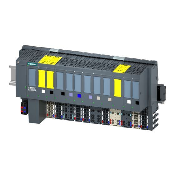
Product overview Properties Article number 6ES7136-6BA01-0CA0 View of the module ① Module type and name ⑦ Function class ② LED for diagnostics ⑧ Color coding module type ③ 2D matrix code ⑨ Function and firmware version ④ Wiring diagram ⑩ Color code for selecting the color identification labels ⑤... - Page 15 Product overview 2.1 Properties Properties The module has the following technical properties: • Fail-safe digital module • PROFIsafe • RIOforFA-Safety • PROFIsafe address type 2 • 8 inputs (SIL3/Cat.3/PLd) or 4 inputs (SIL3/Cat.4/PLe) • 8 outputs for sensor supply • Use of various interconnection types (1oo1, 1oo2) is possible •...
- Page 16 • Shield connection • Electronic coding element as replacement part (part number 6ES7193-6EF00-1AA0) For more information on accessories, refer to the system manual ET 200SP Distributed I/O System (https://support.industry.siemens.com/cs/ww/en/view/58649293). Digital input module F-DI 8x24VDC HF (6ES7136-6BA01-0CA0) Equipment Manual, 10/2021, A5E50578307-AA...
-
Page 17: Connecting
This section includes the block diagram of the digital input module F-DI 8×24VDC HF with the terminal assignment. You can find information on wiring the BaseUnit in the ET 200SP Distributed I/O System (https://support.industry.siemens.com/cs/ww/en/view/58649293) system manual. Digital input module F-DI 8x24VDC HF (6ES7136-6BA01-0CA0) Equipment Manual, 10/2021, A5E50578307-AA... - Page 18 Connecting 3.1 Wiring and block diagram Block diagram The following figure shows the pin assignment of the digital input module F-DI 8×24VDC HF on the BaseUnit BU type A0. ① Backplane bus interface Internal sensor supply, channel n ② Input electronics P1, P2, Internal self-configuring voltage buses Connection to left (dark BaseUnit)
-
Page 19: Parameters/Address Space
Parameters/address space Parameters Parameter for F-DI 8x24VDC HF WARNING Diagnostics functions should be activated or deactivated in accordance with the application, see section Applications of the F-I/O module (Page 37). The following parameters are possible: Table 4- 1 Adjustable parameters Parameters Value range Default... - Page 20 Parameters/address space 4.1 Parameters Parameters Value range Default Parameter Scope reassignment in F-I/O DB name — Is proposed by the F- Module system DI parameters: Sensor supply Sensor supply n Short-circuit test Enable Channel • Disable • Enable Time for short-circuit test 0.5 ms to 2 s 4.2 ms Channel...
- Page 21 Parameters/address space 4.1 Parameters Parameters Value range Default Parameter Scope reassignment in Input delay 3.2 ms Channel • 0.4 ms • 0.8 ms • 1.6 ms • 3.2 ms • 6.4 ms • 10.0 ms • 12.8 ms • 20 ms The provided value range depends on the parameter assignment...
-
Page 22: Explanation Of Parameters
Information on the F-parameters for the F-monitoring time, the PROFIsafe addressing (F- source address, F-destination address) and the F-I/O DB can be found in the manual SIMATIC Safety - Configuring and Programming (https://support.industry.siemens.com/cs/ww/en/view/54110126). See also S7 Distributed Safety - Configuring and Programming (https://support.industry.siemens.com/cs/ww/en/view/22099875) -
Page 23: Reintegration After Channel Fault
Parameters/address space 4.2 Explanation of parameters 4.2.1.3 Reintegration after channel fault Use this parameter to select how the channels of the fail-safe module are reintegrated after a fault. Use on S7-300/400 F-CPUs This parameter is always set to "Adjustable" when you use the fail-safe module in S7-300/400 F-CPUs. -
Page 24: Parameters Of The Sensor Supply
Parameters/address space 4.2 Explanation of parameters 4.2.2 Parameters of the sensor supply 4.2.2.1 Short-circuit test Here you activate the short-circuit detection for the channels of the F-module for which an internal sensor supply is set. The short-circuit test can always be performed when you use simple switches which do not have an own power supply. -
Page 25: Time For Short-Circuit Test
Parameters/address space 4.2 Explanation of parameters 4.2.2.2 Time for short-circuit test Function When the short-circuit test is enabled, the corresponding sensor supply is switched off for the configured time. If the module does not detect a "0" signal at the input within the assigned time, a diagnostic message is generated. -
Page 26: Parameters Of The Channel Pairs
Parameters/address space 4.2 Explanation of parameters 4.2.3 Parameters of the channel pairs 4.2.3.1 Sensor evaluation Overview Select the type of sensor evaluation with the "Sensor evaluation" parameter: • 1oo1 evaluation • 1oo2 evaluation, equivalent • 1oo2 evaluation, non-equivalent 1oo1 evaluation The sensor uses only one input channel for the 1oo1 evaluation. -
Page 27: Discrepancy Behavior
Parameters/address space 4.2 Explanation of parameters 4.2.3.2 Discrepancy behavior Function For the "Discrepancy behavior", you assign the value that is supplied to the safety program in the F-CPU during a discrepancy between two relevant input channels, which means while discrepancy time is running. You assign the discrepancy behavior as follows: •... -
Page 28: Discrepancy Time
Parameters/address space 4.2 Explanation of parameters 4.2.3.3 Discrepancy time Function You can set the discrepancy time for each channel pair. Requirements You have assigned the following: • "Sensor evaluation": "1oo2 evaluation, equivalent" or "1oo2 evaluation, non-equivalent" In most cases, a discrepancy time is started, but does not fully expire because the signal differences are cleared within a short time. -
Page 29: Reintegration After Discrepancy Error
Parameters/address space 4.2 Explanation of parameters 4.2.3.4 Reintegration after discrepancy error Function This parameter specifies the criteria for when a discrepancy error is regarded as corrected, thus enabling reintegration of the relevant input channels. The following parameter assignment options are available: •... -
Page 30: Parameters Of The Channels
For S7-300/400 F-CPUs you set the corresponding property at the F-I/O DB by means of the ACK_NEC tag. For detailed information about the F-I/O DB, refer to the SIMATIC Safety – Configuring and Programming (https://support.industry.siemens.com/cs/ww/en/view/54110126) manual. Digital input module F-DI 8x24VDC HF (6ES7136-6BA01-0CA0) Equipment Manual, 10/2021, A5E50578307-AA... -
Page 31: Sensor Supply
(see section "Electromagnetic compatibility" in the system manual ET 200SP distributed I/O system (https://support.industry.siemens.com/cs/ww/en/view/58649293)). Adapt the input delay or use shielded signal lines in order to prevent possible passivation of the fail-safe digital inputs and switch-off of the sensor supply. -
Page 32: Chatter Monitoring
Parameters/address space 4.2 Explanation of parameters 4.2.4.5 Chatter monitoring Function Chatter monitoring is a process control function for digital input signals. It detects and reports unusual signal sequences in the process with 1oo1 evaluation, for example, an input signal fluctuating between "0" and "1" too frequently. The occurrence of such signal characteristics is an indication of faulty sensors or process control instability. -
Page 33: Number Of Signal Changes
Parameters/address space 4.3 Address space 4.2.4.6 Number of signal changes Defines the number of signal changes after whose sequence a chatter error is to be reported. 4.2.4.7 Monitoring window Sets the time for the monitoring window of chatter monitoring. You can set times of 1 s to 100 s in whole seconds for the monitoring window. If you parameterize 0 s, the monitoring window is 0.5 s long. - Page 34 1oo2 evaluation of the sensors, you must only access the low-order channel in the safety program, in this example DI Additional information For detailed information about F-I/O access, refer to the SIMATIC Safety – Configuring and Programming (https://support.industry.siemens.com/cs/ww/en/view/54110126) manual. See also S7 Distributed Safety - Configuring and Programming (https://support.industry.siemens.com/cs/ww/en/view/22099875)
-
Page 35: Applications Of The F-I/O Module
Applications of the F-I/O module Applications of the electronic module Selecting the application The diagram below supports you in selecting the application that suits your fail-safe requirements. In the following sections, you will learn how to wire the F-module, the specific parameters you must assign in STEP 7 Safety and the errors that are detected. - Page 36 Information on the safety-oriented use of sensors can be found in the section Requirements for sensors and actuators for fail-safe modules and fail-safe motor starters in the system manual ET 200SP Distributed I/O System (https://support.industry.siemens.com/cs/ww/en/view/58649293). Digital input module F-DI 8x24VDC HF (6ES7136-6BA01-0CA0) Equipment Manual, 10/2021, A5E50578307-AA...
-
Page 37: Application 1: Safety Mode Sil3/Cat.3/Pld
Applications of the F-I/O module 5.2 Application 1: Safety mode SIL3/Cat.3/PLd Application 1: Safety mode SIL3/Cat.3/PLd Wiring The wiring is carried out on the matching BaseUnit. Sensor supply The sensor supply can be internal or external. Wiring diagram – connecting one sensor via one channel Per process signal, one sensor is connected via one channel (1oo1 evaluation). - Page 38 Applications of the F-I/O module 5.2 Application 1: Safety mode SIL3/Cat.3/PLd WARNING To achieve SIL3/Cat.3/PLd using this wiring, you must use a qualified sensor. WARNING To achieve SIL3/Cat.3/PLd with this wiring, you have to route the cables cross-circuit proof and apply the positive opening operation principle for the sensor. Parameter assignment Assign the following parameters for the corresponding channel: Table 5- 2...
- Page 39 Applications of the F-I/O module 5.2 Application 1: Safety mode SIL3/Cat.3/PLd Fault detection The following table presents fault detection according to the sensor supply and the parameter assignment for the short-circuit test: Table 5- 3 Fault detection Fault Fault detection Internal sensor supply Internal sensor supply External sensor...
-
Page 40: Application 2: Safety Mode Sil3/Cat.3/Ple
Applications of the F-I/O module 5.3 Application 2: Safety mode SIL3/Cat.3/PLe Application 2: Safety mode SIL3/Cat.3/PLe Assigning inputs to each other The digital input module F-DI 8×24VDC HF has 8 fail-safe inputs, DI to DI (SIL3). You can combine two of these inputs each to one input. You can combine the following inputs: •... - Page 41 Applications of the F-I/O module 5.3 Application 2: Safety mode SIL3/Cat.3/PLe Figure 5-3 A two-channel sensor connected via two channels, internal and external sensor supply WARNING To achieve SIL3/Cat.3/PLe using this wiring, you must use a suitably qualified sensor. Wiring diagram - connecting two one-channel sensors equivalent via two channels Per process signal, two one-channel sensors, which record the same process value, are connected equivalent via two channels to two inputs of the F-module (1oo2 evaluation).
- Page 42 Applications of the F-I/O module 5.3 Application 2: Safety mode SIL3/Cat.3/PLe Figure 5-4 Two one-channel sensors connected via two channels, internal and external sensor supply WARNING To achieve SIL3/Cat.3/PLe using this wiring, you must use a qualified sensor. Digital input module F-DI 8x24VDC HF (6ES7136-6BA01-0CA0) Equipment Manual, 10/2021, A5E50578307-AA...
- Page 43 Applications of the F-I/O module 5.3 Application 2: Safety mode SIL3/Cat.3/PLe Parameter assignment Assign the following parameters for the corresponding channel: Table 5- 4 Parameter assignment Parameter Channel with internal sensor Channel with external sensor supply supply Sensor evaluation 1oo2 evaluation, equivalent Sensor supply Sensor supply n External sensor supply*...
-
Page 44: Application 3: Safety Mode Sil3/Cat.4/Ple
Applications of the F-I/O module 5.4 Application 3: Safety mode SIL3/Cat.4/PLe Application 3: Safety mode SIL3/Cat.4/PLe Assigning inputs to each other The digital input module F-DI 8×24VDC HF has 8 fail-safe inputs, DI to DI (SIL3). You can combine two of these inputs each to one input. You can combine the following inputs: •... -
Page 45: Application 3.1: Safety Mode Sil3/Cat.4/Ple
Applications of the F-I/O module 5.4 Application 3: Safety mode SIL3/Cat.4/PLe 5.4.1 Application 3.1: Safety mode SIL3/Cat.4/PLe Wiring diagram - connecting a two-channel sensor equivalent via two channels Per process signal, a two-channel sensor is connected equivalent via two channels to two inputs of the F-module (1oo2 evaluation). - Page 46 Applications of the F-I/O module 5.4 Application 3: Safety mode SIL3/Cat.4/PLe Wiring diagram - connecting two one-channel sensors equivalent via two channels Per process signal, two one-channel sensors, which record the same process value, are connected equivalent via two channels to two inputs of the F-module (1oo2 evaluation). Supply the sensors from two different internal sensor supplies or from an internal and an external sensor supply.
- Page 47 Applications of the F-I/O module 5.4 Application 3: Safety mode SIL3/Cat.4/PLe Parameter assignment Assign the following parameters for the corresponding channel: Table 5- 6 Parameter assignment Parameter Channel with internal Channel with external sensor supply sensor supply* Sensor evaluation 1oo2 evaluation, equivalent Sensor supply Sensor supply n External sensor supply**...
-
Page 48: Application 3.2: Safety Mode Sil3/Cat.4/Ple
Applications of the F-I/O module 5.4 Application 3: Safety mode SIL3/Cat.4/PLe 5.4.2 Application 3.2: Safety mode SIL3/Cat.4/PLe Wiring diagram – connecting a non-equivalent sensor Per process signal, a non-equivalent sensor is connected to two inputs of the F-module (1oo2 evaluation). You can supply the sensor via an internal or external sensor supply. - Page 49 Applications of the F-I/O module 5.4 Application 3: Safety mode SIL3/Cat.4/PLe Wiring diagram - connecting two one-channel sensors non-equivalent via two channels Per process signal, two one-channel sensors, which record the same process value, are connected non-equivalent via two channels to two inputs of the F-module (1oo2 evaluation). Any sensor supply of the module can be assigned to each input.
- Page 50 Applications of the F-I/O module 5.4 Application 3: Safety mode SIL3/Cat.4/PLe Parameter assignment Assign the following parameters for the corresponding channel: Table 5- 8 Parameter assignment Parameter Channel with internal sensor supply Channel with external sensor supply Sensor evaluation 1oo2 evaluation, non-equivalent Sensor supply Sensor supply n External sensor supply*...
-
Page 51: Interrupts/Diagnostic Messages
Interrupts/diagnostic messages Status and error display LED display The following figure shows you the LED display of the F-DI 8x24VDC HF. ① DIAG (green/red) ② Channel status (green) ③ Channel error (red) ④ PWR (green) Figure 6-1 LED display Meaning of the LED displays The following tables explain the meaning of the status and error displays. - Page 52 Interrupts/diagnostic messages 6.1 Status and error display DIAG LED Table 6- 1 DIAG LED fault display DIAG Meaning Backplane bus supply of the ET 200SP not okay Module parameters not configured Flashing Module parameters configured and no module diagnostics • Module parameters configured and module diagnostics Flashing •...
- Page 53 Interrupts/diagnostic messages 6.1 Status and error display Channel status/DIAG/channel fault LED Table 6- 3 Status display of the LED channel status/DIAG/channel fault Channel DIAG Channel Meaning status fault The PROFIsafe address does not match the PROFIsafe address of the configuration or there is a module-wide error. See section All On Flashin Interrupts (Page 56)
-
Page 54: Interrupts
Interrupts/diagnostic messages 6.2 Interrupts Interrupts Introduction The fail-safe digital input module F-DI 8×24VDC HF supports diagnostic interrupts. Diagnostic interrupt The F-module generates a diagnostic interrupt for each diagnostic message described in section Diagnostic messages (Page 58). The following list provides you with an overview of the diagnostic interrupts of the F-module. The diagnostic interrupts are assigned either to one channel or the entire F-module. - Page 55 Interrupts/diagnostic messages 6.2 Interrupts • Invalid/inconsistent firmware present • Diagnostic queue overflow • Undertemperature • Supply voltage too high • Supply voltage too low • F-module error (0x032F) Channel-wide diagnostic interrupts • Discrepancy failure, channel status 0/0 • Discrepancy failure, channel status 0/1 •...
-
Page 56: Diagnostic Messages
Once the fault is eliminated, the F-module must be reintegrated in the safety program. For additional information on passivation and reintegration of F-I/O, refer to the SIMATIC Safety – Configuring and Programming (https://support.industry.siemens.com/cs/ww/en/view/54110126) manual. Table 6- 5 Diagnostics messages of the F-DI 8x24VDC HF... - Page 57 Interrupts/diagnostic messages 6.3 Diagnostic messages Diagnostic message Fault Meaning Remedy code Parameter F_CRC_Length The PROFIsafe driver has detected a does not match the discrepancy in the CRC length. generated values Version of F parameter set The PROFIsafe driver has detected an incorrect incorrect version of the F-parameters or an invalid F_Block_ID.
- Page 58 Interrupts/diagnostic messages 6.3 Diagnostic messages Diagnostic message Fault Meaning Remedy code Diagnostic queue overflow Overflow of the diagnostic memory. Not Eliminate the previously reported error. all pending diagnostics could be sent. This error can result in deactivation of the module up to switching on/off of the power supply.
- Page 59 Interrupts/diagnostic messages 6.3 Diagnostic messages Diagnostic message Fault Meaning Remedy code Overload or internal sensor Possible causes: • Eliminate the overload. supply short-circuit to ground • The internal sensor supply is short- • Eliminate the short-circuit in the circuited to ground. process wiring.
- Page 60 Generally applicable information on diagnostics For information on diagnostics which apply to all F-modules (e.g. reading out the diagnostic functions, passivation of channels), refer to the SIMATIC Safety - Configuring and Programming (https://support.industry.siemens.com/cs/ww/en/view/54110126) manual. See also S7 Distributed Safety - Configuring and Programming (https://support.industry.siemens.com/cs/ww/en/view/22099875)
-
Page 61: Value Status
You can find the assignment in section Address space (Page 35). Reference A detailed description of the evaluation and processing of the value status can be found in the SIMATIC Safety – Configuring and Programming (https://support.industry.siemens.com/cs/ww/en/view/54110126) manual. Digital input module F-DI 8x24VDC HF (6ES7136-6BA01-0CA0) Equipment Manual, 10/2021, A5E50578307-AA... - Page 62 Technical specifications Technical specifications of F-DI 8×24VDC HF The following table shows the technical specifications as of 10/2021. You can find a data sheet including updated technical specifications on the Internet (https://support.industry.siemens.com/cs/ww/en/pv/6ES7136-6BA01-0CA0/td?dl=en). Article number 6ES7136-6BA01-0CA0 General information Product type designation...
-
Page 63: Technical Specifications
Technical specifications Article number 6ES7136-6BA01-0CA0 Power loss Power loss, typ. Address area Address space per module 7 byte; S7-300/400F CPU, 6 byte • Inputs 5 byte; S7-300/400F CPU, 4 byte • Outputs Hardware configuration Automatic encoding • Electronic coding element type F Digital inputs Number of digital inputs Source/sink input... - Page 64 Technical specifications Article number 6ES7136-6BA01-0CA0 Yes; green PWR LED • Monitoring of the supply voltage (PWR-LED) Yes; green LED • Channel status display Yes; red LED • for channel diagnostics Yes; green/red DIAG LED • for module diagnostics Potential separation Potential separation channels •...
- Page 65 Technical specifications Dimension drawing See the Equipment Manual ET 200SP BaseUnits (https://support.industry.siemens.com/cs/ww/en/view/59753521). Digital input module F-DI 8x24VDC HF (6ES7136-6BA01-0CA0) Equipment Manual, 10/2021, A5E50578307-AA...
- Page 66 F-DI 8×24VDC HF are included in the calculation of the response time of the F-system. To do this, use the SIMATIC STEP7 response time table (https://support.industry.siemens.com/cs/ww/en/view/93839056). WARNING If you have configured the digital input module F-DI 8x24VDC HF (6ES7136-6BA00-0CA0) in...
-
Page 67: Response Times
Response times Maximum response time in an error-free scenario (worst case delay time, WCDT) for 1oo2 evaluation. The following formula applies to a sensor supply without short-circuit test: Maximum response time (T ) = 2 * T + Input delay+ Discrepancy time* WCDT cycle The following formula applies to a sensor supply with short-circuit test:... - Page 68 Response times x = Sensor supply T1x = Time for short-circuit test T2x = Startup time of sensor after short-circuit test n = Number of sensor supplies with activated short-circuit test The following section provides two examples for the calculation of the maximum response time to external short-circuits at an F-DI 8×24VDC HF, depending on the parameter assignment.
- Page 69 Response times Maximum response time for discrepancy error for 1oo2 evaluation (one fault delay time, OFDT) Maximum response time (T ) = 2 * T + Input delay + 2 * max (T1p + T2p, T1s + T2s) + OFDT cycle Discrepancy time T1p = Time for short-circuit test (sensor 1)