Dell EMC PowerEdge R730xd Owner's Manual
Hide thumbs
Also See for EMC PowerEdge R730xd:
- Owner's manual (239 pages) ,
- Deployment manual (78 pages) ,
- Technical manual (64 pages)

Related Manuals for Dell EMC PowerEdge R730xd


Summary of Contents for Dell EMC PowerEdge R730xd
- Page 1 Dell PowerEdge R730xd Owner's Manual Regulatory Model: E31S Series Regulatory Type: E31S001 July 2021 Rev. A06...
- Page 2 A WARNING indicates a potential for property damage, personal injury, or death. © 2017 2020 Dell Inc. or its subsidiaries. All rights reserved. Dell, EMC, and other trademarks are trademarks of Dell Inc. or its subsidiaries. Other trademarks may be trademarks of their respective owners.
-
Page 3: Table Of Contents
Contents Chapter 1: Dell PowerEdge R730xd system overview..............8 Supported configurations for the PowerEdge R730xd system................8 Front panel...................................10 24 x 2.5-inch hard drive/SSD chassis........................10 12 x 3.5-inch hard drive............................... 11 8 x 3.5-inch hard drive and 18 x 1.8-inch SSD...................... 13 Back panel....................................14... - Page 4 System Setup..................................37 Viewing System Setup............................... 38 System Setup details..............................38 System BIOS.................................38 iDRAC Settings utility..............................63 Device Settings................................64 Dell Lifecycle Controller..............................64 Embedded systems management..........................64 Boot Manager..................................65 Viewing Boot Manager...............................65 Boot Manager main menu............................65 PXE boot..................................... 66 Chapter 6: Installing and removing system components..............
- Page 5 Cooling fan assembly ...............................88 Removing the cooling fan assembly........................88 Installing the cooling fan assembly..........................89 System memory.................................90 General memory module installation guidelines....................92 Mode-specific guidelines............................92 Sample memory configurations..........................93 Removing memory modules............................96 Installing memory modules............................97 Processors and heat sinks.............................. 99 Removing a heat sink..............................
- Page 6 Chapter 7: Using system diagnostics..................195 Dell Embedded System Diagnostics..........................195 When to use the Embedded System Diagnostics....................195 Running the Embedded System Diagnostics from Boot Manager..............195 Running the Embedded System Diagnostics from the Dell Lifecycle Controller........195 System diagnostic controls............................. 196 Contents...
- Page 7 System messages................................214 Warning messages..............................214 Diagnostic messages..............................214 Alert messages................................215 Chapter 10: Getting help......................216 Contacting Dell EMC..............................216 Documentation feedback...............................216 Accessing system information by using QRL......................216 Quick Resource Locator for PowerEdge R730 and R730xd systems............217 Contents...
-
Page 8: Chapter 1: Dell Poweredge R730Xd System Overview
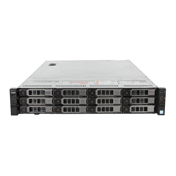
Dell PowerEdge R730xd system overview The Dell PowerEdge R730xd systems are 2U rack servers that support up to two Intel Xeon E5-2600 v3 or Xeon E5-2600 v4 processors, up to 24 DIMMs, and 28 hard drives or solid state drives (SSDs). - Page 9 Figure 1. Supported configurations for the PowerEdge R730xd system Dell PowerEdge R730xd system overview...
-
Page 10: Front Panel
This button can be pressed by using the end of a paper clip. Use this button only if directed to do so by NOTE: qualified support personnel or by instructions in the operating system’s documentation. Dell PowerEdge R730xd system overview... -
Page 11: 12 X 3.5-Inch Hard Drive
Direct to connect USB devices to the system or provides access to the iDRAC Direct features. For more information, see the Integrated Dell Remote Access Controller User’s Guide at Dell.com/idracmanuals. Video connector Enables you to connect a display to the system. - Page 12 Direct to connect USB devices to the system or provides access to the iDRAC Direct features. For more information, see the Integrated Dell Remote Access Controller User’s Guide at Dell.com/idracmanuals. Video connector Enables you to connect a display to the system.
-
Page 13: X 3.5-Inch Hard Drive And 18 X 1.8-Inch Ssd
NOTE: qualified support personnel or by instructions in the operating system’s documentation. Information tag Contains system information such as service tag, NIC, MAC address for your reference. The information tag is a slide-out label panel. Dell PowerEdge R730xd system overview... -
Page 14: Back Panel
Direct to connect USB devices to the system or provides access to the iDRAC Direct features. For more information, see the Integrated Dell Remote Access Controller User’s Guide at Dell.com/idracmanuals. Video connector Enables you to connect a display to the system. -
Page 15: Diagnostic Indicators On The Front Panel
Hard drive (2) (back) Diagnostic indicators on the front panel No diagnostic indicators are lit when the system is turned off. To start the system, plug it into a working power NOTE: source and press the power button. Dell PowerEdge R730xd system overview... - Page 16 Check the System Event Log or system messages for the specific issue. For more information ● When the system is turned on. about error messages, see the Dell Event and ● When the system is in standby. Error Messages Reference Guide at Dell.com/ ●...
-
Page 17: Hard Drive Indicator Codes
Flashes amber four times per second Drive failed Flashes green slowly Drive rebuilding Steady green Drive online Rebuild stopped Flashes green for three seconds, amber for three seconds, and then turns off after six seconds Dell PowerEdge R730xd system overview... -
Page 18: Usata Ssd Indicator Codes
Flashes green, amber, and turns off Predicted drive failure Flashes amber four times per second Drive failed Steady green Drive online Flashes green for three seconds, amber for three Rebuild aborted seconds, and turns off after six seconds Dell PowerEdge R730xd system overview... -
Page 19: Nic Indicator Codes
AC power supply units (PSUs) have an illuminated translucent handle that serves as an indicator and DC PSUs have an LED that serves as an indicator. The indicator shows whether power is present or a power fault has occurred. Dell PowerEdge R730xd system overview... - Page 20 For AC PSUs, use only PSUs with the Extended Power Performance (EPP) label on the back. Mixing PSUs from previous generations of Dell PowerEdge servers can NOTE: result in a PSU mismatch condition or failure to turn the system on.
-
Page 21: Idrac Direct Led Indicator Codes
The iDRAC Direct LED indicator lights up to indicate that the port is connected and is being used as a part of the iDRAC subsystem. The iDRAC Direct LED indicator does not turn on when the USB port is used in the USB mode. NOTE: Dell PowerEdge R730xd system overview... - Page 22 Indicates that the laptop is connected. Solid green for two seconds Flashing green (on for two seconds Indicates that the laptop connected is recognized. and off for two seconds) Turns off Indicates that the laptop is unplugged. Dell PowerEdge R730xd system overview...
-
Page 23: Quick Sync Indicator Codes
Tag are found on the front of the system by pulling out the information tag. Alternatively, the information may be on a sticker on the chassis of the system. This information is used by Dell to route support calls to the appropriate personnel. -
Page 24: Chapter 2: Documentation Resources
This section provides information about the documentation resources for your system. To view the document that is listed in the documentation resources table: ● From the Dell EMC support site: 1. Click the documentation link that is provided in the Location column in the table. - Page 25 Methods to download firmware and drivers section in this document. Managing your For information about systems www.dell.com/poweredgemanuals system management software offered by Dell, see the Dell OpenManage Systems Management Overview Guide. For information about setting www.dell.com/ up, using, and troubleshooting openmanagemanuals >...
- Page 26 Table 14. Additional documentation resources for your system (continued) Task Document Location Troubleshooting your For information about identifying www.dell.com/poweredgemanuals system and troubleshooting the PowerEdge server issues, see the Server Troubleshooting Guide. Documentation resources...
-
Page 27: Chapter 3: Technical Specifications
Technical specifications The technical and environmental specifications of your system are outlined in this section. Topics: • Chassis dimensions • Chassis weight • Processor specifications • PSU specifications • System battery specifications • Expansion bus specifications • Memory specifications • Drive specifications •... -
Page 28: Chassis Weight
Table 15. Dimensions of the Dell PowerEdge R730xd system Za (with Za (without bezel) bezel) 482.4 mm 444.0 mm 87.3 mm 32.0 mm 18.0 mm 684.0 mm 723.0 mm Chassis weight This section describes the weight of the system. Table 16. Chassis weight... -
Page 29: Expansion Bus Specifications
Expansion bus specifications The PowerEdge R730xd system supports PCI express (PCIe) generation 3 expansion cards, which need to be installed on the system board using expansion card risers. This system supports three types of expansion card risers. The following table provides the expansion card riser specifications: Table 18. -
Page 30: Ports And Connectors Specifications
Table 20. Supported hard drive and SSD options for the PowerEdge R730xd system (continued) Drives Specifications Up to twenty 2.5-inch hard drives, up to four 2.5-inch (U.2) NVMe drives (in slots 20 to 23) and up to two optional 2.5- inch back-accessible hard drives. -
Page 31: Video Specifications
8, 16, 32 1280x1024 60,75 8, 16, 32 1440x900 8, 16, 32 Environmental specifications For additional information about environmental measurements for specific system configurations, see Dell.com/ NOTE: environmental_datasheets. Table 23. Temperature specifications Temperature Specifications Storage –40°C to 65°C (–40°F to 149°F) Continuous operation (for altitude less than 950 m or 10°C to 35°C (50°F to 95°F) with no direct sunlight on the... -
Page 32: Particulate And Gaseous Contamination Specifications
Table 27. Maximum altitude specifications Maximum altitude Specifications Operating 30482000 m (10,0006560 ft) Storage 12,000 m (39,370 ft) Table 28. Operating temperature de-rating specifications Operating temperature de-rating Specifications Up to 35°C (95°F) Maximum temperature is reduced by 1°C/300 m (1°F/547 ft) above 950 m (3,117 ft). -
Page 33: Standard Operating Temperature
● 160 W or higher wattage processor is not supported. ● Redundant power supply units are required. ● Non-Dell qualified peripheral cards and/or peripheral cards greater than 25 W are not supported. ● The 3.5-inch hard drive chassis supports a maximum of 120 W processor. -
Page 34: Chapter 4: Initial System Setup And Configuration
The Integrated Dell Remote Access Controller (iDRAC) is designed to make system administrators more productive and improve the overall availability of Dell EMC systems. iDRAC alerts administrators to system issues, helps them perform remote system management, and reduces the need for physical access to the system. -
Page 35: Options To Install The Operating System
You must have iDRAC credentials to log in to iDRAC. NOTE: For more information about logging in to iDRAC and iDRAC licenses, see the latest Integrated Dell Remote Access Controller User's Guide at Dell.com/idracmanuals. Options to install the operating system... -
Page 36: Manage Your System
Downloading the drivers and firmware Dell EMC recommends that you download and install the latest BIOS, drivers, and systems management firmware on your system. Prerequisites Ensure that you clear the web browser cache before downloading the drivers and firmware. Steps 1. -
Page 37: Chapter 5: Pre-Operating System Management Applications
Options to manage the pre-operating system applications Your system has the following options to manage the pre-operating system applications: ● System Setup ● Boot Manager ● Dell Lifecycle Controller ● Preboot Execution Environment (PXE) Related concepts System Setup on page 37... -
Page 38: Viewing System Setup
The iDRAC settings utility is an interface to set up and configure the iDRAC parameters by using UEFI (Unified Extensible Firmware Interface). You can enable or disable various iDRAC parameters by using the iDRAC settings utility. For more information about this utility, see Integrated Dell Remote Access Controller User’s Guide at Dell.com/idracmanuals. - Page 39 System Information on page 49 Memory Settings on page 50 Processor Settings on page 51 SATA Settings on page 53 Integrated Devices on page 56 Serial Communication on page 59 System Profile Settings on page 60 Miscellaneous Settings on page 62 iDRAC Settings utility on page 63 Device Settings...
- Page 40 Option Description Specifies options to change the processor power management settings, memory frequency, and so on. System Profile Settings Specifies options to configure the system security settings, such as system password, setup password, System Security Trusted Platform Module (TPM) security. It also manages the power and NMI buttons on the system. Specifies options to change the system date, time, and so on.
- Page 41 Boot Settings details About this task The Boot Settings screen details are explained as follows: Option Description Enables you to set the boot mode of the system. Boot Mode CAUTION: Switching the boot mode may prevent the system from booting if the operating system is not installed in the same boot mode.
- Page 42 ● Operating systems must be UEFI-compatible to be installed from the UEFI boot mode. DOS and 32-bit operating systems do not support UEFI and can only be installed from the BIOS boot mode. ● For the latest information about supported operating systems, go to Dell.com/ossupport. Related references...
- Page 43 Viewing Network Settings To view the Network Settings screen, perform the following steps: Steps 1. Turn on, or restart your system. 2. Press F2 immediately after you see the following message: F2 = System Setup If your operating system begins to load before you press F2, wait for the system to finish booting, and then NOTE: restart your system and try again.
- Page 44 Viewing UEFI iSCSI Settings To view the UEFI iSCSI Settings screen, perform the following steps: Steps 1. Turn on, or restart your system. 2. Press F2 immediately after you see the following message: F2 = System Setup If your operating system begins to load before you press F2, wait for the system to finish booting, and then NOTE: restart your system and try again.
- Page 45 Viewing System Security To view the System Security screen, perform the following steps: Steps 1. Turn on, or restart your system. 2. Press F2 immediately after you see the following message: F2 = System Setup If your operating system begins to load before you press F2, wait for the system to finish booting, and then NOTE: restart your system and try again.
- Page 46 Option Description Sets the time delay for the system to power up after AC power is restored to the system. This option is AC Power set to Immediate by default. Recovery Delay Sets the User Defined Delay option when the User Defined option for AC Power Recovery Delay is User Defined selected.
- Page 47 Secure Boot Custom Policy Settings details The Secure Boot Custom Policy Settings screen details are explained as follows: Option Description Imports, exports, deletes, or restores the platform key (PK). Platform Key Enables you to import, export, delete, or restore entries in the Key Exchange Key (KEK) Database. Key Exchange Key Database Imports, exports, deletes, or restores entries in the Authorized Signature Database (db).
- Page 48 Steps 1. Turn on or reboot your system. 2. Type the system password and press Enter. Next steps When Password Status is set to Locked, type the system password and press Enter when prompted at reboot. If an incorrect system password is typed, the system displays a message and prompts you to reenter your password. NOTE: You have three attempts to type the correct password.
- Page 49 System Information You can use the System Information screen to view system properties such as Service Tag, system model name, and the BIOS version. Related references System Information details on page 49 System BIOS on page 38 Related tasks Viewing System Information on page 49 Viewing System Information To view the System Information screen, perform the following steps:...
- Page 50 Option Description Specifies the current version of the system complex programmable logic device (CPLD) firmware. System CPLD Version Specifies the UEFI compliance level of the system firmware. UEFI Compliance Version Related references System Information on page 49 System Information details on page 49 Related tasks Viewing System Information...
- Page 51 Specifies the memory operating mode. The options available are Optimizer Mode, Advanced ECC Memory Mode, Mirror Mode, Spare Mode, Spare with Advanced ECC Mode, Dell Fault Resilient Mode and Operating Mode Dell NUMA Fault Resilient Mode. This option is set to Optimizer Mode by default.
- Page 52 Viewing Processor Settings To view the Processor Settings screen, perform the following steps: Steps 1. Turn on, or restart your system. 2. Press F2 immediately after you see the following message: F2 = System Setup If your operating system begins to load before you press F2, wait for the system to finish booting, and then NOTE: restart your system and try again.
- Page 53 Enables or disables the X2Apic mode. X2Apic Mode Controls the turbo engagement. Enable this option only when System Profile is set to Performance. Dell Controlled Turbo Depending on the number of installed CPUs, there may be up to four processor listings.
- Page 54 Viewing SATA Settings To view the SATA Settings screen, perform the following steps: Steps 1. Turn on, or restart your system. 2. Press F2 immediately after you see the following message: F2 = System Setup If your operating system begins to load before you press F2, wait for the system to finish booting, and then NOTE: restart your system and try again.
- Page 55 Option Description Sets the drive type of the selected device. For Embedded SATA settings in ATA mode, set this field to Port C Auto to enable BIOS support. Set it to OFF to turn off BIOS support. For AHCI or RAID mode, BIOS support is always enabled. Option Description Specifies the drive model of the selected device.
- Page 56 Option Description Sets the drive type of the selected device. For Embedded SATA settings in ATA mode, set this field to Port H Auto to enable BIOS support. Set it to OFF to turn off BIOS support. For AHCI or RAID mode, BIOS support is always enabled. Option Description Specifies the drive model of the selected device.
- Page 57 Viewing Integrated Devices To view the Integrated Devices screen, perform the following steps: Steps 1. Turn on, or restart your system. 2. Press F2 immediately after you see the following message: F2 = System Setup If your operating system begins to load before you press F2, wait for the system to finish booting, and then NOTE: restart your system and try again.
- Page 58 Option Description Enables or disables the Embedded Video Controller option. This option is set to Enabled by default. Embedded Video Controller Displays the current state of the embedded video controller. The Current State of Embedded Video Current State of Controller option is a read-only field. If the Embedded Video Controller is the only display capability in the Embedded Video system (that is, no add-in graphics card is installed), then the Embedded Video Controller is automatically Controller...
- Page 59 Related tasks Viewing Integrated Devices on page 57 Serial Communication You can use the Serial Communication screen to view the properties of the serial communication port. Related references System BIOS on page 38 Related tasks Serial Communication details on page 59 Viewing Serial Communication on page 59 Viewing Serial Communication...
- Page 60 Option Description within the BIOS setup utility may not always revert the serial MUX setting to the default setting of Serial Device 1. External Serial Enables you to associate the External Serial Connector to Serial Device 1, Serial Device 2, or the Remote Connector Access Device by using this option.
- Page 61 You can only change the rest of the options if the mode is set to Custom. This option is set to Performance Per Watt Optimized (DAPC) by default. DAPC is Dell Active Power Controller.
- Page 62 Option Description Controls the number of turbo boost enabled cores for processor 1. The maximum number of cores is Enabled Cores enabled by default. for Processor 1 Enables the Monitor/Mwait instructions in the processor. This option is set to Enabled for all system Monitor/Mwait profiles, except Custom by default.
-
Page 63: Idrac Settings Utility
Accessing some of the features on the iDRAC settings utility needs the iDRAC Enterprise License upgrade. NOTE: For more information about using iDRAC, see Dell Integrated Dell Remote Access Controller User's Guide at Dell.com/ idracmanuals. -
Page 64: Device Settings
Dell Lifecycle Controller Dell Lifecycle Controller (LC) provides advanced embedded system management capabilities including system deployment, configuration, update, maintenance, and diagnosis. LC is delivered as part of the iDRAC out-of-band solution and Dell EMC system embedded Unified Extensible Firmware Interface (UEFI) applications. -
Page 65: Boot Manager
Certain platform configurations may not support the full set of features provided by the Dell Lifecycle Controller. NOTE: For more information about setting up the Dell Lifecycle Controller, configuring hardware and firmware, and deploying the operating system, see the Dell Lifecycle Controller documentation at Dell.com/idracmanuals. -
Page 66: Pxe Boot
Related references Boot Manager on page 65 Related tasks Viewing Boot Manager on page 65 One-shot BIOS boot menu One-shot BIOS boot menu enables you to select a boot device to boot from. Related references Boot Manager on page 65 System Utilities System Utilities contains the following utilities that can be launched: ●... -
Page 67: Chapter 6: Installing And Removing System Components
Damage due to servicing that is not authorized by Dell is not covered by your warranty. Read and follow the safety instructions that are shipped with your product. -
Page 68: Before Working Inside Your System
2. Disconnect the system from the electrical outlet and disconnect the peripherals. 3. If installed, remove the front bezel. 4. If applicable, remove the system from the rack. For more information, see the Rack Installation placemat at Dell.com/poweredgemanuals. 5. Remove the system cover. Related tasks... -
Page 69: Front Bezel (Optional)
● Tyco Electronics 58433-3 or equivalent ● Wire-stripper pliers to remove insulation from size 10 AWG solid or stranded, insulated copper wire Use alpha wire part number 3080 or equivalent (65/30 stranding). NOTE: Front bezel (optional) The front bezel is attached to the front side of the system and prevents accidents while removing the hard drive or when pressing the reset or power button. -
Page 70: Installing The Optional Front Bezel
Figure 15. Removing the optional Quick Sync front bezel a. release latch b. bezel lock c. Quick Sync bezel Installing the optional front bezel Prerequisites Follow the safety guidelines listed in the Safety instructions section. Steps 1. Locate and remove the bezel key. The bezel key is attached to the back of the bezel. - Page 71 Figure 16. Installing the optional front bezel a. bezel lock b. front bezel Figure 17. Installing the Quick Sync bezel a. bezel lock b. Quick Sync bezel Installing and removing system components...
-
Page 72: System Cover
System cover The system cover protects the components inside the system and helps in maintaining air flow inside the system. Removing the system cover activates the intrusion switch. Removing the system cover Prerequisites 1. Follow the safety guidelines listed in the Safety instructions section. 2. -
Page 73: Installing The System Cover
Related references Safety instructions on page 67 Related tasks Removing the optional front bezel on page 69 Installing the system cover on page 73 Installing the system cover Prerequisites 1. Follow the safety guidelines listed in the Safety instructions section. 2. -
Page 74: Inside The System
3. Turn on the system, including any attached peripherals. 4. Follow the procedure listed in the After working inside your system section. Related references Safety instructions on page 67 Related tasks Installing the optional front bezel on page 70 Inside the system Figure 20. -
Page 75: Cooling Shroud
Damage due to servicing that is not authorized by Dell is not covered by your warranty. Read and follow the safety instructions that are shipped with your product. -
Page 76: Installing The Cooling Shroud
Damage due to servicing that is not authorized by Dell is not covered by your warranty. Read and follow the safety instructions that are shipped with your product. -
Page 77: Hard Drive Tray Assembly
Damage due to servicing that is not authorized by Dell is not covered by your warranty. Read and follow the safety instructions that are shipped with your product. -
Page 78: Installing The Hard Drive Tray
Next steps 1. Install the hard drive tray. See the Installing the hard drive tray section. 2. Follow the procedure listed in the After working inside your system section. Related references Safety instructions on page 67 Related tasks Before working inside your system on page 68 Installing the hard drive tray on page 78... -
Page 79: Removing A Hard Drive Blank From A Hard Drive Carrier
Damage due to servicing that is not authorized by Dell is not covered by your warranty. Read and follow the safety instructions that are shipped with your product. -
Page 80: Installing A Hard Drive Blank Into A Hard Drive Carrier
Damage due to servicing that is not authorized by Dell is not covered by your warranty. Read and follow the safety instructions that are shipped with your product. -
Page 81: Removing A Hard Drive Carrier From The Hard Drive Tray
Damage due to servicing that is not authorized by Dell is not covered by your warranty. Read and follow the safety instructions that came with the product. -
Page 82: Installing A Hard Drive Carrier Into The Hard Drive Tray
Damage due to servicing that is not authorized by Dell is not covered by your warranty. Read and follow the safety instructions that are shipped with your product. -
Page 83: Removing A Hard Drive From A Hard Drive Carrier
Damage due to servicing that is not authorized by Dell is not covered by your warranty. Read and follow the safety instructions that are shipped with your product. -
Page 84: Installing A Hard Drive Into A Hard Drive Carrier
Damage due to servicing that is not authorized by Dell is not covered by your warranty. Read and follow the safety instructions that are shipped with your product. -
Page 85: Removing The Hard Drive Backplane From The Hard Drive Tray
Damage due to servicing that is not authorized by Dell is not covered by your warranty. Read and follow the safety instructions that are shipped with your product. -
Page 86: Installing The Hard Drive Backplane In The Hard Drive Tray
Damage due to servicing that is not authorized by Dell is not covered by your warranty. Read and follow the safety instructions that are shipped with your product. -
Page 87: Installing A Cooling Fan
Figure 32. Removing a cooling fan 1. cooling fan assembly 2. cooling fan connector (6) 3. fan release tab (6) 4. cooling fan (6) 5. cooling fan connector on the system board (6) Next steps 1. Install the cooling fan. 2. -
Page 88: Cooling Fan Assembly
Damage due to servicing that is not authorized by Dell is not covered by your warranty. Read and follow the safety instructions that are shipped with your product. -
Page 89: Installing The Cooling Fan Assembly
Damage due to servicing that is not authorized by Dell is not covered by your warranty. Read and follow the safety instructions that are shipped with your product. -
Page 90: System Memory
Figure 34. Installing the cooling fan assembly 1. cooling fan assembly 2. cooling fan (6) 3. release lever (2) 4. guide pin on the system board (2) 5. cooling fan connector (6) 6. guide pin on the chassis (6) Next steps Follow the procedure listed in the After working inside your system section. - Page 91 Your system contains 24 memory sockets split into two sets of 12 sockets, one set per processor. Each 12-socket set is organized into four channels. In each channel, the release tabs of the first socket are marked white, the second socket black, and the third socket green.
-
Page 92: General Memory Module Installation Guidelines
Table 36. Memory population (continued) DIMM Type DIMMs Operating Frequency Maximum DIMM Rank/ Populated/ Voltage (in MT/s) Channel Channel 2400, 2133, 1866 Quad rank 2133, 1866 Quad rank General memory module installation guidelines Memory configurations that fail to observe these guidelines can prevent your system from booting, stop responding NOTE: during memory configuration, or operating with reduced memory. -
Page 93: Sample Memory Configurations
Memory optimized independent channel mode This mode supports Single Device Data Correction (SDDC) only for memory modules that use x4 device width. It does not impose any specific slot population requirements. Memory sparing To use memory sparing, this feature must be enabled in System Setup. NOTE: In this mode, one rank per channel is reserved as a spare. - Page 94 Table 38. Memory configurations—single processor (continued) System DIMM size Number of DIMM rank, organization, and DIMM slot population capacity— —in GB DIMMs frequency in GB 1 R , x8, 2400 MT/s A1, A2 1 R, x8, 2133 MT/s 1 R, x8, 2400 MT/s A1, A2, A3, A4, A5, A6 1 R, x8, 2133 MT/s 1 R, x8, 1866 MT/s...
- Page 95 Table 39. Memory configurations—2 processors (continued) System DIMM size Number of DIMM rank, organization, and DIMM slot population capacity— —in GB DIMMs frequency in GB 1 R, x8, 2133 MT/s 1 R, x8, 2400 MT/s A1, A2, A3, A4, A5, A6, A7, A8, B1, B2, B3, B4, B5, B6, B7, B8 1 R, x8, 2133 MT/s 1 R, x8, 2400 MT/s...
-
Page 96: Removing Memory Modules
Damage due to servicing that is not authorized by Dell is not covered by your warranty. Read and follow the safety instructions that are shipped with your product. -
Page 97: Installing Memory Modules
Damage due to servicing that is not authorized by Dell is not covered by your warranty. Read and follow the safety instructions that are shipped with your product. - Page 98 3. Removing the cooling fan assembly. 4. Remove the cooling shroud. Steps 1. Locate the appropriate memory module socket. CAUTION: Handle each memory module only by the card edges, ensuring not to touch the middle of the memory module or metallic contacts. 2.
-
Page 99: Processors And Heat Sinks
Related references Safety instructions on page 67 Related tasks Before working inside your system on page 68 Removing the cooling shroud on page 75 Removing the cooling fan assembly on page 88 After working inside your system on page 68 Processors and heat sinks Use the following procedures when: ●... -
Page 100: Removing A Processor
Damage due to servicing that is not authorized by Dell is not covered by your warranty. Read and follow the safety instructions that are shipped with your product. - Page 101 You can update the system BIOS by using the Dell Lifecycle Controller. NOTE: To ensure proper system cooling, you must install a processor blank in any empty processor socket. NOTE: 1. Follow the safety guidelines listed in the Safety instructions section.
- Page 102 Figure 39. Processor shield 1. close first socket release lever 2. lock icon 3. processor 4. open first socket release lever 5. unlock icon Installing and removing system components...
- Page 103 Figure 40. Removing a processor 1. close first socket-release lever 2. pin-1 indicator of processor 3. processor 4. slot (4) 5. processor shield 6. open first socket-release lever 7. socket 8. socket keys (4) Next steps 1. Replace the processor(s). 2.
-
Page 104: Installing A Processor
Damage due to servicing that is not authorized by Dell is not covered by your warranty. Read and follow the safety instructions that are shipped with your product. - Page 105 Figure 41. Installing a processor 1. socket-release lever 1 2. pin–1 corner of the processor 3. processor 4. slot (4) 5. processor shield 6. socket-release lever 2 7. processor socket 8. tab (4) Next steps Ensure that you install the heat sink after you install the processor. The heat sink is necessary to maintain proper NOTE: thermal conditions.
-
Page 106: Installing A Heat Sink
Damage due to servicing that is not authorized by Dell is not covered by your warranty. Read and follow the safety instructions that are shipped with your product. -
Page 107: Pcie Card Holder
Damage due to servicing that is not authorized by Dell is not covered by your warranty. Read and follow the safety instructions that are shipped with your product. -
Page 108: Installing The Pcie Card Holder
Damage due to servicing that is not authorized by Dell is not covered by your warranty. Read and follow the safety instructions that are shipped with your product. -
Page 109: Opening And Closing The Pcie Card Holder Latch
Damage due to servicing that is not authorized by Dell is not covered by your warranty. Read and follow the safety instructions that are shipped with your product. -
Page 110: Cable Retention Bracket
Damage due to servicing that is not authorized by Dell is not covered by your warranty. Read and follow the safety instructions that are shipped with your product. -
Page 111: Installing The Cable Retention Bracket
Damage due to servicing that is not authorized by Dell is not covered by your warranty. Read and follow the safety instructions that are shipped with your product. -
Page 112: Integrated Storage Controller Card
Steps 1. Align the cable retention bracket with the alignment pins on the chassis. 2. Slide the cable retention bracket along the chassis wall until the tab clicks and locks the keyhole slots. 3. Place all cables to be routed in the cable retention bracket. Figure 49. -
Page 113: Removing The Integrated Storage Controller Card
Damage due to servicing that is not authorized by Dell is not covered by your warranty. Read and follow the safety instructions that are shipped with your product. -
Page 114: Installing The Integrated Storage Controller Card
Damage due to servicing that is not authorized by Dell is not covered by your warranty. Read and follow the safety instructions that are shipped with your product. - Page 115 Figure 51. Installing the integrated storage controller card 1. integrated storage controller cable 2. integrated storage controller card 3. integrated storage controller card connector on the 4. integrated storage controller card holder system board Next steps 1. Install the expansion card riser 1. 2.
-
Page 116: Expansion Cards And Expansion Card Riser
Expansion cards and expansion card riser An expansion card in the system is an add-on card that can be inserted into an expansion slot on the system board or riser card to add enhanced functionality to the system through the expansion bus. A System Event Log (SEL) event is logged if an expansion card riser is unsupported or missing. -
Page 117: Removing An Expansion Card From Expansion Card Riser 2 Or 3
Damage due to servicing that is not authorized by Dell is not covered by your warranty. Read and follow the safety instructions that are shipped with your product. -
Page 118: Installing An Expansion Card Into The Expansion Card Riser 2 Or 3
Damage due to servicing that is not authorized by Dell is not covered by your warranty. Read and follow the safety instructions that are shipped with your product. - Page 119 Steps 1. Unpack the expansion card and prepare it for installation. For instructions, see the documentation accompanying the card. 2. Lift the expansion card latch and remove the filler bracket. 3. Holding the card by its edges, position the card so that the connector on the expansion card aligns with the expansion card connector on the riser.
-
Page 120: Removing An Expansion Card From The Expansion Card Riser 1
Damage due to servicing that is not authorized by Dell is not covered by your warranty. Read and follow the safety instructions that are shipped with your product. -
Page 121: Installing An Expansion Card Into The Expansion Card Riser 1
Damage due to servicing that is not authorized by Dell is not covered by your warranty. Read and follow the safety instructions that are shipped with your product. -
Page 122: Removing An Nvme Expansion Card From Expansion Card Riser
Damage due to servicing that is not authorized by Dell is not covered by your warranty. Read and follow the safety instructions that are shipped with your product. -
Page 123: Installing An Nvme Expansion Card Into The Expansion Card Riser
Steps 1. Disconnect any cables connected to the expansion card. 2. Lift the expansion card latch out of the guide slot. 3. Push the locking tab and hold the expansion card by its edges, and remove it from the expansion card connector. 4. - Page 124 Damage due to servicing that is not authorized by Dell is not covered by your warranty. Read and follow the safety instructions that are shipped with your product.
-
Page 125: Removing The Riser 1 Blank
Damage due to servicing that is not authorized by Dell is not covered by your warranty. Read and follow the safety instructions that are shipped with your product. -
Page 126: Installing The Riser 1 Blank
Damage due to servicing that is not authorized by Dell is not covered by your warranty. Read and follow the safety instructions that are shipped with your product. -
Page 127: Removing Expansion Card Risers
Damage due to servicing that is not authorized by Dell is not covered by your warranty. Read and follow the safety instructions that are shipped with your product. - Page 128 Figure 61. Identifying connectors on the expansion card riser 1 a. expansion card slot 1 b. expansion card slot 2 c. expansion card slot 3 Figure 62. Removing the expansion card riser 2 1. power connector (for GPU cards) 2. expansion card riser 2 3.
- Page 129 Figure 63. Identifying connectors on the expansion card riser 2 a. expansion card slot 4 b. expansion card slot 5 c. power connector (for GPU cards) Figure 64. Removing the expansion card riser 3 1. riser guide-front 2. power connector (for GPU cards) 3.
-
Page 130: Installing Expansion Card Risers
Damage due to servicing that is not authorized by Dell is not covered by your warranty. Read and follow the safety instructions that are shipped with your product. - Page 131 Figure 66. Installing the expansion card riser 1 1. expansion card riser 1 cage 2. expansion card riser 1 3. riser guide-back (right) 4. riser guide-back (left) 5. expansion card riser 1 connector 6. riser guide-front Figure 67. Installing the expansion card riser 2 1.
-
Page 132: Idsdm
Damage due to servicing that is not authorized by Dell is not covered by your warranty. Read and follow the safety instructions that are shipped with your product. -
Page 133: Installing An Internal Sd Card
Temporarily label each SD card with its corresponding slot number before removal. Reinstall the SD card(s) into the NOTE: corresponding slots. Steps Locate the SD card slot on the internal dual SD module, and press the card to release it from the slot. Figure 69. - Page 134 Damage due to servicing that is not authorized by Dell is not covered by your warranty. Read and follow the safety instructions that are shipped with your product. To use an SD card with your system, ensure that the Internal SD Card Port is enabled in System Setup.
-
Page 135: Removing The Optional Internal Dual Sd Module
Damage due to servicing that is not authorized by Dell is not covered by your warranty. Read and follow the safety instructions that are shipped with your product. -
Page 136: Installing The Optional Internal Dual Sd Module
Damage due to servicing that is not authorized by Dell is not covered by your warranty. Read and follow the safety instructions that are shipped with your product. -
Page 137: Network Daughter Card
Damage due to servicing that is not authorized by Dell is not covered by your warranty. Read and follow the safety instructions that are shipped with your product. -
Page 138: Installing The Network Daughter Card
Damage due to servicing that is not authorized by Dell is not covered by your warranty. Read and follow the safety instructions that are shipped with your product. -
Page 139: Internal Usb Memory Key (Optional)
Figure 73. Installing the NDC 1. captive screw socket (2) 2. connector on the system board 3. captive screw (2) 4. touch point (2) 5. network daughter card (NDC) 6. back panel slot for Ethernet connectors Next steps 1. If applicable, install the expansion card(s) in the expansion card riser 2. 2. -
Page 140: Replacing The Optional Internal Usb Memory Key
To locate the internal USB port (INT_USB) on the system board, see the System board jumpers and connectors NOTE: section. Replacing the optional internal USB memory key Prerequisites 1. Follow the safety guidelines listed in the Safety instructions section. 2. Follow the procedure listed in the Before working inside your system section. Steps 1. -
Page 141: System Battery
Damage due to servicing that is not authorized by Dell is not covered by your warranty. Read and follow the safety instructions that are shipped with your product. -
Page 142: Power Supply Units (Psu)
Figure 77. Installing the system battery a. system battery b. system battery slot Next steps 1. Install the cooling shroud. 2. Follow the procedure listed in the After working inside your system section. 3. While booting, press F2 to enter System Setup and ensure the battery is operating properly. 4. -
Page 143: Hot Spare Feature
Damage due to servicing that is not authorized by Dell is not covered by your warranty. Read and follow the safety instructions that are shipped with your product. -
Page 144: Installing The Power Supply Unit Blank
Damage due to servicing that is not authorized by Dell is not covered by your warranty. Read and follow the safety instructions that are shipped with your product. -
Page 145: Installing An Ac Power Supply Unit
Damage due to servicing that is not authorized by Dell is not covered by your warranty. Read and follow the safety instructions that are shipped with your product. -
Page 146: Wiring Instructions For A Dc Power Supply Unit
DC power and to safety grounds. Do not attempt connecting to DC power or installing grounds yourself. All electrical wiring must comply with applicable local or national codes and practices. Damage due to servicing that is not authorized by Dell is not covered by your warranty. Read and follow all safety instructions that came with the product. CAUTION: Wire the unit with copper only, unless otherwise specified, use only 10 American Wire Gauge (AWG) wire rated minimum 90 ºC for source and return. - Page 147 DC power and to safety grounds. Do not attempt connecting to DC power or installing grounds yourself. All electrical wiring must comply with applicable local or national codes and practices. Damage due to servicing that is not authorized by Dell is not covered by your warranty. Read and follow all safety instructions that came with the product. Steps 1.
- Page 148 DC power and to safety grounds. Do not attempt connecting to DC power or installing grounds yourself. All electrical wiring must comply with applicable local or national codes and practices. Damage due to servicing that is not authorized by Dell is not covered by your warranty. Read and follow all safety instructions that came with the product. Steps 1.
-
Page 149: Removing A Dc Power Supply Unit
Damage due to servicing that is not authorized by Dell is not covered by your warranty. Read and follow all safety instructions that came with the product. Installing and removing system components... -
Page 150: Installing A Dc Power Supply Unit
Damage due to servicing that is not authorized by Dell is not covered by your warranty. Read and follow all safety instructions that came with the product. 1. Follow the safety guidelines listed in the Safety instructions section. -
Page 151: System Board
Damage due to servicing that is not authorized by Dell is not covered by your warranty. Read and follow the safety instructions that are shipped with your product. - Page 152 installed TPM plug-in module breaks the cryptographic binding, and it cannot be re-installed or installed on another system board. 1. Follow the safety guidelines listed in the Safety instructions section. 2. Follow the procedure listed in the Before working inside your system section. 3.
- Page 153 Figure 88. Removing the system board a. release pin b. system board c. system board holder Next steps 1. Install the system board. 2. Follow the procedure listed in the After working inside your system section. Related references Safety instructions on page 67 Related tasks Before working inside your system...
-
Page 154: Installing The System Board
Damage due to servicing that is not authorized by Dell is not covered by your warranty. Read and follow the safety instructions that are shipped with your product. - Page 155 Figure 89. Installing the system board a. release pin b. system board c. system board holder Next steps 1. Install the Trusted Platform Module (TPM). For information about how to install the TPM, see the Installing the Trusted Platform Module section. For more information on the TPM, see the Trusted Platform Module section. The TPM plug-in module is attached to the system board and cannot be removed.
- Page 156 4. Follow the procedure listed in the After working inside your system section. 5. Import your new or existing iDRAC Enterprise license. For more information, see Integrated Dell Remote Access Controller User's Guide, at Dell.com/esmmanuals. 6. Ensure that you: a.
-
Page 157: Trusted Platform Module
Damage due to servicing that is not authorized by Dell is not covered by your warranty. Read and follow the safety instructions that are shipped with your product. -
Page 158: Initializing The Tpm For Bitlocker Users
Figure 90. Installing the TPM 1. rivet slot on the system board 2. plastic rivet 3. TPM 4. TPM connector Next steps 1. Install the system board. 2. Follow the procedure listed in the After working inside your system section. Related references Safety instructions on page 67... -
Page 159: Hard Drives
Damage due to servicing that is not authorized by Dell is not covered by your warranty. Read and follow the safety instructions that came with the product. -
Page 160: Installing A 2.5-Inch Hard Drive Blank
Figure 91. Removing a 2.5-inch hard drive blank a. hard drive blank b. release button Related references Safety instructions on page 67 Related tasks Removing the optional front bezel on page 69 Installing the optional front bezel on page 70 Installing a 2.5-inch hard drive blank Prerequisites 1. -
Page 161: Removing A 2.5 Inch Hard Drive Blank (Rear)
Damage due to servicing that is not authorized by Dell is not covered by your warranty. Read and follow the safety instructions that came with the product. -
Page 162: Removing A 3.5-Inch Hard Drive Blank
Damage due to servicing that is not authorized by Dell is not covered by your warranty. Read and follow the safety instructions that came with the product. -
Page 163: Installing A 3.5-Inch Hard Drive Blank
Damage due to servicing that is not authorized by Dell is not covered by your warranty. Read and follow the safety instructions that came with the product. - Page 164 2. Follow the procedure listed in the Before working inside your system section. 3. If applicable, remove the bezel. 4. If applicable, remove the system cover to remove hot-swappable drives inside your system. 5. Using the management software, prepare the hard drive for removal. If the hard drive is online, the green activity or fault indicator flashes while the drive is turning off.
-
Page 165: Installing A Hot Swappable Hard Drive Or Solid State Drive
Damage due to servicing that is not authorized by Dell is not covered by your warranty. Read and follow the safety instructions that are shipped with your product. -
Page 166: Removing A Hard Drive Or A Solid State Drive From A Hard Drive Carrier
Figure 99. Installing a hot-swappable hard drive or SSD a. release button b. hard drive or SSD carrier c. hard drive or SSD carrier handle Figure 100. Installing a 1.8 inch hot-swappable uSATA SSD carrier a. release button b. SSD carrier c. -
Page 167: Installing A Hard Drive Or Solid State Drives Into A Hard Drive Carrier
Figure 101. Removing a hard drive from a hard drive carrier a. screw (4) b. hard drive c. hard drive carrier Related video http://www.Dell.com/QRL/Server/PER730/HDD Next steps If applicable, install a hard drive into the hard drive carrier. Related tasks Removing a hot swappable hard drive or solid state drive... -
Page 168: Removing A 1.8-Inch Hard Drive Blank
c. hard drive carrier Next steps Install the hot swappable hard drive carrier. Removing a 1.8-inch hard drive blank Prerequisites 1. Follow the safety guidelines listed in the Safety instructions section. 2. If installed, remove the front bezel. CAUTION: To maintain proper system cooling, all empty hard drive slots must have hard drive blanks installed. Steps Press the release button and slide the hard drive blank out of the hard drive slot. -
Page 169: Removing A 1.8-Inch Hard Drive From A Hard Drive Carrier
2. If installed, remove the front bezel. Steps Insert the hard drive blank into the hard drive slot until the release button clicks into place. Next steps If applicable, install the front bezel. Figure 104. Installing a 1.8-inch hard drive blank 1. -
Page 170: Installing A 1.8-Inch Hard Drive Into A Hard Drive Carrier
Damage due to servicing that is not authorized by Dell is not covered by your warranty. Read and follow the safety instructions that are shipped with your product. -
Page 171: Removing The Hard Drive Backplane
Damage due to servicing that is not authorized by Dell is not covered by your warranty. Read and follow the safety instructions that are shipped with your product. - Page 172 Figure 107. Removing the 2.5 inch (x24) SAS/SATA backplane 1. release tab (2) 2. left ear control panel cable 3. backplane power cable 4. hard drive backplane expander 5. backplane signal cable 6. hard drive backplane assembly 7. backplane power cable 8.
- Page 173 Figure 108. Cabling diagram—2.5 Inch (x24) SAS/SATA backplane (option 1) 1. hard drive backplane expander 2. backplane signal connector 0 3. backplane signal connector 1 4. system board 5. integrated storage controller card 6. hard drive backplane Installing and removing system components...
- Page 174 Figure 109. Cabling diagram—2.5 Inch (x24) SAS/SATA backplane (option 2) 1. hard drive backplane expander 2. hard drive backplane 3. backplane signal connector 1 4. system board 5. integrated storage controller card 6. SAS A1 connector 7. SAS B1 connector Installing and removing system components...
- Page 175 Figure 110. Cabling diagram—2.5 Inch (x24) SAS/SATA backplane (option 3) 1. hard drive backplane expander 2. hard drive backplane 3. system board 4. backplane signal connector 0 5. backplane signal connector 1 6. SSD/PCIe SSD controller card 7. integrated storage controller card Installing and removing system components...
- Page 176 Figure 111. Removing the 3.5 inch (x12) SAS/SATA backplane 1. release tab (2) 2. SAS cable A2 3. SAS cable A1 4. left ear control panel cable 5. backplane signal cable 6. backplane power cable (2) 7. SAS cable A0/B0 8.
- Page 177 Figure 112. Cabling diagram—3.5 inch (x12) SAS/SATA backplane (option 1) 1. hard drive backplane 2. system board 3. backplane signal connector 0 4. backplane signal connector 1 5. integrated storage controller card Installing and removing system components...
- Page 178 Figure 113. Cabling diagram—3.5 inch (x12) SAS/SATA backplane (option 2) 1. hard drive backplane 2. system board 3. backplane signal connector 0 4. backplane signal connector 1 5. hard drive mid plane 6. integrated storage controller card 7. backplane signal connector 2 Installing and removing system components...
- Page 179 Figure 114. Removing the 1.8 Inch (x18) SAS/SATA backplane 1. release pin 2. left ear control panel cable 3. SAS A2 cable 4. backplane signal cable 5. control panel cable 6. backplane power cable 7. USB cable 8. mini SAS connector (2) 9.
- Page 180 Figure 115. Cabling diagram—1.8 Inch (x18) SAS/SATA backplane 1. hard drive backplane expander 2. system board 3. backplane signal connector 0 4. backplane signal connector 1 5. integrated storage controller card 6. hard drive backplane Next steps 1. Install the hard drive backplane. 2.
-
Page 181: Installing The Hard Drive Backplane
Damage due to servicing that is not authorized by Dell is not covered by your warranty. Read and follow the safety instructions that are shipped with your product. - Page 182 11. USB cable 12. right ear control panel flex cable 13. hard drive backplane connectors (24) Figure 117. Installing the 1.8 Inch (x18) SAS/SATA backplane 1. release pin 2. left ear control panel cable 3. SAS A2 cable 4. backplane signal cable 5.
-
Page 183: Removing The Optional Hard Drive Backplane (Rear)
Damage due to servicing that is not authorized by Dell is not covered by your warranty. Read and follow the safety instructions that are shipped with your product. -
Page 184: Installing The Optional Hard Drive Backplane (Rear)
Damage due to servicing that is not authorized by Dell is not covered by your warranty. Read and follow the safety instructions that are shipped with your product. - Page 185 Steps 1. Align the notches on the backplane with the notches on the chassis. 2. Lift the release pin and slide the backplane toward the back of the chassis until firmly seated. 3. Release the release pin to lock the backplane to the chassis. 4.
-
Page 186: Sd Vflash Card (Optional)
An SD vFlash card is a Secure Digital (SD) card that plugs into the SD vFlash card slot in the iDRAC port card. It provides persistent on-demand local storage and a custom deployment environment that enables automation of server configuration, scripts, and imaging. It emulates USB device(s). For more information, see the Integrated Dell Remote Access Controller User's Guide at Dell.com/idracmanuals. - Page 187 Damage due to servicing that is not authorized by Dell is not covered by your warranty. Read and follow the safety instructions that are shipped with your product.
-
Page 188: Installing The Vflash Media Unit
Damage due to servicing that is not authorized by Dell is not covered by your warranty. Read and follow the safety instructions that are shipped with your product. -
Page 189: Control Panel Assembly
Damage due to servicing that is not authorized by Dell is not covered by your warranty. Read and follow the safety instructions that are shipped with your product. -
Page 190: Installing The Control Panel
Damage due to servicing that is not authorized by Dell is not covered by your warranty. Read and follow the safety instructions that are shipped with your product. -
Page 191: Removing The I/O Panel
Damage due to servicing that is not authorized by Dell is not covered by your warranty. Read and follow the safety instructions that are shipped with your product. -
Page 192: Installing The I/O Panel
Steps 1. Rotate the locking tab on the I/O cable connector clockwise 90 degrees to release the lock. For more information on the locking tab, see the Removing the hard drive backplane section. 2. Disconnect the I/O cable from the backplane. 3. - Page 193 Damage due to servicing that is not authorized by Dell is not covered by your warranty. Read and follow the safety instructions that are shipped with your product.
- Page 194 Related tasks Before working inside your system on page 68 After working inside your system on page 68 Installing and removing system components...
-
Page 195: Chapter 7: Using System Diagnostics
Using system diagnostics If you experience a problem with your system, run the system diagnostics before contacting Dell for technical assistance. The purpose of running system diagnostics is to test your system hardware without using additional equipment or risking data loss. If you are unable to fix the problem yourself, service and support personnel can use the diagnostics results to help you solve the problem. -
Page 196: System Diagnostic Controls
The ePSA Pre-boot System Assessment window is displayed, listing all devices detected in the system. The diagnostics starts executing the tests on all the detected devices. System diagnostic controls Menu Description Displays the configuration and status information of all detected devices. Configuration Displays the results of all tests that are run. -
Page 197: Chapter 8: Jumpers And Connectors
Jumpers and connectors Topics: • System board jumper settings • System board jumpers and connectors • Disabling forgotten password System board jumper settings For information on resetting the password jumper to disable a password, see the Disabling a forgotten password section. Table 44. -
Page 198: System Board Jumpers And Connectors
System board jumpers and connectors Figure 128. System board jumpers and connectors Table 45. System board connectors and jumpers Item Connector Description J_BP_SIG1 Backplane signal connector 1 J_PS_2 PSU 2 connector J_BP_SIG0 Backplane signal connector 0 J_BP0 Backplane power connector 0 J_SATA_CD Optical drive SATA connector J_SATA_TBU... - Page 199 Table 45. System board connectors and jumpers (continued) Item Connector Description CYC_ID System identification button J_TPM_MODULE Trusted Platform Module connector J_RISER_2AX Riser 3 connector J_RISER_1AX Riser 1 connector J_RISER_2BX Riser 2 connector J_RISER_1BX Riser 1 connector J_RISER_3AX Riser 3 connector J_QS Quick Sync bezel connector J_RISER_3BX...
-
Page 200: Disabling Forgotten Password
Disabling forgotten password The software security features of the system include a system password and a setup password. The password jumper enables or disables password features and clears any password(s) currently in use. Prerequisites Steps 1. Turn off the system, including any attached peripherals, and disconnect the system from the electrical outlet. 2. -
Page 201: Chapter 9: Troubleshooting Your System
Damage due to servicing that is not authorized by Dell is not covered by your warranty. Read and follow the safety instructions that are shipped with your product. -
Page 202: Troubleshooting System Startup Failure
Troubleshooting system startup failure If you boot the system to the BIOS boot mode after installing an operating system from the UEFI Boot Manager, the system stops responding. To avoid this issue, you must boot to the same boot mode in which you installed the operating system. For all other startup issues, note the system messages that appear on the screen. -
Page 203: Troubleshooting Idrac Direct - Usb Xml Configuration
197 Troubleshooting iDRAC Direct - USB XML configuration For information about USB storage device and system configuration, see Integrated Dell Remote Access Controller User's Guide www.dell.com/poweredgemanuals Steps 1. Ensure that your USB storage device is connected to the front USB Management Port, identified by icon. -
Page 204: Troubleshooting Idrac Direct - Laptop Connection
Troubleshooting iDRAC Direct - Laptop connection For information about USB laptop connection and system configuration, see the Integrated Dell Remote Access Controller User's Guide at www.dell.com/poweredgemanuals. Steps 1. Ensure that your laptop is connected to the front USB Management Port, identified by icon with a USB Type A/A cable. -
Page 205: Troubleshooting A Wet System
Damage due to servicing that is not authorized by Dell is not covered by your warranty. Read and follow the safety instructions that are shipped with your product. -
Page 206: Troubleshooting A Damaged System
Damage due to servicing that is not authorized by Dell is not covered by your warranty. Read and follow the safety instructions that are shipped with your product. -
Page 207: Troubleshooting Power Supply Units
Damage due to servicing that is not authorized by Dell is not covered by your warranty. Read and follow the safety instructions that are shipped with your product. If the system is turned off for long periods of time (for weeks or months), the NVRAM may lose the system NOTE: configuration information. -
Page 208: Troubleshooting Power Supply Unit Problems
Damage due to servicing that is not authorized by Dell is not covered by your warranty. Read and follow the safety instructions that are shipped with your product. -
Page 209: Troubleshooting System Memory
Damage due to servicing that is not authorized by Dell is not covered by your warranty. Read and follow the safety instructions that are shipped with your product. The fan number is referenced by the management software of the system. In the event of a problem with a NOTE: particular fan, you can easily identify and replace it by noting down the fan numbers on the cooling fan assembly. -
Page 210: Troubleshooting An Internal Usb Key
Damage due to servicing that is not authorized by Dell is not covered by your warranty. Read and follow the safety instructions that are shipped with your product. -
Page 211: Troubleshooting A Micro Sd Card
2. If your system has a RAID controller and your drives are configured in a RAID array, perform the following steps: a. Restart the system and press F10 during system startup to run the Dell Lifecycle Controller, and then run the Hardware Configuration wizard to check the RAID configuration. -
Page 212: Troubleshooting A Storage Controller
Damage due to servicing that is not authorized by Dell is not covered by your warranty. Read and follow the safety instructions that are shipped with your product. -
Page 213: Troubleshooting Expansion Cards
Damage due to servicing that is not authorized by Dell is not covered by your warranty. Read and follow the safety instructions that are shipped with your product. -
Page 214: Troubleshooting Processors
Damage due to servicing that is not authorized by Dell is not covered by your warranty. Read and follow the safety instructions that are shipped with your product. -
Page 215: Alert Messages
Alert messages The systems management software generates alert messages for your system. Alert messages include information, status, warning, and failure messages for drive, temperature, fan, and power conditions. For more information, see the systems management software documentation links listed in the Documentation resources section of this manual. Troubleshooting your system... -
Page 216: Chapter 10: Getting Help
Dell EMC product catalog. Availability varies by country and product, and some services may not be available in your area. To contact Dell EMC for sales,... -
Page 217: Quick Resource Locator For Poweredge R730 And R730Xd Systems
● A direct link to Dell to contact technical assistance and sales teams Steps 1. Go to www.dell.com/qrl and navigate to your specific product or 2. Use your smartphone or tablet to scan the model-specific Quick Resource (QR) code on your system or in the Quick Resource Locator section.