Dell PowerEdge R730 Owner's Manual
Rack servers
Hide thumbs
Also See for PowerEdge R730:
- Owner's manual (173 pages) ,
- Technical manual (64 pages) ,
- Getting started (2 pages)
Table of Contents
Advertisement
Quick Links
Download this manual
See also:
Technical Manual
Advertisement
Table of Contents
Troubleshooting

Related Manuals for Dell PowerEdge R730


Summary of Contents for Dell PowerEdge R730
- Page 1 Dell PowerEdge R730 and R730xd Owner's Manual Regulatory Model: E31S Series Regulatory Type: E31S001...
- Page 2 WARNING: A WARNING indicates a potential for property damage, personal injury, or death. Copyright © 2014 Dell Inc. All rights reserved. This product is protected by U.S. and international copyright and intellectual property laws. Dell ™...
-
Page 3: Table Of Contents
Contents 1 About your system....................9 ........................9 Supported configurations ....................10 Front-panel features and indicators ..........................16 LCD panel features ..........................17 Home screen ............................ 17 Setup menu ............................. 18 View menu ...........................18 Diagnostic indicators .........................20 Hard-drive indicator codes ......................21 iDRAC Direct LED indicator codes ........................ - Page 4 ...................45 Serial Communication screen details ..................45 System Profile Settings screen details ..................47 System Security settings screen details ..................49 Miscellaneous Settings screen details ...........................50 About Boot Manager ........................ 50 Entering Boot Manager ......................50 Boot Manager main menu ........................50 Changing the boot order .......................
- Page 5 ....................74 Installing the cooling-fan assembly ..........................74 System memory ................. 76 General memory module installation guidelines ......................76 Mode-specific guidelines ....................78 Sample memory configurations ......................80 Removing memory modules ......................82 Installing memory modules ............................83 Processors ........................84 Removing a processor ........................
- Page 6 ....................118 Replacing the internal USB key ........................... 119 System battery ...................... 119 Replacing the system battery ..........................121 Power supply units ........................122 Hot Spare feature ..................122 Removing the power supply unit blank ..................123 Installing the power supply unit blank ...................
- Page 7 ....................166 Installing the tape backup unit ........................167 Optical drive (optional) ......................167 Removing the optical drive ......................168 Installing the optical drive ........................168 SD vFlash media card ....................168 Replacing an SD vFlash media card ....................169 Removing the vFlash media unit ....................170 Installing the vFlash media unit ........................171...
- Page 8 When to use the Embedded System Diagnostics ........... 194 Running the Embedded System Diagnostics from Boot Manager ....194 Running the Embedded System Diagnostics from the Dell Lifecycle Controller ......................195 System diagnostic controls 7 Jumpers and connectors................196 ......................196 System board jumper settings .........................197...
-
Page 9: About Your System
About your system The Dell PowerEdge R730 and R730xd systems are rack servers that support up to two Intel Xeon E5-2600 v3 processors, up to 24 DIMMs, and 28 hard drives/SSDs. NOTE: The R730 and R730xd systems support only internal, hot-swappable hard drives. -
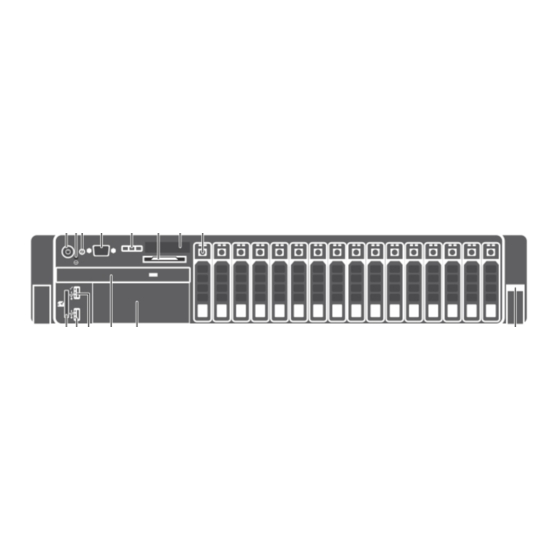
Page 10: Front-Panel Features And Indicators
Front-panel features and indicators Figure 1. Front-panel features and indicators (3.5 inch hard-drive chassis)—PowerEdge R730 Item Indicator, button, or Icon Description connector Power-on indicator, The power-on indicator lights when the system power button power is on. The power button controls the power supply output to the system. - Page 11 Allows you to connect USB devices to the system USB management port/ or provides access to the iDRAC Direct features. For iDRAC Direct more information, see the Integrated Dell Remote Access Controller User’s Guide at dell.com/ esmmanuals. The USB management port is USB 2.0-compliant.
- Page 12 Figure 2. Front-panel features and indicators (2.5 inch hard-drive chassis)—PowerEdge R730 Item Indicator, button, or Icon Description connector Power-on indicator, The power-on indicator lights when the system power button power is on. The power button controls the power supply output to the system.
- Page 13 Allows you to connect USB devices to the system USB management port/ or provides access to the iDRAC Direct features. iDRAC Direct For more information, see the Integrated Dell Remote Access Controller User’s Guide at dell.com/esmmanuals. The USB management port is USB 2.0-compliant.
- Page 14 Figure 3. Front-panel features and indicators (2.5 inch hard-drive chassis)—PowerEdge R730xd Figure 4. Front-panel features and indicators (3.5 inch hard-drive chassis)—PowerEdge R730xd Figure 5. Front-panel features and indicators (3.5 inch and 1.8 inch hard-drive chassis)—PowerEdge R730xd...
- Page 15 Item Indicator, Button, or Icon Description Connector Diagnostic indicators The diagnostic indicators light up to display error status. System identification The identification buttons on the front and back button panels can be used to locate a particular system within a rack. When one of these buttons is pressed, the system status indicator on the back flashes until one of the buttons is pressed again.
-
Page 16: Lcd Panel Features
The LCD panel of your system provides system information and status and error messages to indicate if the system is operating correctly or if the system needs attention. For more information on error messages, see the Dell Event and Error Messages Reference Guide at dell.com/esmmanuals. •... -
Page 17: Home Screen
SEL. This is useful when trying to match an LCD message with an SEL entry. Select Simple to display LCD error messages in a simplified user-friendly description. For more information on error messages, see the Dell Event and Error Messages Reference Guide at dell.com/esmmanuals. Set home Select the default information to be displayed on the LCD Home screen. -
Page 18: View Menu
For more standby, and if any error information on error messages, see the Dell exists (for example, a failed Event and Error Messages Reference Guide at fan or hard drive). - Page 19 Icon Description Condition Corrective action electrical error (for example, a problem with the power supply, check the voltage out of range, or a LED on the power supply. Re-seat the power failed power supply or voltage supply by removing and reinstalling it. If the regulator).
-
Page 20: Hard-Drive Indicator Codes
Hard-drive indicator codes Figure 7. Hard-drive indicators hard-drive activity indicator hard-drive status indicator hard drive Figure 8. Hard-drive indicators on the hard-drive tray backplane hard-drive activity indicator hard-drive status indicator hard-drive backplane on hard-drive tray NOTE: If the hard drive is in Advanced Host Controller Interface (AHCI) mode, the status indicator (on the right side) does not function and remains off. -
Page 21: Idrac Direct Led Indicator Codes
Drive-status indicator pattern (RAID only) Condition Blinks green two times per second Identifying drive or preparing for removal. Drive ready for insertion or removal. NOTE: The drive status indicator remains off until all hard drives are initialized after the system is turned on. -
Page 22: Quick Sync Indicator Codes
Convention iDRAC Direct Condition LED indicator pattern Green and turns Indicates that the file transfer is complete. Not lit Indicates that the USB is ready to be removed or that a task is complete. The table below displays iDRAC Direct activity when configuring iDRAC Direct using your laptop and cable (Laptop Connect). -
Page 23: Back-Panel Features And Indicators
NOTE: For security purposes, Quick Sync turns off after thirty seconds of in-activity after the activation button is pressed. Once timed-out, the user is expected to press the activation button again to activate Quick Sync. Back-panel features and indicators Figure 11. Back-panel features and indicators—PowerEdge R730... - Page 24 Figure 12. Back-panel features and indicators—PowerEdge R730xd Item Indicator, button, or Icon Description connector System identification The identification buttons on the front and back button panels can be used to locate a particular system within a rack. PowerEdge When one of these buttons R730 is pressed, the LCD panel on the front and the system...
- Page 25 The ports are USB 3.0-compliant. Full-height PCIe Allows you to connect up to four full-height PCI expansion-card slot (4) Express expansion cards. (PowerEdge R730) Full-height PCIe Allows you to connect up to three full-height PCI expansion-card slot (3) Express expansion cards.
-
Page 26: Nic Indicator Codes
NIC indicator codes Figure 13. NIC indicators link indicator activity indicator Indicator Indicator code Link and activity indicators are off The NIC is not connected to the network. Link indicator is green The NIC is connected to a valid network at its maximum port speed (1 Gbps or 10 Gbps). - Page 27 Figure 14. AC power supply unit status indicator AC power supply unit status indicator/handle Convention Power indicator Condition pattern Green The handle indicator lights green indicating that a valid power source is connected to the power supply unit and that the power supply unit is operational.
- Page 28 Convention Power indicator Condition pattern CAUTION: When correcting a power supply unit mismatch, replace only the power supply unit with the flashing indicator. Swapping the opposite power supply unit to make a matched pair can result in an error condition and unexpected system shutdown.
-
Page 29: Documentation Matrix
Rack documentation included with your rack solution Set up your system and know the system technical Getting Started With Your System that shipped with specifications your system or see dell.com/poweredgemanuals Install the operating system Operating system documentation at dell.com/ operatingsystemmanuals... -
Page 30: Quick Resource Locator
Use the Quick Resource Locator (QRL) to get immediate access to system information and how-to videos. This can be done by visiting dell.com/QRL or by using your smartphone or tablet and a model specific Quick Resource (QR) code located on your Dell PowerEdge system. To try out the QR code, scan... -
Page 31: Performing Initial System Configuration
Turn on the attached peripherals. Methods of setting up and configuring the iDRAC IP address You can set up the Integrated Dell Remote Access Controller (iDRAC) IP address by using one of the following interfaces: iDRAC Settings utility. Lifecycle Controller. -
Page 32: Information About Logging In To Idrac
For more information, see the Integrated Dell Remote Access Controller User’s Guide at dell.com/esmmanuals. You can also remotely monitor and manage the server, using the Dell OpenManage Server Administrator (OMSA) software and OpenManage Essentials (OME) systems management console. For more information, see dell.com/openmanagemanuals. - Page 33 NOTE: If you do not have the service tag, select Automatically detect my Service Tag for me to allow the system to automatically detect your service tag, or select Choose from a list of all Dell products to select your product from the Product Selection page. Click Get drivers and downloads.
-
Page 34: Pre-Operating System Management Applications
• Dell Lifecycle Controller Dell Lifecycle Controller allows you to perform useful tasks such as configuring BIOS and hardware settings, deploying operating system, updating drivers, changing RAID settings, and saving hardware profiles. For more information about Dell Lifecycle Controller, see the documentation at dell.com/ esmmanuals. -
Page 35: About System Setup
UEFI. You can enable or disable various iDRAC parameters by using the iDRAC Settings utility. For more information about this utility, see the Integrated Dell Remote Access Controller User’s Guide at dell.com/esmmanuals. Device Settings Enables you to configure device settings. -
Page 36: System Information Screen Details
Menu Item Description Processor Settings Displays information and options related to the processor such as speed, cache size, and so on. SATA Settings Displays options to enable or disable the integrated SATA controller and ports. Boot Settings Displays options to specify the boot mode (BIOS or UEFI). Enables you to modify UEFI and BIOS boot settings. -
Page 37: Memory Settings Screen Details
Operating Mode Advanced ECC Mode, Mirror Mode, Spare Mode, Spare with Advanced ECC Mode, and Dell Fault Resilient Mode. By default, the Memory Operating Mode option is set to Optimizer Mode. NOTE: The Memory Operating Mode can have different defaults and available options based on the memory configuration of your system. -
Page 38: Processor Settings Screen Details
Menu Item Description installed. If Disabled, the system supports NUMA (asymmetric) memory configurations. By default, Node Interleaving option is set to Disabled. Snoop Mode Specifies the Snoop Mode options. Snoop Mode options available are Home Snoop, Early Snoop, Cluster on Die. By default, the Snoop Mode option is set to Early Snoop. -
Page 39: Sata Settings Screen Details
TDP refers to the maximum amount of power the cooling system is required to dissipate. X2Apic Mode Enables or disables the X2Apic mode. Dell Controlled NOTE: Depending on the number of installed CPUs, there may be up to four Turbo processor listings. - Page 40 Example Menu Item Description Embedded SATA Enables the embedded SATA to be set to Off, ATA, AHCI, or RAID modes. By default, the Embedded SATA option is set to AHCI. Security Freeze Sends Security Freeze Lock command to the Embedded SATA drives during POST. Lock This option is only applicable to ATA and AHCI mode.
- Page 41 Menu Item Description Drive Type Displays the type of drive attached to the SATA port. Capacity Displays the total capacity of the hard drive. The field is undefined for removable media devices such as optical drives. Port E Sets the drive type of the selected device. For Embedded SATA settings in ATA mode, set this field to Auto to enable BIOS support.
-
Page 42: Boot Settings Screen Details
Menu Item Description Port I Sets the drive type of the selected device. For Embedded SATA settings in ATA mode, set this field to Auto to enable BIOS support. Set it to OFF to turn off BIOS support. For AHCI mode or RAID mode, BIOS always enables support. Model Displays the drive model of the selected device. -
Page 43: Network Settings Screen Details
Menu Item Description list is attempted to boot. When set to Enabled, all hard disk devices are attempted in order, as listed in the Hard-Disk Drive Sequence. This option is not enabled for UEFI Boot Mode. Boot Options Configures the boot sequence and the boot devices. Settings Network Settings screen details You can use the Network Settings screen to modify PXE device settings. - Page 44 Menu Item Description Integrated RAID Enables or disables the integrated RAID controller. By default, the option is set to Controller Enabled. Integrated Enables or disables the integrated network card. Network Card 1 Embedded NIC1 NOTE: The Embedded NIC1 and NIC2 option is only available on systems that and NIC2 do not have Integrated Network Card 1.
-
Page 45: Serial Communication Screen Details
Serial Communication screen details You can use the Serial Communication screen to view the properties of the serial communication port. You can view the Serial Communication screen by clicking System Setup Main Menu → System BIOS → Serial Communication. The Serial Communication screen details are explained below. Example Menu Item Description... - Page 46 Custom, the BIOS automatically sets the rest of the options. You can only change the rest of the options if the mode is set to Custom. By default, the System Profile option is set to Performance Per Watt Optimized (DAPC). DAPC is Dell Active Power Controller.
-
Page 47: System Security Settings Screen Details
Menu Item Description Number of Turbo NOTE: If there are two processors installed in the system, you see an entry for Boot Enabled Number of Turbo Boost Enabled Cores for Processor 2. Cores for Processor 1 Controls the number of turbo boost enabled cores for processor 1. By default, the maximum number of cores is enabled. - Page 48 Menu Item Description Clears all the contents of the TPM. By default, the TPM Clear option is set to No. Intel TXT Enables or disables the Intel Trusted Execution Technology (TXT). To enable Intel TXT, Virtualization Technology must be enabled and TPM Security must be Enabled with Pre-boot measurements.
-
Page 49: Miscellaneous Settings Screen Details
Menu Item Description Authorized Imports, exports, deletes, or restores entries in the Authorized Signature Database Signature (db). Database Forbidden Imports, exports, deletes, or restores entries in the Forbidden Signature Database Signature (dbx). Database Miscellaneous Settings screen details You can use the Miscellaneous Settings screen to perform specific functions such as updating the asset tag, and changing the system date and time. -
Page 50: About Boot Manager
Menu Item Description results can be applied. It takes the system longer to be ready due to the forced system reset. When disabled, ISC does not execute. About Boot Manager Boot Manager enables you to add, delete, and arrange boot options. You can also access System Setup and boot options without restarting the system. -
Page 51: Choosing The System Boot Mode
NOTE: Operating systems must be UEFI-compatible to be installed from the UEFI boot mode. DOS and 32-bit operating systems do not support UEFI and can only be installed from the BIOS boot mode. NOTE: For the latest information on supported operating systems, go to dell.com/ossupport. Assigning a system and setup password Prerequisites NOTE: The password jumper enables or disables the System Password and Setup Password features. -
Page 52: Deleting Or Changing An Existing System And/Or Setup Password
Re-enter the system password, and click OK. Select Setup Password, enter your system password and press <Enter> or <Tab>. A message prompts you to re-enter the setup password. Re-enter the setup password, and click OK. Press <Esc> to return to the System BIOS screen. Press <Esc> again. A message prompts you to save the changes. -
Page 53: Installing And Removing System Components
Damage due to servicing that is not authorized by Dell is not covered by your warranty. Read and follow the safety instructions that came with the product. -
Page 54: Recommended Tools
Recommended tools You need the following tools to perform the removal and installation procedures: • Key to the bezel lock. This is only required when you have a bezel. • #2 Phillips screwdriver • #1 Phillips screwdriver • T6, T8, T10, and T15 Torx screwdrivers The following tools are required for assembling cables for a DC power supply unit (PSU): •... - Page 55 Figure 16. Removing and installing the front bezel bezel lock front bezel Figure 17. Removing and installing the Quick Sync bezel keylock Quick Sync bezel...
-
Page 56: Installing The Front Bezel
Related videos http://www.Dell.com/QRL/Server/PER730/Bezel http://www.Dell.com/QRL/Server/PER730/iDRAC-QuickSync Installing the front bezel Hook the right end of the bezel onto the chassis. Fit the free end of the bezel onto the system. Secure the bezel with the keylock. Removing the system cover Prerequisites Ensure that you read the Safety instructions. -
Page 57: Installing The System Cover
Figure 18. Removing and installing the system cover system cover latch latch release lock Related video http://www.Dell.com/QRL/Server/PER730/Cover Installing the system cover Prerequisites Ensure that you read the Safety instructions. Steps Align the slots of the system cover with the tabs on the chassis. -
Page 58: Inside The System
Damage due to servicing that is not authorized by Dell is not covered by your warranty. Read and follow the safety instructions that came with the product. -
Page 59: Cooling Shroud
expansion-card riser 3 network daughter card expansion-card riser 2 expansion-card riser 1 hard-drive backplane Figure 20. Inside the system—PowerEdge R730xd cooling-fan in the cooling-fan assembly (6) processor (2) DIMMs (24) internal USB port hard-drive backplane (back) vFlash media slot hard drive (2) (back) power supply unit (2) expansion-card riser 3 network daughter card... -
Page 60: Removing The Cooling Shroud
Damage due to servicing that is not authorized by Dell is not covered by your warranty. Read and follow the safety instructions that came with the product. -
Page 61: Installing The Cooling Shroud
Damage due to servicing that is not authorized by Dell is not covered by your warranty. Read and follow the safety instructions that came with the product. -
Page 62: Installing The Hard-Drive Tray
Damage due to servicing that is not authorized by Dell is not covered by your warranty. Read and follow the safety instructions that came with the product. -
Page 63: Removing A Hard-Drive Blank From A Hard-Drive Carrier
Damage due to servicing that is not authorized by Dell is not covered by your warranty. Read and follow the safety instructions that came with the product. -
Page 64: Installing A Hard-Drive Blank Into A Hard-Drive Carrier
Damage due to servicing that is not authorized by Dell is not covered by your warranty. Read and follow the safety instructions that came with the product. -
Page 65: Removing A Hard-Drive Carrier From The Hard-Drive Tray
Damage due to servicing that is not authorized by Dell is not covered by your warranty. Read and follow the safety instructions that came with the product. -
Page 66: Installing A Hard-Drive Carrier Into The Hard-Drive Tray
Damage due to servicing that is not authorized by Dell is not covered by your warranty. Read and follow the safety instructions that came with the product. -
Page 67: Removing A Hard Drive From A Hard-Drive Carrier
Damage due to servicing that is not authorized by Dell is not covered by your warranty. Read and follow the safety instructions that came with the product. -
Page 68: Installing A Hard Drive Into A Hard-Drive Carrier
Damage due to servicing that is not authorized by Dell is not covered by your warranty. Read and follow the safety instructions that came with the product. -
Page 69: Installing The Hard-Drive Backplane In The Hard-Drive Tray
Damage due to servicing that is not authorized by Dell is not covered by your warranty. Read and follow the safety instructions that came with the product. -
Page 70: Cooling Fans
Damage due to servicing that is not authorized by Dell is not covered by your warranty. Read and follow the safety instructions that came with the product. -
Page 71: Installing A Cooling Fan
(6) fan release tab (6) cooling fan (6) cooling-fan connector on system board Related video http://www.Dell.com/QRL/Server/PER730/Fans Next steps Replace the cooling fan. See Installing a cooling fan. Follow the procedure listed in After working inside your system. -
Page 72: Cooling-Fan Assembly
Damage due to servicing that is not authorized by Dell is not covered by your warranty. Read and follow the safety instructions that came with the product. - Page 73 (6) release lever (2) guide pin on the system board (2) cooling-fan connector (6) guide pin on the chassis (6) Related video http://www.Dell.com/QRL/Server/PER730/Fans Next steps Replace the cooling-fan assembly. See Installing the cooling-fan assembly. Follow the procedure listed in After working inside your system.
-
Page 74: Installing The Cooling-Fan Assembly
Damage due to servicing that is not authorized by Dell is not covered by your warranty. Read and follow the safety instructions that came with the product. - Page 75 Figure 29. Memory socket locations Memory channels are organized as follows: Processor 1 channel 0: slots A1, A5, and A9 channel 1: slots A2, A6, and A10 channel 2: slots A3, A7, and A11 channel 3: slots A4, A8, and A12 Processor 2 channel 0: slots B1, B5, and B9 channel 1: slots B2, B6, and B10...
-
Page 76: General Memory Module Installation Guidelines
channel 3: slots B4, B8, and B12 The following table shows the memory populations and operating frequencies for the supported configurations. DIMM Type DIMMs Populated/ Operating Frequency (in Maximum DIMM Rank/Channel Channel MT/s) 1.2 V RDIMM 2133, 1866, 1600, 1333 Dual rank or single rank 2133, 1866, 1600, 1333 Dual rank or single rank... -
Page 77: Memory Mirroring
NOTE: You can mix x4 and x8 DRAM based DIMMs to support RAS features. However, all guidelines for specific RAS features must be followed. x4 DRAM based DIMMs retain Single Device Data Correction (SDDC) in memory optimized (independent channel) mode. x8 DRAM based DIMMs require Advanced ECC mode to gain SDDC. -
Page 78: Sample Memory Configurations
Sample memory configurations The following tables show sample memory configurations for one and two processor configurations that follow the appropriate memory guidelines. NOTE: 1R, 2R, and 4R in the following tables indicate single-, dual-, and quad-rank DIMMs respectively. Table 1. Memory configurations—single processor System DIMM size Number of... - Page 79 System DIMM size Number of DIMM rank, DIMM slot population capacity (in (in GB) DIMMs organization, and frequency 2R, x4 and 2R, x8, 1600 NOTE: 16 GB DIMMs must MT/s be installed in slots numbered A1, A2, A3, A4, A5, A6, A7, and A8 and 8 GB DIMMs must be installed in slots A9 and A11.
-
Page 80: Removing Memory Modules
Damage due to servicing that is not authorized by Dell is not covered by your warranty. Read and follow the safety instructions that came with the product. - Page 81 To release the memory module from the socket, simultaneously press the ejectors on both ends of the memory-module socket. Figure 30. Removing and installing a memory module memory-module memory-module socket memory module socket ejector (2) Related video http://www.Dell.com/QRL/Server/PER730/DIMMs...
-
Page 82: Installing Memory Modules
Damage due to servicing that is not authorized by Dell is not covered by your warranty. Read and follow the safety instructions that came with the product. -
Page 83: Processors
Figure 31. Installing the memory module memory module alignment key memory-module socket ejector (2) When the memory module is properly seated in the socket, the levers on the memory module socket align with the levers on the other sockets that have memory modules installed. Repeat steps 4 and 5 of this procedure to install the remaining memory modules. -
Page 84: Removing A Processor
Damage due to servicing that is not authorized by Dell is not covered by your warranty. Read and follow the safety instructions that came with the product. - Page 85 Figure 32. Removing and installing a processor heat sink 1. captive screw (4) 2. heat sink 3. processor socket 4. slot (4) CAUTION: The processor is held in its socket under strong pressure. Be aware that the release lever can spring up suddenly if not firmly grasped.
- Page 86 Figure 33. Processor shield 1. close first socket release lever 2. lock icon 3. processor 4. open first socket release lever 5. unlock icon To remove the processor: a. Release the open first socket-lever near the unlock icon by pushing the lever down and out from under the tab.
- Page 87 Figure 34. Removing and installing a processor 1. close first socket-release lever 2. pin-1 indicator of processor 3. processor 4. slot (4) 5. processor shield 6. open first socket-release lever 7. socket 8. socket keys (4) d. Hold the tab on the processor shield and lift the processor shield until the open first socket- release lever lifts up.
-
Page 88: Installing A Processor
Damage due to servicing that is not authorized by Dell is not covered by your warranty. Read and follow the safety instructions that came with the product. - Page 89 CAUTION: Do not use force to seat the processor. When the processor is positioned correctly, it engages easily into the socket. b. Align the pin-1 indicator of the processor with the triangle on the socket. c. Place the processor on the socket such that the slots on the processor align with the socket keys. CAUTION: Do not use force to seat the processor.
-
Page 90: Pcie Card Holder
Damage due to servicing that is not authorized by Dell is not covered by your warranty. Read and follow the safety instructions that came with the product. -
Page 91: Installing The Pcie Card Holder
Damage due to servicing that is not authorized by Dell is not covered by your warranty. Read and follow the safety instructions that came with the product. -
Page 92: Opening And Closing The Pcie Card Holder Latch
Damage due to servicing that is not authorized by Dell is not covered by your warranty. Read and follow the safety instructions that came with the product. -
Page 93: Cable Retention Bracket
Damage due to servicing that is not authorized by Dell is not covered by your warranty. Read and follow the safety instructions that came with the product. -
Page 94: Installing The Cable Retention Bracket
Damage due to servicing that is not authorized by Dell is not covered by your warranty. Read and follow the safety instructions that came with the product. - Page 95 Steps Loosen the screws that secure the integrated storage controller cable to the integrated storage- controller card connector on the system board. Lift the integrated storage controller cable out. Lift one end of the card and angle it to disengage the card from the integrated storage-controller card holder on system board.
-
Page 96: Installing The Integrated Storage Controller Card
Damage due to servicing that is not authorized by Dell is not covered by your warranty. Read and follow the safety instructions that came with the product. - Page 97 Riser PCIe slot Processor Height Length Link width Slot width connection Processor 2 Low Profile Half Length Processor 2 Full Height Full Length Processor 1 Full Height Full Length 3 (default) Processor 1 Full Height Full Length 3 (alternate) Processor 1 Full Height Full Length 3 (default)
-
Page 98: Removing An Expansion Card From Expansion-Card Riser 2 Or 3
Damage due to servicing that is not authorized by Dell is not covered by your warranty. Read and follow the safety instructions that came with the product. -
Page 99: Installing An Expansion Card Into The Expansion-Card Riser 2 Or 3
Damage due to servicing that is not authorized by Dell is not covered by your warranty. Read and follow the safety instructions that came with the product. -
Page 100: Removing An Expansion Card From The Expansion-Card Riser 1
Damage due to servicing that is not authorized by Dell is not covered by your warranty. Read and follow the safety instructions that came with the product. -
Page 101: Installing An Expansion Card Into The Expansion-Card Riser 1
Damage due to servicing that is not authorized by Dell is not covered by your warranty. Read and follow the safety instructions that came with the product. -
Page 102: Removing The Riser 1 Blank
Damage due to servicing that is not authorized by Dell is not covered by your warranty. Read and follow the safety instructions that came with the product. -
Page 103: Installing The Riser 1 Blank
Damage due to servicing that is not authorized by Dell is not covered by your warranty. Read and follow the safety instructions that came with the product. - Page 104 Steps Holding the slots on the expansion-card riser, lift the riser from the riser connector on the system board. NOTE: To remove expansion-card risers 2 and 3, hold the edges of the expansion-card riser. NOTE: To ensure proper system cooling, the riser 1 blank must be installed in the riser 1 slot. Remove the riser 1 blank only if you are installing riser 1.
- Page 105 Figure 44. Identifying connectors on the expansion card riser 1 expansion-card slot 1 expansion-card slot 2 expansion-card slot 3...
- Page 106 Figure 45. Removing and installing the expansion card riser 2 power connector (for GPU cards) expansion-card riser 2 riser guide-back expansion-card riser 2 connector riser guide-front...
- Page 107 Figure 46. Identifying connectors on the expansion card riser 2 expansion-card slot 4 expansion-card slot 5 power connector (for GPU cards)
- Page 108 Figure 47. Removing and installing the expansion card riser 3 riser guide-front power connector (for GPU cards) expansion-card riser 3 riser guide-back expansion-card riser 3 connector...
- Page 109 Figure 48. Identifying connectors on the expansion card riser 3 (default) expansion-card slot 6 expansion-card slot 7 power connector (for GPU cards) Figure 49. Identifying connectors on the expansion card riser 3 (alternate) expansion-card slot 6 power connector (for GPU cards) Next steps If applicable, remove or install an expansion card on the riser.
-
Page 110: Installing Expansion-Card Risers
Damage due to servicing that is not authorized by Dell is not covered by your warranty. Read and follow the safety instructions that came with the product. -
Page 111: Removing A Gpu Card
Damage due to servicing that is not authorized by Dell is not covered by your warranty. Read and follow the safety instructions that came with the product. -
Page 112: Installing A Gpu Card
Damage due to servicing that is not authorized by Dell is not covered by your warranty. Read and follow the safety instructions that came with the product. -
Page 113: Internal Dual Sd Module (Optional)
Damage due to servicing that is not authorized by Dell is not covered by your warranty. Read and follow the safety instructions that came with the product. -
Page 114: Removing The Internal Dual Sd Module
Damage due to servicing that is not authorized by Dell is not covered by your warranty. Read and follow the safety instructions that came with the product. - Page 115 Figure 51. Removing and installing the Internal Dual SD Module (IDSDM) Internal Dual SD module LED status indicator (2) SD card (2) SD card slot 2 SD card slot 1 IDSDM connector The following table describes the IDSDM indicator codes. Convention IDSDM indicator code Condition...
-
Page 116: Installing The Internal Dual Sd Module
Damage due to servicing that is not authorized by Dell is not covered by your warranty. Read and follow the safety instructions that came with the product. - Page 117 Steps Using a #1 Phillips screwdriver, loosen the captive screws that secure the network daughter card to the system board. Hold the network daughter card by the edges on either side of the touch point and lift the card to remove it from the connector on the system board.
-
Page 118: Installing The Network Daughter Card
Damage due to servicing that is not authorized by Dell is not covered by your warranty. Read and follow the safety instructions that came with the product. -
Page 119: System Battery
Steps Locate the USB connector or USB key on the system board. NOTE: To locate the internal USB connector on the system board, see System board connectors If installed, remove the USB key. Insert the new USB key into the USB connector. Figure 53. - Page 120 Damage due to servicing that is not authorized by Dell is not covered by your warranty. Read and follow the safety instructions that came with the product.
-
Page 121: Power Supply Units
Figure 55. Installing the system battery system battery positive side of the battery connector Next steps Install the cooling shroud. Follow the procedure listed in After working inside your system. While booting, press <F2> to enter the System Setup and ensure the battery is operating properly. Enter the correct time and date in the System Setup Time and Date fields. -
Page 122: Hot Spare Feature
You can configure the Hot Spare feature using the iDRAC settings. For more information on iDRAC settings, see the Integrated Dell Remote Access Controller User’s Guide at dell.com/support/manuals. Removing the power supply unit blank If you are installing a second power supply unit, remove the power supply unit blank in the bay by pulling the blank outward. -
Page 123: Installing The Power Supply Unit Blank
Damage due to servicing that is not authorized by Dell is not covered by your warranty. Read and follow the safety instructions that came with the product. -
Page 124: Installing An Ac Power Supply Unit
Damage due to servicing that is not authorized by Dell is not covered by your warranty. Read and follow the safety instructions that came with the product. -
Page 125: Wiring Instructions For A Dc Power Supply Unit
All electrical wiring must comply with applicable local or national codes and practices. Damage due to servicing that is not authorized by Dell is not covered by your warranty. Read and follow all safety instructions that came with the product. - Page 126 All electrical wiring must comply with applicable local or national codes and practices. Damage due to servicing that is not authorized by Dell is not covered by your warranty. Read and follow all safety instructions that came with the product.
- Page 127 All electrical wiring must comply with applicable local or national codes and practices. Damage due to servicing that is not authorized by Dell is not covered by your warranty. Read and follow all safety instructions that came with the product.
-
Page 128: Removing A Dc Power Supply Unit
All electrical wiring must comply with applicable local or national codes and practices. Damage due to servicing that is not authorized by Dell is not covered by your warranty. Read and follow all safety instructions that came with the product. -
Page 129: Installing A Dc Power Supply Unit
All electrical wiring must comply with applicable local or national codes and practices. Damage due to servicing that is not authorized by Dell is not covered by your warranty. Read and follow all safety instructions that came with the product. - Page 130 Follow the procedure listed in Before working inside your system. Remove the following: cooling shroud cooling-fan assembly hard-drive tray (if installed) power supply unit(s) all expansion-card risers integrated storage controller card internal dual SD module internal USB key (if installed) PCIe card holder cable retention bracket heat sink(s)/heat-sink blank(s)
-
Page 131: Installing The System Board
Figure 61. Removing and installing the system board release pin system board system-board holder Next steps Replace the system board. See, Installing the system board. Follow the procedure listed in After working inside your system. Installing the system board Prerequisites Ensure that you read the Safety instructions. - Page 132 Damage due to servicing that is not authorized by Dell is not covered by your warranty. Read and follow the safety instructions that came with the product.
-
Page 133: Trusted Platform Module
If the service tag is not backed up in the backup flash device, enter the system service tag manually. For more information, see Entering the system service tag. Update the BIOS and iDRAC versions. Re-enable the Trusted Platform Module (TPM). For more information, see Re-enabling the TPM for TXT users. -
Page 134: Re-Enabling The Tpm For Bitlocker Users
CAUTION: Do not remove an installed Trusted Platform Module (TPM). Any attempt to remove an installed TPM from the system board may damage the TPM. Steps Align the edge connectors on the TPM with the slot on the TPM connector. Insert the TPM into the TPM connector such that the plastic bolt aligns with the slot on the system board. -
Page 135: Hard Drives
Damage due to servicing that is not authorized by Dell is not covered by your warranty. Read and follow the safety instructions that came with the product. -
Page 136: Installing A 2.5 Inch Hard-Drive Blank
Damage due to servicing that is not authorized by Dell is not covered by your warranty. Read and follow the safety instructions that came with the product. -
Page 137: Installing A 2.5 Inch Hard-Drive Blank (Back)
Figure 64. Removing and installing a 2.5 inch hard-drive blank (back) hard-drive blank (back) Installing a 2.5 inch hard-drive blank (back) Prerequisites Ensure that you read the Safety instructions. If installed, remove the front bezel. NOTE: This procedure applies only to PowerEdge R730xd systems. Steps Insert the hard-drive blank into the hard-drive slot until it clicks into place. -
Page 138: Installing A 1.8 Inch Hard-Drive Blank
Damage due to servicing that is not authorized by Dell is not covered by your warranty. Read and follow the safety instructions that came with the product. -
Page 139: Installing A 3.5 Inch Hard-Drive Blank
Steps Press the release button and slide the blank out of the hard-drive slot. Figure 66. Removing and installing a 3.5 inch hard-drive blank hard-drive blank release button Next steps If applicable, install the front bezel. Installing a 3.5 inch hard-drive blank Prerequisites Ensure that you read the Safety... -
Page 140: Installing A 1.8 Inch Hard Drive Into A Hard-Drive Carrier
Damage due to servicing that is not authorized by Dell is not covered by your warranty. Read and follow the safety instructions that came with the product. - Page 141 If the hard drive is online, the green activity/fault indicator flashes as the drive is turned off. When the hard-drive indicators are off, the hard drive is ready for removal. CAUTION: To prevent data loss, ensure that your operating system supports hot-swap drive installation.
-
Page 142: Installing A Hot-Swap Hard Drive
Damage due to servicing that is not authorized by Dell is not covered by your warranty. Read and follow the safety instructions that came with the product. -
Page 143: Removing A Hard Drive From A Hard-Drive Carrier
Remove the screws from the slide rails on the hard-drive carrier. Lift the hard drive out of the hard-drive carrier. Figure 70. Removing and installing a hard drive into a hard-drive carrier screw (4) hard drive hard-drive carrier Related video http://www.Dell.com/QRL/Server/PER730/HDD... -
Page 144: Installing A Hard Drive Into A Hard-Drive Carrier
Damage due to servicing that is not authorized by Dell is not covered by your warranty. Read and follow the safety instructions that came with the product. -
Page 145: Removing The Hard-Drive Backplane (R730)
Damage due to servicing that is not authorized by Dell is not covered by your warranty. Read and follow the safety instructions that came with the product. - Page 146 (2) SAS cable (2) mini SAS connector (2) hard-drive connector (16) Figure 72. Cabling diagram—2.5 inch (x16) SAS/SATA backplane—PowerEdge R730 hard drive backplane expander hard drive backplane backplane signal connector 1 system board integrated storage controller card...
- Page 147 Figure 73. Removing and installing the 2.5 inch (x8) SAS/SATA backplane—PowerEdge R730 hard-drive connector (8) hard-drive backplane release tab backplane power cable SAS cable (2) backplane signal cable mini SAS connector (2)
- Page 148 Figure 74. Cabling diagram—2.5 inch (x8) SAS/SATA backplane—PowerEdge R730 (option 1) hard-drive backplane backplane signal connector 1 system board integrated storage controller card...
- Page 149 Figure 75. Cabling diagram—2.5 inch (x8) SAS/SATA backplane—PowerEdge R730 (option 2) hard-drive backplane backplane signal connector 1 system board SAS A connector on the system board SAS B connector on the system board...
- Page 150 Figure 76. Removing and installing the 3.5 inch (x8) SAS/SATA backplane—PowerEdge R730 release tab (2) SAS cable (2) backplane signal connector backplane power cable mini SAS cable connector hard-drive backplane hard-drive connector (8)
- Page 151 Figure 77. Cabling diagram—3.5 inch (x8) SAS/SATA backplane—PowerEdge R730 (option 1) hard-drive backplane backplane signal connector 1 system board integrated storage controller card...
-
Page 152: Removing The Hard-Drive Backplane (R730Xd)
Figure 78. Cabling diagram—3.5 inch (x8) SAS/SATA backplane—PowerEdge R730 (option 2) hard-drive backplane backplane signal connector 1 system board SAS A connector on the system board SAS B connector on the system board Next steps Replace the hard-drive backplane. See Installing the hard-drive backplane (R730 and R730xd). - Page 153 Damage due to servicing that is not authorized by Dell is not covered by your warranty. Read and follow the safety instructions that came with the product.
- Page 154 Figure 79. Removing and installing the 2.5 inch (x24) SAS/SATA backplane—PowerEdge R730xd release tab (2) left ear control panel cable backplane power cable hard-drive backplane expander backplane signal cable hard-drive backplane assembly backplane power cable mini SAS cable connector (2) SAS cable (3) 10.
- Page 155 Figure 80. Cabling diagram—2.5 Inch (x24) SAS/SATA backplane—PowerEdge R730xd (option 1) hard-drive backplane expander backplane signal connector 0 backplane signal connector 1 system board integrated storage controller card hard-drive backplane...
- Page 156 Figure 81. Cabling diagram—2.5 Inch (x24) SAS/SATA backplane—PowerEdge R730xd (option 2) hard-drive backplane expander hard-drive backplane backplane signal connector 1 system board integrated storage controller card SAS A1 connector SAS B1 connector...
- Page 157 Figure 82. Cabling diagram—2.5 Inch (x24) SAS/SATA backplane—PowerEdge R730xd (option 3) hard-drive backplane expander hard-drive backplane system board backplane signal connector 0 backplane signal connector 1 SSD/PCIe SSD controller card integrated storage controller card...
- Page 158 Figure 83. Removing and installing the 3.5 inch (x12) SAS/SATA backplane—PowerEdge R730xd release tab (2) SAS cable A2 SAS cable A1 left ear control panel cable backplane signal cable backplane power cable (2) SAS cable A0/B0 USB cable control panel cable 10.
- Page 159 Figure 84. Cabling diagram—3.5 inch (x12) SAS/SATA backplane—PowerEdge R730xd (option 1) hard-drive backplane system board backplane signal connector 0 backplane signal connector 1 integrated storage controller card...
- Page 160 Figure 85. Cabling diagram—3.5 inch (x12) SAS/SATA backplane—PowerEdge R730xd (option 2) hard-drive backplane system board backplane signal connector 0 backplane signal connector 1 hard-drive mid plane integrated storage controller card backplane signal connector 2...
- Page 161 Figure 86. Removing and installing the 1.8 Inch (x18) SAS/SATA backplane—PowerEdge R730xd release pin left ear control panel cable SAS A2 cable backplane signal cable control panel cable backplane power cable USB cable mini SAS connector (2) SAS cable (2) 10.
- Page 162 Figure 87. Cabling diagram—1.8 Inch (x18) SAS/SATA backplane—PowerEdge R730xd hard-drive backplane expander system board backplane signal connector 0 backplane signal connector 1 integrated storage controller card hard-drive backplane Next steps Replace the hard-drive backplane. See Installing the hard-drive backplane (R730 and R730xd).
-
Page 163: Installing The Hard-Drive Backplane (R730 And R730Xd)
Damage due to servicing that is not authorized by Dell is not covered by your warranty. Read and follow the safety instructions that came with the product. -
Page 164: Installing The Optional Hard-Drive Backplane (Back)
Damage due to servicing that is not authorized by Dell is not covered by your warranty. Read and follow the safety instructions that came with the product. -
Page 165: Tape Backup Unit (Optional)
Follow the procedure listed in After working inside your system. Tape backup unit (optional) The tape backup unit is supported only on 2.5 inch hard-drive systems of PowerEdge R730. Removing the tape backup unit Prerequisites Ensure that you read the Safety instructions. -
Page 166: Installing The Tape Backup Unit
Damage due to servicing that is not authorized by Dell is not covered by your warranty. Read and follow the safety instructions that came with the product. -
Page 167: Optical Drive (Optional)
Damage due to servicing that is not authorized by Dell is not covered by your warranty. Read and follow the safety instructions that came with the product. -
Page 168: Installing The Optical Drive
Locate the SD vFlash media slot on the system. For PowerEdge R730 systems the SD vFlash media card is located on the front panel of the system and for PowerEdge R730xd systems it is located on the back panel of the system. -
Page 169: Removing The Vflash Media Unit
Damage due to servicing that is not authorized by Dell is not covered by your warranty. Read and follow the safety instructions that came with the product. -
Page 170: Installing The Vflash Media Unit
Damage due to servicing that is not authorized by Dell is not covered by your warranty. Read and follow the safety instructions that came with the product. -
Page 171: Control Panel Assembly
Damage due to servicing that is not authorized by Dell is not covered by your warranty. Read and follow the safety instructions that came with the product. - Page 172 Figure 93. Removing and installing the control panel—3.5 inch hard drive system—PowerEdge R730 control panel control-panel board control-panel connector cable USB connector cable screw vFlash media connector cable...
- Page 173 Figure 94. Removing and installing the control panel—2.5 inch hard-drive system—PowerEdge R730 control panel control-panel board control-panel connector cable USB connector cable screw (2) vFlash media connector cable Locate and press the tabs on the information tag. Push the information tag out of the slot to remove it from the control panel.
-
Page 174: Installing The Control Panel (R730)
Damage due to servicing that is not authorized by Dell is not covered by your warranty. Read and follow the safety instructions that came with the product. -
Page 175: Removing The Control Panel (R730Xd)
Damage due to servicing that is not authorized by Dell is not covered by your warranty. Read and follow the safety instructions that came with the product. -
Page 176: Installing The Control Panel (R730Xd)
Damage due to servicing that is not authorized by Dell is not covered by your warranty. Read and follow the safety instructions that came with the product. -
Page 177: Removing The I/O Panel (R730Xd)
Damage due to servicing that is not authorized by Dell is not covered by your warranty. Read and follow the safety instructions that came with the product. -
Page 178: Installing The I/O Panel (R730Xd)
Damage due to servicing that is not authorized by Dell is not covered by your warranty. Read and follow the safety instructions that came with the product. - Page 179 Steps Fold the PPID label around the cable. Push the cable until the cable passes completely through the channel. CAUTION: To prevent damage to the I/O cable, you must release the locking tab before removing or installing the I/O cable from the connector on the hard-drive backplane. If locked, rotate the locking tab on the I/O cable connector clockwise 90 degrees to release the lock.
-
Page 180: Troubleshooting Your System
Damage due to servicing that is not authorized by Dell is not covered by your warranty. Read and follow the safety instructions that came with the product. -
Page 181: Troubleshooting Idrac Direct (Usb Xml Configuration)
Getting Help. Troubleshooting iDRAC Direct (USB XML configuration) For information on USB storage device and server configuration, see the Integrated Dell Remote Access Controller User's Guide at dell.com/esmanuals. Steps Ensure your USB storage device is connect to the front USB Management Port, identified by icon. -
Page 182: Troubleshooting Idrac Direct (Laptop Connection)
Troubleshooting iDRAC Direct (laptop connection) For information on USB laptop connection and server configuration, see the Integrated Dell Remote Access Controller User's Guide at dell.com/esmanuals. Steps Make sure your laptop is connected to the front USB Management Port, identified by icon with a USB Type A/A cable. -
Page 183: Troubleshooting A Wet System
Damage due to servicing that is not authorized by Dell is not covered by your warranty. Read and follow the safety instructions that came with the product. -
Page 184: Troubleshooting A Damaged System
Damage due to servicing that is not authorized by Dell is not covered by your warranty. Read and follow the safety instructions that came with the product. -
Page 185: Troubleshooting Power Supply Units
Damage due to servicing that is not authorized by Dell is not covered by your warranty. Read and follow the safety instructions that came with the product. -
Page 186: Troubleshooting Cooling Problems
Damage due to servicing that is not authorized by Dell is not covered by your warranty. Read and follow the safety instructions that came with the product. -
Page 187: Troubleshooting System Memory
Damage due to servicing that is not authorized by Dell is not covered by your warranty. Read and follow the safety instructions that came with the product. -
Page 188: Troubleshooting An Internal Usb Key
Damage due to servicing that is not authorized by Dell is not covered by your warranty. Read and follow the safety instructions that came with the product. -
Page 189: Troubleshooting An Optical Drive
Damage due to servicing that is not authorized by Dell is not covered by your warranty. Read and follow the safety instructions that came with the product. -
Page 190: Troubleshooting A Hard Drive
Damage due to servicing that is not authorized by Dell is not covered by your warranty. Read and follow the safety instructions that came with the product. -
Page 191: Troubleshooting A Storage Controller
Damage due to servicing that is not authorized by Dell is not covered by your warranty. Read and follow the safety instructions that came with the product. -
Page 192: Troubleshooting Processors
Damage due to servicing that is not authorized by Dell is not covered by your warranty. Read and follow the safety instructions that came with the product. -
Page 193: System Messages
System messages For a list of event and error messages generated by the system firmware and agents that monitor system components, see the Dell Event and Error Messages Reference Guide at dell.com/esmmanuals. Warning messages A warning message alerts you to a possible problem and prompts you to respond before the system continues a task. -
Page 194: Using System Diagnostics
Using system diagnostics If you experience a problem with your system, run the system diagnostics before contacting Dell for technical assistance. The purpose of running system diagnostics is to test your system hardware without requiring additional equipment or risking data loss. If you are unable to fix the problem yourself, service and support personnel can use the diagnostics results to help you solve the problem. -
Page 195: System Diagnostic Controls
Displays a time-stamped log of the results of all tests run on the system. This is displayed if at least one event description is recorded. For information about embedded system diagnostics, see the ePSA Diagnostics Guide (Notebooks, Desktops and Servers) at dell.com/support/manuals. -
Page 196: Jumpers And Connectors
Jumpers and connectors System board jumper settings For information on resetting the password jumper to disable a password, see Disabling a forgotten password. Table 5. System board jumper settings Jumper Setting Description PWRD_EN The password reset feature is enabled (pins 2–4). BIOS local access is unlocked at the next AC power cycle. -
Page 197: System Board Connectors
System board connectors Figure 98. System board jumpers and connectors Item Connector Description J_BP_SIG1 Backplane signal connector 1 J_PS_2 PSU 2 connector J_BP_SIG0 Backplane signal connector 0 J_BP0 Backplane power connector 0 J_SATA_CD Optical drive SATA connector J_SATA_TBU Tape backup unit SATA connector J_TBU Tape backup unit power connector J_PS_1... - Page 198 Item Connector Description J_USB USB connector J_VIDEO_REAR Video connector J_COM1 Serial connector J_IDRAC_RJ45 iDRAC8 connector J_CYC System identification connector CYC_ID System identification button J_TPM_MODULE Trusted Platform Module connector J_RISER_2AX Riser 3 connector J_RISER_1AX Riser 1 connector J_RISER_2BX Riser 2 connector J_RISER_1BX Riser 1 connector J_RISER_3AX...
-
Page 199: Disabling A Forgotten Password
Damage due to servicing that is not authorized by Dell is not covered by your warranty. Read and follow the safety instructions that came with the product. -
Page 200: Technical Specifications
Technical specifications Processor Processor type One or two Intel Xeon processor E5-2600 v3 product family Power AC power supply (per power supply) Wattage 495 W, 750 W, or 1100 W 1908 BTU/hr maximum (495 W power supply) Heat dissipation NOTE: Heat dissipation is calculated using 2891 BTU/hr maximum (750 W power supply) the power supply wattage rating. - Page 201 Up to 768 GB with a dual processor Up to 384 GB with a single processor Drives Hard drives (PowerEdge R730) Eight–hard-drive systems Up to eight 3.5 inch or 2.5 inch, internal, hot-swappable SAS, SATA, or Nearline SAS hard drives in hard-drive slots 0 through 7.
- Page 202 Up to twenty 2.5 inch, internal, hot-swappable SAS, SATA, SAS/SATA SSD, or Nearline SAS drives in hard-drive slots 0 through 19, and up to four 2.5 inch Dell PowerEdge Express Flash devices (PCIe SSDs) in slots 20 to 23 and two optional 2.5 inch back-accessible SAS, SATA, SAS/SATA SSD or...
- Page 203 Connectors NOTE: The card slot is available for use only if the iDRAC8 Enterprise license is installed on your system. Front One 4-pin, USB 2.0-compliant (PowerEdge R730) One 4-pin, USB 2.0-compliant (PowerEdge R730xd) One USB management port/iDRAC Direct Video 15-pin VGA...
- Page 204 21 kg (46.29 lb) (3.5 inch plus 1.8 inch hard drive systems) Environmental specifications NOTE: For additional information about environmental measurements for specific system configurations, see dell.com/environmental_datasheets. Temperature Storage –40°C to 65°C (–40°F to 149°F) Continuous operation (for altitude less than 950 10°C to 35°C (50°F to 95°F) with no direct...
- Page 205 Environmental specifications Maximum altitude 3048 m (10,000 ft). Operating Storage 12,000 m (39,370 ft). Operating temperature de-rating Up to 35 °C (95 °F) Maximum temperature is reduced by 1°C/300 m (1°F/547 ft) above 950 m (3,117 ft). 35 °C to 40 °C (95 °F to 104 °F) Maximum temperature is reduced by 1°C/175 m (1°F/319 ft) above 950 m (3,117 ft).
- Page 206 • Tape Backup Unit (TBU) is not supported. • Redundant power supplies are required. • Non Dell qualified peripheral cards and/or peripheral cards greater than 25 W are not supported. • PCIe SSD and GPU is not supported. NOTE: The following additional restrictions apply to PowerEdge R730xd.
-
Page 207: Getting Help
Documentation feedback If you have feedback for this document, write to documentation_feedback@dell.com. Alternatively, you can click on the Feedback link in any of the Dell documentation pages, fill out the form, and click Submit to send your feedback. Quick Resource Locator Use the Quick Resource Locator (QRL) to get immediate access to system information and how-to videos. - Page 208 Quick Resource (QR) code located on your Dell PowerEdge system. To try out the QR code, scan the following image.