
Related Manuals for ABB Industrial IT enabled 2600T Series


Summary of Contents for ABB Industrial IT enabled 2600T Series
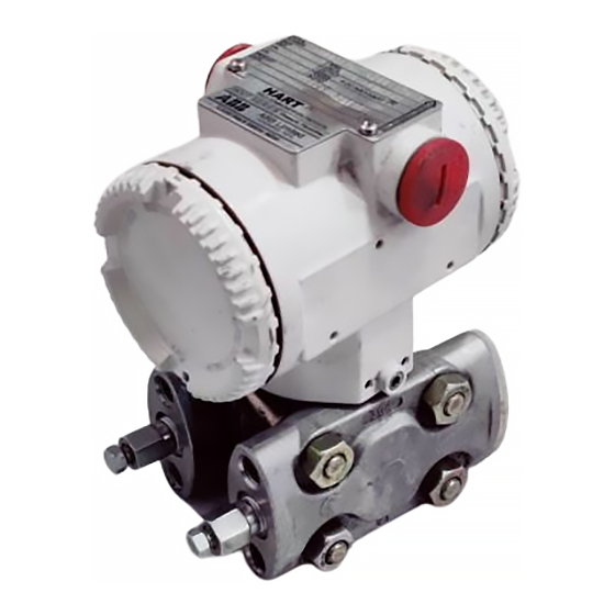
- Page 1 Field Operating instruction IM/262_4D_7 2600T Series Pressure Transmitters Models 262B/D/V/P Models 264B/D/V/P - 1 -...
- Page 2 Cert. No. Q5907 As a part of ABB, a world leader in process automation technology, we offer customers application expertise, service and support worldwide. ISO 9001: 2000 We are committed to teamwork, high quality manufacturing, advanced technology and unrivalled service and support.
-
Page 3: Table Of Contents
CONTENTS INTRODUCTION Section Page The 2600T series is a modular range of field mounted, micro- processor based electronic transmitters, using a unique inductive sensing element. Accurate and reliable INTRODUCTION ............3 measurement of differential pressure, gauge and absolute TRANSPORT, STORAGE, HANDLING AND pressure, flow and liquid level is provided, in the even most PRODUCT IDENTIFICATION ........ -
Page 4: Product Identification
TRANSPORT PRODUCT IDENTIFICATION The instrument is identified by the data plates shown in After final calibration, the instrument is packed in a carton Figure 1. (Type 2 to ANSI/ASME N45.2.2-1978), intended to provide The Nameplate (ref.A) provides information concerning the protection from physical damage. -
Page 5: Principle Of Operation
PRINCIPLE OF OPERATION While maintaining the modular construction, it may be adopted MODELS: 262/264 D-V-P a sensor module different then the inductive one. The sensor can be piezoresistive. The completely welded sensor module Primary Electronics is a twin-chamber system with an integral overload diaphragm, Printed Circuit an internal absolute pressure sensor and a silicon differential pressure sensor. - Page 6 . . . PRINCIPLE OF OPERATION External Zero/Span adjustments Integral meter Output meter (option) (option) Surge protector (option) RFI filter Terminal block Housing Electronics Fig. 2d - Secondary Unit The microprocessor receives data from the internal modem, in order to provide bidirectional digital communication with the configuration device, i.e.
-
Page 7: Installation
WARNING: the transmitter should not be installed where it may be subjected to mechanical and thermal stresses. ABB cannot guarantee that a construction material is suited to a particular process fluid under all Fig. 5 - Mounting on 2" horizontal pipe possible process conditions. -
Page 8: Electrical Connections
ELECTRICAL CONNECTIONS The power to the transmitter is supplied over the signal wiring WARNING - For installation in Hazardous Areas, i.e. and no additional wiring is required.The signal wiring does not areas with danger of fire and/or explosion, prior to making need to be shielded but the use of a twisted pair is highly electrical connections, ensure compliance with safety recommended. - Page 9 . . . ELECTRICAL CONNECTIONS NOTE: If the use of the Hand Held Communicator is WARNING : DO NOT ATTEMPT TO CONNECT foreseen, a resistance of 250 ohms minimum must be AN AMPEROMETER BETWEEN A "TEST" TERMINAL included in the current loop, between the power supply and AND A "COMM"...
-
Page 10: Electrical Requirements
ELECTRICAL REQUIREMENTS RANGE AND SPAN CONSIDERATION The 2600T Transmitter Specification Sheets provide all The transmitter operates on a minimum voltage of 10.5 Vdc to information concerning the Range and Span limits in relation to a maximum of 42 Vdc and is protected against polarity the model and the sensor code. -
Page 11: Calibration
CALIBRATION Unlike conventional electronic transmitters, the use of a microprocessor and the presence of serial communications Power Supply between the transmitter and the configuration device, allows the 10.5 to 42 V. d.c. use of several different approaches in calibration and servicing. Different methods can be used to calibrate the Smart transmitter: i) using the local keys in the transmitter secondary unit. - Page 12 ..CALIBRATION Zero elevation procedure Zero and span - true zero procedure Differential pressure and level Differential pressure,gauge and level. Two different methods (a) or (b) can be used : - Switch on the power supply. a) After completion of the zero and span procedure above - With no pressure applied to the transmitters, the value read apply to the L ( low ) connection a pressure equal to the on the digital milliammeter should be 4 mA ;...
-
Page 13: Dismantling And Reassembly
17 mm. spanner. otherwise repeat the assembly procedure and the pressure test. (*) The spare parts list is available at: www.abb.com - searching for: SL262_4D.pdf or from local ABB representatives. - 13 -... - Page 14 DO NOT REMOVE the (*) The spare parts list is available at: www.abb.com "O ring" fitted in the sensor neck: it provides the housing - searching for: SL262_4D.pdf a degree of protection.
- Page 15 . . . DISMANTLING AND REASSEMBLY Calibration screws Blind cover Terminal blocks assembly Tang Nameplate screw Microprocessor driven integral display Extended windowed cover Windowed cover Secondary electronics Analog or digital output indicator or CoMeter Blind cover Electronics screw Flange bolts Sensor assembly Fig.
-
Page 16: Simple Fault Finding
SIMPLE FAULT FINDING (HART) This part is applicable only for a quick fault finding in the case that the Hand Held Terminal or the P.C. Configurator Package are not available. If the transmitter does not appear to be working satisfactory, carry out the following fault finding checks before contacting your nearest Service Centre. -
Page 17: Returning Form
Shipping information for the return of the equipment Material returned for factory repair, should be sent to the nearest ABB Service Center, transportation charges prepaid by the Purchaser. Please enclose this sheet duly completed to cover letter and packing list... -
Page 18: Addendum For "Meters" Option Of The Transmitters
The first message that is given, when the display is fitted or at power on is: ABB - HART. Then the indication selected and the bargraph appear, as in the next example. - 18 -... - Page 19 . . . ADDENDUM FOR "METERS" OPTION OF THE TRANSMITTERS General notes: To enter the main menu the two local keys must be pressed together, and for at least two/three seconds. The two keys can be then used in the same way (pressed for more than two seconds) to obtain an ENTER key. For the ESCAPE key they must be pressed together for only one second.
- Page 20 . . . ADDENDUM FOR "METERS" OPTION OF THE TRANSMITTERS REVIEW ENTER NEXT NEXT NEXT NEXT NEXT NEXT NEXT NEXT PREV PREV PREV PREV PREV PREV PREV PREV HD REV UNIT DAMPING S/W REV ENTER ENTER ENTER ENTER ENTER ENTER ENTER 2.000 DEG_C...
- Page 21 . . . ADDENDUM FOR "METERS" OPTION OF THE TRANSMITTERS DspConf ENTER NEXT PREV SETTING SELECT ENTER ENTER NEXT NEXT PREV NEXT PREV PREV NEXT PREV NEXT PREV TrFunc UNIT FULL_SC ZERO OUT % OUT mA ENTER ENTER ENTER ENTER ING OUT 20.000 LINEAR...
- Page 22 . . . ADDENDUM FOR "METERS" OPTION OF THE TRANSMITTERS Conf ENTER PROCESS IN_MAN ENTER NEXT NEXT PREV NEXT PREV NEXT PREV NEXT PREV NEXT PREV PREV DAMPING UNIT TrFunc ENTER ENTER ENTER ENTER ENTER 20.000 0.0000 00.000 TYPE 25.000 0.2000 PARAM 01.000...
- Page 23 . . . ADDENDUM FOR "METERS" OPTION OF THE TRANSMITTERS SEE-VAR ENTER OUT % OUT mA IngUnit StaticP SensTmp ENTER 10.690 ENTER SEE VARIABLES SIMU SIMUL ENTER PROCESS IN MAN. ENTER NEXT NEXT PREV NEXT PREV PREV LOOPTST OUTTRIM ENTER ENTER NEXT NEXT...
- Page 24 . . . ADDENDUM FOR "METERS" OPTION OF THE TRANSMITTERS METER INSTALLATION OR REPLACEMENT INTEGRAL DIGITAL DISPLAY MICROPROCESSOR DRIVEN The Microprocessor Driven Integral Display can be installed WARNING - If the transmitter is not certified as Intrinsic simply by plugging it into the connector provided in the secondary Safety type, DO NOT REMOVE ANY COVER in areas electronics and replacing the blind cover with a windowed one.
-
Page 25: Addendum For Cometer - Analog Lcd Indicator With Hart Programming Capability And Prometer Programmable Indicator
ADDENDUM FOR COMETER - ANALOG LCD INDICATOR WITH HART PROGRAMMING CAPABILITY AND PROMETER - PROGRAMMABLE INDICATOR The name CoMeter is an acronym for COMMUNICATING the third line is used for seven alphanumeric characters to METER. The name ProMeter stands for PROGRAMMABLE display units or messages. - Page 26 ADDENDUM FOR COMETER - ANALOG LCD INDICATOR WITH HART PROGRAMMING CAPABILITY AND PROMETER - PROGRAMMABLE INDICATOR COMETER ONLY COMETER and PROMETER ConF METER ENTER NEXT ConF ConF NEXT PREV NEXT PREV PREV MANUAL AUTO ENTER ENTER NEXT NEXT NEXT NEXT NEXT 20000 4000...
- Page 27 ADDENDUM FOR COMETER - ANALOG LCD INDICATOR WITH HART PROGRAMMING CAPABILITY AND PROMETER - PROGRAMMABLE INDICATOR Under ConF PERCENT option, the user can decide for linear Then the CONF option appears. or SQR output. When SQR output is selected, the output is Using PREV or NEXT key, the user can select CONF, TRIM, linear from 0 to 20% (to 4% of input).
- Page 28 ADDENDUM FOR COMETER - ANALOG LCD INDICATOR WITH HART PROGRAMMING CAPABILITY AND PROMETER - PROGRAMMABLE INDICATOR TRIM ENTER LOOP IN_MAN. ENTER NEXT NEXT PREV NEXT PREV PREV LOOPTST RERANG. ENTER ENTER NEXT NEXT NEXT 0.000 PREV PREV 40.000 PREV OTHER SET 4 mA SET 20 mA 20 mA...
- Page 29 ADDENDUM FOR COMETER - ANALOG LCD INDICATOR WITH HART PROGRAMMING CAPABILITY AND PROMETER - PROGRAMMABLE INDICATOR REVIEW ENTER NEXT NEXT PREV PREV SENS N' UP/DOWN UNITS TAG 8 XMTR N' ENTER ENTER ENTER ENTER ENTER 1234567 ABCDEFG 1234567 NEXT PREV NEXT PREV NEXT PREV (SCROLL)
-
Page 30: Addendum For Pv-Scaling Operation
ADDENDUM FOR PV-SCALING OPERATION ° PV-scaling operation can be used to align the "zero" of the Example n process with the "zero" reading of the transmitter. A configuration the transmitter is calibrated at: tool must be use to perform this operation through digital LRV = 0 mbar communication. -
Page 31: Addendum For "Surge Protector" Option Of The Transmitters
ADDENDUM FOR "SURGE PROTECTION" OPTION OF THE TRANSMITTERS WARNING - Note for Hazardous Area Installation For the Pressure Transmitter with surge protector must be additional considered: 1 The transmitter has to be supplied from a voltage source which is safely separated from mains (galvanic separation). 2 The potential equalization for the entire cable link must be guaranteed since the intrinsic safety circuit of the transmitter is grounded. - Page 32 . . . ADDENDUM FOR "SURGE PROTECTION" OPTION OF THE TRANSMITTERS Self-tapping screw M2.9x6 mm to secure Stuck on label to disclose the the surge prot. p.c. board presence of the surge protector +/- Terminals Socket for built-in indicator Two holes for M4x18 mm fixing screws TERMINAL BLOCK...
- Page 33 . . . ADDENDUM FOR "SURGE PROTECTION" OPTION OF THE TRANSMITTERS Fig. 2a Connection for terminal block and housing. Note: Before to fix the terminal block to the housing put the two wires in the position as shown above, in order to avoid any damages.
-
Page 34: Addendum Use Of Hardware Links On The Secondary Electronics
ADDENDUM USE OF HARDWARE LINKS ON THE SECONDARY ELECTRONICS A picture of the secondary electronics is given. There are 6 dip switches located on the secondary electronics as indicated below; they are used for settings when integral digital display is not available. 1 2 2 3 3 4 4 5 5 6 6 Switch 1 and 2 are used for Snap Calibration, Zero and Span Raise/Lower and also for Damping step. - Page 35 . . . ADDENDUM USE OF HARDWARE LINKS ON THE SECONDARY ELECTRONICS REPLACE Usually switches 3 and 4 are down in "0" position. They are moved when a replace operation is required. 3 4 4 Switch 3 up in "1" position is required before power up the transmitter, when a replace is being performed.
-
Page 36: Addendum For Differential Pressure Transmitters: Selectable Output Functions
ADDENDUM FOR DIFFERENTIAL PRESSURE TRANSMITTERS: SELECTABLE OUTPUT FUNCTIONS GENERAL DESCRIPTION The 2600T Series Differential Pressure Transmitter provides a selection of output functions, as follows: Linear for differential pressure or level measurements Sq. Root (x) for flow measurements using restriction type primary element, like orifice plate, integral orifice, Venturi or Dall tube and similar. - Page 37 ADDENDUM FOR DIFFERENTIAL PRESSURE TRANSMITTERS: SELECTABLE OUTPUT FUNCTIONS LINEAR Using this function, the relationship between the input (measured value), expressed in % of the calibrated span and the output is linear, e.g. at 0% input, corresponds 0% output (4mA), at 50% input corresponds 50% output (12mA) and at 100% input corresponds 100% output (20mA).
- Page 38 . . . ADDENDUM FOR DIFFERENTIAL PRESSURE TRANSMITTERS: SELECTABLE OUTPUT FUNCTIONS 3.0 SQUARE ROOT (X This function, as mentioned before, can be used for open channel flow measurement using ISO 1438 rectangular weirs (Hamilton Smith, Kindsvater-Carter, Rehbock formulas) or trapezoidal weirs (Cippoletti formulas) (see Fig. 3a and 3b) and ISO 1438 Venturi flumes.
- Page 39 . . . ADDENDUM FOR DIFFERENTIAL PRESSURE TRANSMITTERS: SELECTABLE OUTPUT FUNCTIONS 5.0 POLYNOMIAL 1 (5th order) The polynomial function, applied to the transmitter input (x) expressed in % of the calibrated span, has the following form: Out = ± A ±...
- Page 40 . . . ADDENDUM FOR DIFFERENTIAL PRESSURE TRANSMITTERS: SELECTABLE OUTPUT FUNCTIONS 5.2 SPHERICAL TANK Spherical tank (see Fig.5d). Transmitter measuring the whole vessel height. The following polynomium gives the volume of the spherical section in relation to the heigth h of the liquid in the tank. Out = 3 h - 2 h This formula is geometrical and then his conformity is perfect.
- Page 41 . . . ADDENDUM FOR DIFFERENTIAL PRESSURE TRANSMITTERS: SELECTABLE OUTPUT FUNCTIONS 6.0 POLYNOMIAL 2 (Two polinomial functions of 2nd order) Analog Output transfer function can also be defined as a two polinomial function. Both polinomials are of 2nd order. So two different polinomial functions are used: ) ±...
-
Page 42: Addendum For Flange-Mounted Transmitters
ADDENDUM FOR FLANGE-MOUNTED TRANSMITTERS Flange-mounted transmitters are suitable for open or closed tank service. The process fluid may, or may not, be corrosive, viscous, dirty and with suspended solids; each case requires a proper transmitter. 2600T Series provides a model for tank service. They includes two main application variants: one is dedicated to liquid level measurement and the other is marketed as differential pressure transmitter but it is particularly suitable for liquid level measurement. - Page 43 . . . ADDENDUM FOR FLANGE-MOUNTED TRANSMITTERS In open tank applications, mounting the transmitter on the tank Max. level nozzle provides the HI side process connection, with the LO side being vented to atmosphere. The hydraulic head pressure acting against the process diaphragm is a direct measurement of the liquid level.
- Page 44 . . . ADDENDUM FOR FLANGE-MOUNTED TRANSMITTERS ° Application n 2 : Liquid Level Closed Tank Using a Flange-Mounted Transmitter (No Condensable Vapors) Max level Minimum level Minimum level must not Transmitter datum be below this datum Span = H1*G1, in inches w.g. if H1 is in inches = specific gravity of the process liquid Lower range value = [H2*G1], in inches w.g.
- Page 45 . . . ADDENDUM FOR FLANGE-MOUNTED TRANSMITTERS Adjustments Identification tag Electrical 127 (5.00) connections 26 (1.02) 36 (1.42) 86 (3.39) 17 (0.67) 17 (0.67) Barrel type Min. clearance housing to remove the cover Certification label Electronic side Terminal side Output meter Drain/vent housing Integral...
- Page 46 . . . ADDENDUM FOR FLANGE-MOUNTED TRANSMITTERS Sensor trimming If a sensor trimming operation is requested for level transmitters, follow the relevant procedure of the Hand Held Communicator and PC Software instructions. If the result is not satisfactory after having carried out either the ZERO TRIMMING or the FULL TRIMMING, the operation must be repeated with a special variation for these transmitters.
- Page 47 . . . ADDENDUM FOR FLANGE-MOUNTED TRANSMITTERS These models of differential transmitter are suitable for liquid level measurement. The fluid, in this case, must be clean, free of solids and not viscous. This is because the process diaphragm is recessed in respect to the flange face.
-
Page 48: Addendum For "Ex Safety" Aspects And "Ip" Protection (Europe)
ADDENDUM FOR "EX SAFETY" ASPECTS AND "IP" PROTECTION (EUROPE) According to ATEX Directive (European Directive 94/9/EC of 23 March 1994) and relative European Standards which can assure compliance with Essential Safety Requirements, i.e., EN 50014 (General requirements) EN 50018 (Flameproof enclosures “d”) EN 50020 (Intrinsic safety “i”) EN 50284 (Equipments, group II, category 1G) EN 50281 (Apparatus for use with combustible dusts), the pressure transmitters of the 2600T SERIES have been certified for the following group, categories, media of dangerous atmosphere, temperature classes, types of protection. - Page 49 ADDENDUM FOR "EX SAFETY" ASPECTS AND "IP" PROTECTION (EUROPE) b) Certificate ATEX II 1/2 GD T50°C, EEx ia IIC T6 (-40°C ≤ Ta ≤+40°C) respectively, GD T95°C, EEx ia IIC T4 (-40°C ≤ Ta ≤+85°C) ZELM certificate number ZELM 02 ATEX 0081 Note: this ATEX Category depends on the application (see below) and also on the intrinsic safety level of the transmitter supply (associated apparatus) which can sometimes suitably be [ib] instead of [ia].
- Page 50 ADDENDUM FOR "EX SAFETY" ASPECTS AND "IP" PROTECTION (EUROPE) c) Certificate ATEX II 1/2 GD, EEx d IIC T6 (-40°C ≤ Ta ≤+75°C) IP67 T85°C CESI Certificate number CESI 02ATEX 027 The meaning of ATEX code is as follows: II : Group for surface areas (not mines) 1/2 : Category - It means that only a part of the transmitter complies with category 1 and a...
- Page 51 GD T95°C, EEx nL IIC T4 (-40°C ≤ Ta ≤+85°C) ZELM "Conformity Statement" number ZELM 02 ATEX 3088 (Note: It is the technical support for the ABB Declaration of Conformity) The meaning of ATEX code is as follows: II :...
- Page 52 ADDENDUM FOR "EX SAFETY" ASPECTS AND "IP" PROTECTION (EUROPE) According to ATEX Directive (European Directive 94/9/EC of 23 March 1994) and relative European Standards which can assure compliance with Essential Safety Requirements, i.e., EN 50014 (General requirements) EN 50018 (Flameproof enclosures “d”) EN 50020 (Intrinsic safety “i”) EN 50284 (Equipments, group II, category 1G) EN 50281 (Apparatus for use with combustible dusts), the pressure transmitters of the 2600T SERIES have been certified for the following group, categories, media of dangerous atmosphere, temperature classes, types of protection.
- Page 53 - 53 -...
- Page 54 - 54 -...
- Page 55 Service and Repair Centre. – Food & Beverage – Manufacturing Italy – Metals and Minerals – Oil, Gas & Petrochemical ABB SACE spa – Pulp and Paper Business Unit Instrumentation Tel: +39 0344 58111 Drives and Motors Fax: +39 0344 56278 •...
- Page 56 The Company’s policy is one of continuous product ABB has Sales & Customer Support improvement and the right is reserved to modify the expertise in over 100 countries worldwide information contained herein without notice. Printed in Italy (07.04) www.abb.com/instrumentation © ABB 2004...