Table of Contents

Related Manuals for ABB MDAR


Summary of Contents for ABB MDAR
- Page 1 Instruction Manual 40-385.5 V2.62 NUMERICAL DISTANCE PROTECTION MDAR (REL-300) RELAYING SYSTEMS ABB Power T&D Company Inc. Relay Division 4300 Coral Ridge Drive Coral Springs, FL 33065 (954) 752-6700 (800) 523-2620 January 1996...
- Page 2 MDAR REVISION NOTICE DATE REV. LEVEL PAGES REMOVED PAGES INSERTED 11/95 Released CHANGE SUMMARY: A CHANGE BAR ( ) LOCATED IN THE MARGIN REPRESENTS A TECHNICAL CHANGE TO THE PRODUCT. A STAR (*) LOCATED BY THE SUB NUMBER REPRESENTS A...
- Page 3 Corrected and removed KI0 from 3-phase fault formula for the distance protection and display. Added ITP/ITG to the Reclose logic. For V2.60 and 3ZNP application, MDAR may not give 3-pole reclos- ing due to ITP/ITG trip if the zone-1 setting is “OUT”.
- Page 4 LLT should be set to “NO”. Refer to section 9.12 for the detailed information. RECLOSE APPLICATION The signals from MDAR to Recloser are Reclose Initiate RI2 (3-pole), RI1 (Single-pole) and Reclose Block (RB). The Reclose relay should have the following feature: if the Recloser receives RI and RB, the RB should have the preference and reset/lockout the reclose timer.
- Page 5 Failure to do so may result in injury to personnel or damage to the equip- ment, and may affect the equipment warranty. If the MDAR relay system is mounted in a cabinet, the cabinet must be bolted to the floor, or otherwise secured before MDAR installation, to prevent the system from tipping over.
-
Page 6: Table Of Contents
All terms mentioned in this book that are known to be trademarks or service marks are listed below. In addition, terms suspected of being trademrks or service marks have been appropriately capitalized. ABB Power T&D Com- pany Inc. cannot attest to the accuracy of this information. Use of a term in this book should not be regarded as affecting the validity of any trademark or service mark. - Page 7 MDAR (REL-300) Relay Assembly ......A-25 MDAR (REL-300) Module Layout ......A-25 MDAR (REL-300) Relay Assembly .
- Page 8 Simplified MDAR Version 2.60 SPT Logic ......A-49 MDAR Block Diagram ........A-50 System Drawing (V2.60) pg 1 of 3 .
-
Page 9: Product Description
Section 1. PRODUCT DESCRIPTION IINTRODUCTION 1.2.2 Single pole trip logic. MDAR (REL-300) version 2.60 is a special design for Use trip signals TRSLA, TRSLB, TRSLC and the resetting of faulted phase current signal for China. It meets the general operation practices in pole-disagreement identification. - Page 10 Vdc, with OSB, Pilot system, FT- requirements. switch and RS-232 communica- And we have with MDAR (REL-300), a product tion device. designed for today's requirements and tomorrow's solutions, simply and logically. System drawing for this application is 2690F96.
- Page 11 I.L. 40-385.5 Section 2. FUNCTIONAL SPECIFICATION STANDARD FUNCTIONS FOR PILOT MDAR Overcurrent supervision of phase and ground (REL-300) VERSION 2.60 distance units. 2.1.1 3 Step Distance Phase And Ground With Loss-of-potential supervision (LOPB). Independent Pilot Phase And Ground Zones (Each Zone Has 4 Impedance Units) Loss-of-current monitoring (LOI).
- Page 12 I.L. 40-385.5 Trip contact sealed in by trip current; and OPTIONAL FUNCTIONS selectable dropout delay timer (0/50 ms.). 2.2.1 Optional FT-14 switches. Selectable trip alarm seal-in. 2.2.2 Optional Single-pole-trip function with special RS-232C/PONI or INCOM/PONI data commu- design logic for China. This function includes nication attachments.
-
Page 13: System Assembly
An overall block diagram and the display panel of gize it when a problem is found. The trip alarm relay MDAR (REL-300) relay are as shown in Figures 3 AL2 will be sealed-in if the AL2S is set to YES. Sta- and 4, respectively. - Page 14 24 V * See Section 4 paragraph 4.2 (4) for more information criterion for the MDAR (REL-300) sampling rate of 8 Contacts from K1 thru K7, K10 and K14 are wired out samples per cycle (480 Hz at 60 Hz and 400 Hz at 50 for external uses.
- Page 15 Each is a 4-character, 14 segment, blue color vac- following components: uum fluorescent, alphanumeric display, 0.7 inch high. A software display saver is built-in. The MDAR (REL- One microcontroller (U100) — The Intel 80C196KB 300) display will be on only 5 minutes after turning in...
-
Page 16: Installation
As shown in Figure 5, the power system ac quantities and I , as well as the dc JMP11 to JMP12 are factory set for MDAR source are connected to the left side 1FT-14 switch (REL-300) style with FT-14. (front view). All the trip contact outputs are connected Jumpers on Processor Module to the right side 2FT-14 switch (front view). -
Page 17: Description Of Software
I.L. 40-385.5 Section 5. DESCRIPTION OF SOFTWARE All currents and voltages for MDAR (REL-300) sys- An important detail not shown in Figure 7 is that tem, as shown in Figure 3, are sampled and con- many of the checks are broken into small parcels, so... - Page 18 I.L. 40-385.5 current and voltage are updated once a cycle. The trolled. Metering of the analog inputs, updating the values from the previous cycle are operated on while target information for display purposes, and checking the present cycle of data is being collected. the validity of the settings in the nonvolatile memory are other functions performed only in Background The Fourier coefficients and sums, as well as the...
-
Page 19: Operating Principles Of Sensing Units
PRINCIPLE phase voltage V . Correction of this problem is to MDAR (REL-300) consists of 3 step dis- supervise the distance unit with FDOG unit. tance zones and one optional pilot distance 6.1.2 3Ø fault detection zone. - Page 20 There are 2 directional overcurrent ground units, FDOG (forward directional overcurrent ground) and RDOG (reverse directional overcurrent ground), in the MDAR (REL-300) system. The operating princi- ple of these units can be selected based on the appli- cation. By scrolling the functional field to DIRU...
- Page 21 Negative sequence polarizing ground will produce a logic “1” output signal. The LV-units directional FDOG/RDOG units are used in CIFT and weakfeed logic in the MDAR The negative sequence polarizing ground directional (REL-300) system. units utilize the negative sequence voltage V...
- Page 22 The impedance calculations for the various faults are ting of R and R , respectively. as shown below: FAULT LOCATOR The fault locator feature in MDAR (REL-300) com- FaultType Impedance Calculation / [IA + Ko(Io)] / [IB + Ko(Io)] / [IC + Ko(Io)]...
-
Page 23: Operator Interface
I.L. 40-385.5 Section 7. OPERATOR INTERFACE GENERAL DESCRIPTION There are five test points on the MDAR (REL-300) relay front panel to measure power supply voltage. The operator panel (Figure 4) provides an integral The test points provide measurement of the -24, +5, - convenient means of checking or changing settings, 12 and +12 Vdc voltages. - Page 24 I.L. 40-385.5 potential, and loss-of-current can also be monitored. ing capabilities for MDAR (REL-300). Information of Select the “VOLT/AMPS/ANGLE” function using the relay status, A/D calibration, testing of the carrier “DISPLAY SELECT” pushbutton. Scroll through the send and receive functions for the pilot systems, and metered data using the RAISE and LOWER FUNC- trip relay test are among the functions provided.
- Page 25 I.L. 40-385.5 DISPLAY AND TARGET INFORMATION Settings Display The setting display shows the following information: Display Information / Settings Function Value Field Field Software version VERS 2.60 *Initiate OSC storage TRIP/Z2TR/Z2Z3/DVDI Initiate fault data storage FDAT TRIP/Z2TR/Z2Z3 CT ratio 30-5000, (5) PT ratio 100-7000, (5) Rated Freq.
- Page 26 I.L. 40-385.5 Display Information/Settings Function Value Field Field (note 1) Zone-2 phase unit # 0.01-50.00, 0.01 ohm steps Zone-2 phase timer 0.10-2.99,BLK,0.01sec.steps Zone-2 ground unit # 0.01-50.00, 0.01 ohm steps Zone-2 ground timer T 0.10-2.99,BLK,0.01sec.steps Zone-3 phase unit # 0.01-50.00, 0.01 ohm steps Zone-3 phase timer 0.10-9.99,BLK,0.01sec.steps Zone-3 ground unit...
- Page 27 I.L. 40-385.5 Monitoring Display The metering group display shows the following information. Display Information Function Value Field Field (note) Phase A current (mag.) numerical, A ∠ “ (ang.) deg. Phase A voltage (mag.) numerical, v ∠ “ (ang.) deg. Phase B current (mag.) ∠...
- Page 28 I.L. 40-385.5 Fault Data Display The MDAR (REL-300) saves the latest 16 fault records, but only the latest two fault records can be accessed from the front panel. For complete 16 fault records, one of the communication interface devices are required.
- Page 29 A nonzero hex byte form value indicates hardware or software failed. Refer to Chapter VIII for more detail. The ADC value display is for use in calibration of the analog input to MDAR (REL-300) and is only visible when MDAR (REL-300) is in calibration mode (JMP6 on processor module installed). Refer to Appendix E for calibration.
- Page 30 I.L. 40-385.5 If jumper JMP5 on the processor module is set to IN position, the following ten contacts can be selected for testing. Refer to Chapter VIII for more detailed information. TRIP RELY RELY RELY RELY RELY RELY RELY RELY SEND RELY STOP...
-
Page 31: Self-Checking And Functional Test
Power-up RAM Test ule is on position “1-2” which is for 3-pole trip, the Immediately upon power-up the relay does a MDAR (REL-300) will give the error of “TEST 40". complete test of the RAM data memory. LOP AND LOI CONDITIONS... - Page 32 I.L. 40-385.5 tacts of the TRIP, BFI, RI1, RI2, RB, AL1, AL2, GS, (3) Push the ENTER button; the ENTER Carrier SEND and Carrier STOP functions. It is sup- LED should be ON. The corresponding plementary to the self-check because the micropro- relay should operate when the ENTER cessor self-check routine cannot detect the output button is pressed.
- Page 33 GS (AL-3). tems) if LOPB is set to “YES”. The LOPB blocking The LOI signal also can be used to block the MDAR function can be disabled by selecting the LOPB value (REL-300) trip outputs under LOI condition if the display to NO.
- Page 34 T1 timer should be selected to zero time delay, Z1P, IM plus the operation of FDOP, if applied, satis- unless it is needed. For example, when using MDAR fies AND-2 and provides a high speed trip (HST) sig- (REL-300) as a non-pilot 3PT backup with another...
- Page 35 Z3G to OUT; or by selecting the T3P and/or T3G extinguish (e.g. due to low gas pressure), the closing to BLK. action of the 52b contact, connected to MDAR (REL- DIRECTIONAL INSTANTANEOUS 300), will reset the Z1G trip path AND-3, and ulti- OVERCURRENT TRIPS mately, the BFI contact.
- Page 36 T sec -------------- - for 3 I -------------------------- - > If the MDAR (REL-300) functional display “STYP” is 24000 – selected to Z1E, the Z1P/Z1G unit will provide two outputs. One is overreach (reach to 1.25 times the <...
- Page 37 Figure 24. The operation of lated by the adjacent line breaker. either RI1, RI2 or RB must be confirmed by the signal of TRSL, which is the trip output of MDAR (REL-300) However, if the adjacent line breaker fails to trip, the operation.
- Page 38 The problem is how to inhibit it for initiating RB. reclosing on those terminals, to limit damage. MDAR (REL-300) solves this problem at the far end The OSB logic as shown in Figure 25 is proposed by terminals by the Reclose Block on Breaker Failure EPRI/China.
- Page 39 I.L. 40-385.5 Section 7. OPERATOR INTERFACE GENERAL DESCRIPTION There are five test points on the MDAR (REL-300) relay front panel to measure power supply voltage. The operator panel (Figure 4) provides an integral The test points provide measurement of the -24, +5, - convenient means of checking or changing settings, 12 and +12 Vdc voltages.
- Page 40 I.L. 40-385.5 potential, and loss-of-current can also be monitored. ing capabilities for MDAR (REL-300). Information of Select the “VOLT/AMPS/ANGLE” function using the relay status, A/D calibration, testing of the carrier “DISPLAY SELECT” pushbutton. Scroll through the send and receive functions for the pilot systems, and metered data using the RAISE and LOWER FUNC- trip relay test are among the functions provided.
- Page 41 I.L. 40-385.5 DISPLAY AND TARGET INFORMATION Settings Display The setting display shows the following information: Display Information / Settings Function Value Field Field Software version VERS 2.60 *Initiate OSC storage TRIP/Z2TR/Z2Z3/DVDI Initiate fault data storage FDAT TRIP/Z2TR/Z2Z3 CT ratio 30-5000, (5) PT ratio 100-7000, (5) Rated Freq.
- Page 42 I.L. 40-385.5 Display Information/Settings Function Value Field Field (note 1) Zone-2 phase unit # 0.01-50.00, 0.01 ohm steps Zone-2 phase timer 0.10-2.99,BLK,0.01sec.steps Zone-2 ground unit # 0.01-50.00, 0.01 ohm steps Zone-2 ground timer T 0.10-2.99,BLK,0.01sec.steps Zone-3 phase unit # 0.01-50.00, 0.01 ohm steps Zone-3 phase timer 0.10-9.99,BLK,0.01sec.steps Zone-3 ground unit...
- Page 43 I.L. 40-385.5 Monitoring Display The metering group display shows the following information. Display Information Function Value Field Field (note) Phase A current (mag.) numerical, A ∠ “ (ang.) deg. Phase A voltage (mag.) numerical, v ∠ “ (ang.) deg. Phase B current (mag.) ∠...
- Page 44 I.L. 40-385.5 Fault Data Display The MDAR (REL-300) saves the latest 16 fault records, but only the latest two fault records can be accessed from the front panel. For complete 16 fault records, one of the communication interface devices are required.
- Page 45 A nonzero hex byte form value indicates hardware or software failed. Refer to Chapter VIII for more detail. The ADC value display is for use in calibration of the analog input to MDAR (REL-300) and is only visible when MDAR (REL-300) is in calibration mode (JMP6 on processor module installed). Refer to Appendix E for calibration.
- Page 46 I.L. 40-385.5 If jumper JMP5 on the processor module is set to IN position, the following ten contacts can be selected for testing. Refer to Chapter VIII for more detailed information. TRIP RELY RELY RELY RELY RELY RELY RELY RELY SEND RELY STOP...
- Page 47 GS (AL-3). tems) if LOPB is set to “YES”. The LOPB blocking The LOI signal also can be used to block the MDAR function can be disabled by selecting the LOPB value (REL-300) trip outputs under LOI condition if the display to NO.
- Page 48 T1 timer should be selected to zero time delay, Z1P, IM plus the operation of FDOP, if applied, satis- unless it is needed. For example, when using MDAR fies AND-2 and provides a high speed trip (HST) sig- (REL-300) as a non-pilot 3PT backup with another...
- Page 49 Z3G to OUT; or by selecting the T3P and/or T3G extinguish (e.g. due to low gas pressure), the closing to BLK. action of the 52b contact, connected to MDAR (REL- DIRECTIONAL INSTANTANEOUS 300), will reset the Z1G trip path AND-3, and ulti- OVERCURRENT TRIPS mately, the BFI contact.
- Page 50 T sec -------------- - for 3 I -------------------------- - > If the MDAR (REL-300) functional display “STYP” is 24000 – selected to Z1E, the Z1P/Z1G unit will provide two outputs. One is overreach (reach to 1.25 times the <...
- Page 51 Figure 24. The operation of lated by the adjacent line breaker. either RI1, RI2 or RB must be confirmed by the signal of TRSL, which is the trip output of MDAR (REL-300) However, if the adjacent line breaker fails to trip, the operation.
- Page 52 The problem is how to inhibit it for initiating RB. reclosing on those terminals, to limit damage. MDAR (REL-300) solves this problem at the far end The OSB logic as shown in Figure 25 is proposed by terminals by the Reclose Block on Breaker Failure EPRI/China.
- Page 53 I.L. 40-385.5 Section 10. OPERATION OF MDAR (REL-300) VERSION 2.60 PILOT AND OPTIONAL FUNCTIONS 10.1 PILOT SCHEMES Transmitter frequency should be different at each terminal. The channel is normally oper- If the MDAR (REL-300) with pilot optional function ated on a guard frequency, and and its functional display “STYP”...
- Page 54 For a forward external fault, the local pilot the remote breaker is opened. PLTP and/or PLTG sees the fault, oper- ates and keys. MDAR (REL-300) version 2.10 uses echo key approach (note, some older The output from OR-40 will satisfy the version use 52b key approach) for first input to the AND-30.
- Page 55 CIF fore, for security reason, the setting of “RBSW” on function (AND-49E and OR-49C). MDAR (REL-300) version 2.10 has been removed from the logic and the software (some older ver- Carrier Receiving Logic (Figure 28) sions need to set RBSW to YES).
- Page 56 (Z3FR = REV) to detect Carrier Keying Logic the reverse external faults and for carrier start. Referring to Figure 30, the MDAR (REL-300) Forward fault keying (Figure 29) blocking scheme also uses ∆I, ∆V and RDOG For a forward end zone fault, the PUTT information to start the carrier.
- Page 57 (BLKT, range 0 to 98, in 2 ms a form C dry contact output for SEND is steps). provided in MDAR (REL-300). After the preset time of the channel coor- Signal continuation and TBM logic dination timer, logic AND-47 satisfies...
- Page 58 I.L. 40-385.5 The Z3P/Z3G distance relays should be set for Carrier receiving logic (Figure 30 reverse looking, and Carrier signal from the receiver output will be the undervoltage units, VAL, VBL, VCL should directly applied to AND-47 to disable the pilot be used.
- Page 59 The pole-disagreement circuit does not use 52a/52b OR-75, AND-75D and the 60/0 timer in Figure 38. contacts. It uses the MDAR (REL-300) trip signals ROF trip will also initiate RB and with CIF target. TRSLA, TRSLB, TRSLC and the resetting of fault 10.2.6 Three-pole-trip and reclosing block on...
- Page 60 I.L. 40-385.5 the output signal of S3PT after the single-phasing- 10.2.9 Three-pole-trip occurs with or without three- pole-reclosing initiate on all faults if the func- limit-timer (62T) times out, to prevent overheating on tional display trip-mode selector “TTYP” is generator(s). The range of the 62T timer is 300-5000 not selected to SPR or SR3R.
-
Page 61: Communication, Fault Data, Intermediate
TRIP — start to store fault data only if trip ing the MDAR (REL-300) relay's dc power supply action occurs. “OFF” and then turn ON. MDAR (REL-300) allows a Z2TR — start to store fault data if Zone-2 unit change of password within the next 15 minutes, by picks up or any trip action occurs. - Page 62 I.L. 40-385.5 age to the External Reset Terminals (TB5/5 and TB5/ be accessed via the communication port only. 6), or through a remote communication interface. By The oscillographic data taken is controlled by the pressing the front panel RESET TARGETS pushbut- selection of TRIP/Z2TR/Z2Z3/∆I∆V in the OSC func- ton, the flashing LED will be reset to Metering mode, tion, where...
- Page 63 I.L. 40-385.5 Section 12. UNIQUE FUNCTION OF MDAR (REL-300) VERSION 2.60 SYSTEMS 12.1 SELECTABLE LOSS-OF-LOAD ACCELER- FDOG trip/key function via OR-9A, AND-45A, AND- ATED TRIP (LLT). 30 and AND-45. At terminal B, it will receive no car- rier signal for permissive trip. The reverse-block logic...
- Page 64 I.L. 40-385.5 The phase directional unit FDOP is based on the 12.7 PROGRAMMABLE RECLOSING INITIATION WITH LOGIC FOR RB ON BF SQUELCH. angular relationship of a single-phase current and the corresponding phase-to-phase voltage phasors. 12.8 COMMUNICATION — REFER TO CHAP- The forward direction is identified if the current pha- TER XI FOR DETAIL.
- Page 65 Z = Z Z2G = 10 = 15∠77˚x 240/600 = 6∠77˚ ohms Set MDAR (REL-300) Z2P = Z2G = 10.00 = 50∠73˚ x 240/600 = 20∠73˚ ohms. Note: Z2P and Z2G can be set for different val- 13.1 Calculations and settings: ues as the application requires.
- Page 66 IOS = 0.5 PLTP = 10 and PLTG = 10 Set MDAR (REL-300) IOS = 0.5 Set MDAR (REL-300) PLTP = PLTG = 10.00 (4) The medium set ground overcurrent unit is Note: PLTP and PLTG can be set for different val- used for supervising the Zone-1, Zone-2, ues as the application requires.
- Page 67 1.5 ohms. ers 21BI must be set sufficiently far apart to accommodate the maximum fault arc resis- Set MDAR (REL-300) RT = 1.50 tance. A reasonable approximation of arc resis- tance at fault inception is 400 volts per foot. If a Setting the Outer Blinder (for OSB function): maximum ratio of “line voltage per spacing”...
- Page 68 GDIR is set at YES. × 4.8 1.5 (5) The polarizing approach for the directional Set MDAR (REL-300) RU = 7.20 ground overcurrent unit is controlled by the setting of DIRU. It has 3 selections: Overcurrent ground backup unit GB ZSEQ —...
- Page 69 I.L. 40-385.5 to NO, unless it is needed. For example, propagation, interfacing relays, etc. using MDAR (REL-300) as a non-pilot 3PT For MDAR (REL-300), the fastest 21P/ backup with another system operated on 21NP pickup time = 14 ms the slowest...
- Page 70 KV and KA values, respectively. For example, Set MDAR (REL-300) OSC = Z2Z3 For example, Set MDAR (REL-300) RP = NO (2) The FDAT setting is for selecting the one of the...
- Page 71 (if STYP = BLK applied). It has six selecting positions, OFF, (13) For pilot MDAR (REL-300) only, the WFEN 1PR, 2PR, 3PR, SPR and SR3R. Refer to the (weakfeed enable) setting should be selected guidances for reclosing mode programming for to YES for the weakfeed terminal if applicable.
- Page 72 (23) Procedure to set the real time clock: For example, Set MDAR (REL-300) With MDAR (REL-300) at the setting mode, LOIB = YES scroll the function field to TIME, and set the (21) Set the AL2S to YES if trip alarm seal-in is value to YES.
-
Page 73: Full Performance Tests
Step 6. Refer to Chapter 7, paragraph 7.3 for all Check jumper #3 on the Microprocessor module possible MDAR SETTINGS, and set the values in is for the selection of phase sequence rotation accordance with Table A-1. For Negative Se- ABC or ACB. - Page 74 ) >7V and 12.5% GANG: change with a current change of ∆I>0.5 A When one of the above is true, MDAR starts fault pro- = (I cessing. In order to perform the above, apply a certain value of current suddenly. If MDAR does not trip, turn ...
- Page 75 I.L. 40-385.5 a. Using T-connection (with Doble or Multi-Amp ------------------------------------------------------------------ Test Unit; refer to Figure A-3 for external termi- ) 3 ( )e -- - 4.5 -- - 4.5 nal connection and configuration 1. • V = 1/2 V 0° ---------------------------------------------------------------------------------------------------------------------------- - )+ j 3 sin (85) + 4.5 cos (40) + j4.5 sin (40) •...
- Page 76 I.L. 40-385.5 are 5% for an input current that is 10% above the calculated value. ------------------------------------------------------ - PANG X – Repeat Step 10. The RI2 contacts 1 and 2 From Table A-1: should be closed, and the RB contacts 1 and 2 should be open.
- Page 77 AG fault as ∠ -- - V 18 0° shown in Step 1.1.3. The MDAR should trip at I = 5 Amps ± 5 % with a target of ITG-AG. For re- ∠ versed fault, apply 8A reversed fault current (i.e., –...
- Page 78 GDIR=YES setting. • -60° (± 88°) • -148° Using Figure A-1, apply A-G fault of 4.1A to MDAR. Trip time is determined as follows: The relay should not trip at the angles of: 4122...
- Page 79 52b and reset I = I L = 0.5 MDAR. Scroll the LED to metering mode; the and CIF = NO. display shows LOPB = NO. Reduce VAN to 62 Vrms (e.g., 3V = 8V).
- Page 80 PILOT PERFORMANCE TESTS PLAY SELECT pushbutton and change to the metering (VOLTS/AMPS/ANGLE) mode. Press To prepare the MDAR relay assembly for Pilot Ac- FUNCTION RAISE pushbutton until the LOI dis- ceptance Tests, connect the MDAR per Figure A-1, play is shown. The value should indicate “YES”.
- Page 81 I.L. 40-385.5 Change the LED mode to “TEST” and select the the CARRY SEND contact should be “closed” for “RS1” function. Push the ENTER button; the EN- POTT setting. Do not test carry STOP for POTT TER LED should be “ON”. Repeat Step 4 with the and PUTT schemes.
- Page 82 I.L. 40-385.5 Step 16. This completes the basic Acceptance (c) Repeat (a) but for XTRIPC terminals and CG Test for the MDAR Pilot System. (See subse- fault. quent segments for optional Single Pole Trip 1.3.3 SPTT Timer Test test.) Step 4.
- Page 83 I.L. 40-385.5 VLN = 40 PANG = 75 1∠0° 3.5∠-45° 6∠-45° Z1P = 10 (or Z2P = 20) X = 45 1∠-120° 3.5∠-165° 6∠-165° 1.4.2 Condition OSB1 = OSB2 = OSBP = YES 1∠120° 3.5∠75° 6∠75° Change the OSB setting from NO to YES and RT = 4, RU = 8.
-
Page 85: Acceptance/Maintenance Tests
Impedance Accuracy Check Maintenance qualification tests will determine if a Step 5. Apply voltages to MDAR as follows: particular MDAR unit is working correctly. Refer to = 30 ∠0° the WARNING note in Section A-1 before ener- = 70 ∠-120°... - Page 86 = OUT Remove JMP 5 and place it on JMP12. = OUT Pilot Maintenance Test DIRU = DUAL GBCV = CO-8 Connect the MDAR per Figure A-1, Configuration 1. GBPU = 0.5 2.2.1 Basic Function Test GDIR = YES Step 1.
- Page 87 I.L. 40-385.5 Apply a rated dc voltage to RCVR #1 terminals 2.3.2 Input Opto-Coupler Check TB 5/7 (+) and TB 5/8(-). Repeat the test. The re- NOTE: Before applying any voltages, check the lay should not trip. jumper positions on the Interconnect b.
- Page 88 Sub 1 1502B51 Figure A-1 Test Connection for Single-Phase-to-Ground Faults (Sheet 1 of 4)
- Page 89 Sub 1 1502B51 (Sheet 2 of 4) Figure A-2 Test Connection for Three-Phase Faults...
- Page 90 Sub 1 1502B51 Figure A-3 Test Connection for Phase-to-Phase Faults (Sheet 3 of 4)
- Page 91 Sub 1 1502B51 Dual Figure A-4 Test Connection for Polarizing Ground Directional Unit (Sheet 4 of 4)
- Page 92 INPUTS: Va = 40 ∠0˚, Vb = 40 ∠-120˚, Vc = 40 ∠120˚ SETTINGS: PANG = 75˚, GANG = 75˚, ZR = 3 Sub 1 9651A71 ABC FAULT WITH FAULT ANGLE OF 45˚ Figure A-5 MDAR with Out-of-Step Block Option A-20...
- Page 93 1.50 SETR TIME NOTE: This MDAR settings table is for 60 Hz and 5A ct systems. For 1A ct, change PLT, PLG, Z1P, Z1G, Z2P, Z2G, Z3P, Z3G, RT, by multiplying a factor of 5, and all current values men- tioned in the text should be multiplied by a factor of 0.02.
- Page 94 I.L. 40-385.5 TABLE A-3. FAULT TYPES APPLIED TO MDAR SETTING FAULT TYPE OUT CONTACTS TTYP APPLIED TRIP A,B,C A,B,C A,B,C A,B,C A,B,C A,B,C A,B,C A,B,C A,B,C A,B,C A,B,C A,B,C A,B,C A,B,C A,B,C A,B,C A,B,C A,B,C A,B,C A,B,C A,B,C A,B,C A,B,C...
- Page 95 For the rated input dc voltage JMP 7 & 9 For Single Pole Trip Application (XTRIPB) JMP 8 & 10 For the trip alarm (AL2-2) JMP 11 & 12 For MDAR with FT switches only MICROPROCESSOR Module JUMPER POSITION FUNCTION JMP 1...
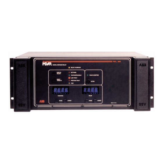
- Page 97 I.L. 40-385.5 I.L. 40-385.5 I.L. 40-385.5 sub 6 9651A07 Figure 3 MDAR (REL-300) Relay Assembly sub 2 2403F38 Figure 4 MDAR (REL-300) Display Panel A-25 A-25 A-25...
- Page 98 3 1502B21 Figure 5 MDAR (REL-300) Relay Assembly...
- Page 99 1 1615C70 Figure 6 MDAR (REL-300) Relay Backplane Board Terminals...
- Page 100 - Ground Backup - Phase Selector Checks and Logic - Non-Pilot Trip Logic - Loss-of-Potential and Loss of Current - Data Communications - Contact Inputs sub 2 9654A12 Figure 7 Overall Flowchart for Microprocessor Software in MDAR (REL-300) Relay A-28 A-28 A-28...
- Page 103 No Load Current sub 3 9655A82 Figure 12 Loss-of-Potential Logic...
- Page 105 Figure 15. MDAR (REL-300) Zone-1 Trip Logic...
- Page 106 1 9659A67 Figure 16. MDAR (REL-300) Zone-2 Trip Logic...
- Page 107 1 1504B04 Figure 17. MDAR (REL-300) Zone-3 Trip Logic...
- Page 108 I.L. 40-385.5 I.L. 40-385.5 I.L. 40-385.5 sub 2 9655A84 Figure 18 MDAR (REL-300) Highset Trip Logic sub 2 9659A68 Figure 19 MDAR (REL-300) Close-into-Fault Trip A-36 A-36 A-36...
- Page 109 I.L. 40-385.5 I.L. 40-385.5 I.L. 40-385.5 sub 1 9658A87 Figure 20 MDAR (REL-300) Unequal-Pole Closing Load Pickup Control sub 1 9655A81 Figure 21 MDAR (REL-300) Inverse Time Overcurrent Ground Backup Logic A-37 A-37 A-37...
- Page 110 I.L. 40-385.5 I.L. 40-385.5 I.L. 40-385.5 sub 1 9654A16 Figure 22 MDAR (REL-300) Zone-1 Extension Scheme sub 2 9656A33 Figure Load-Loss Accelerated Trip Logic A-38 A-38 A-38...
- Page 112 sub 2 1504B29 Figure 25 Load-Loss Accelerated Trip Logic...
- Page 113 I.L. 40-385.5 I.L. 40-385.5 I.L. 40-385.5 sub 1 9659A69 Figure 26 Pilot Trip Relay sub 2 9659A70 Figure 27 POTT/Unblocking, Pilot Trip Logic A-41 A-41 A-41...
- Page 114 * sub 3 1504B30 Figure 28 Carrier Keying/Receiving Logic in POTT/Unblocking Schemes...
- Page 115 I.L. 40-385.5 I.L. 40-385.5 I.L. 40-385.5 sub 1 9659A71 Figure 29 PUTT Scheme sub 1 1504B31 Figure 30 Blocking System Logic A-43 A-43 A-43...
- Page 117 I.L. 40-385.5 I.L. 40-385.5 I.L. 40-385.5 sub 1 9659A72 Figure 33 Weakfeed Application * sub 2 9655A86 Figure 34 FDOG Supplements PLTG for High Rg Faults A-45 A-45 A-45...
- Page 118 I.L. 40-385.5 I.L. 40-385.5 I.L. 40-385.5 sub 1 9654A17 Figure 35 Power Reversal A-46 A-46 A-46...
- Page 119 sub 1 9659A73 Figure 36 Reverse-Block Logic...
- Page 120 sub 1 9654A29 Figure 37 Unequal-Pole Closing on Fault...
- Page 121 * sub 4 1504B32 Figure 38 Simplified MDAR Version 2.60 SPT Logic...
- Page 122 1 1611C12 Figure 39 MDAR Block Diagram...