ABB REF615 Applications Manual
Feeder protection and control
Hide thumbs
Also See for REF615:
- Applications manual (404 pages) ,
- Operation manual (126 pages) ,
- Product manual (57 pages)
Table of Contents
Advertisement
Quick Links
Advertisement
Table of Contents

Related Manuals for ABB REF615


Summary of Contents for ABB REF615
- Page 1 Application Manual Feeder Protection and Control REF615...
- Page 3 Document ID: 1MRS756378 Issued: 04.03.2009 Revision: D Product version: 2.0 © Copyright 2009 ABB. All rights reserved...
- Page 4 Copyright This document and parts thereof must not be reproduced or copied without written permission from ABB, and the contents thereof must not be imparted to a third party, nor used for any unauthorized purpose. The software or hardware described in this document is furnished under a license and may be used, copied, or disclosed only in accordance with the terms of such license.
- Page 5 In case any errors are detected, the reader is kindly requested to notify the manufacturer. Other than under explicit contractual commitments, in no event shall ABB be responsible or liable for any loss or damage resulting from the use of this manual or the application of the equipment.
- Page 6 (Low-voltage directive 2006/95/ EC). This conformity is the result of a test conducted by ABB in accordance with Article 10 of the directive in agreement with the product standards EN 50263 and EN 60255-26 for the EMC directive, and with the product standards EN 60255-6 and EN 60255-27 for the low voltage directive.
-
Page 7: Table Of Contents
Product documentation set............8 Document revision history.............9 Related documentation..............10 Document symbols and conventions..........10 Safety indication symbols............10 Document conventions..............11 Functions, codes and symbols............11 Section 2 REF615 overview............15 Overview...................15 Product version history..............16 PCM600 and IED connectivity package version......16 Operation functionality..............16 Standard configurations...............16 Optional functions................18 Physical hardware................19... - Page 8 Applications.................80 Functions..................80 Default I/O connections............81 Functional diagrams..............82 Functional diagrams for protection.........82 Functional diagram for disturbance recorder and trip circuit supervision..............88 Functional diagrams for control and interlocking....89 Standard configuration F including directional overcurrent protection with voltage protection.............93 REF615 Application Manual...
- Page 9 Three-phase directional overcurrent protection DPHxPDOC................140 Identification.................140 Functionality.................140 Application................140 Three-phase thermal overload protection for overhead lines and cables T1PTTR..............143 Identification.................143 Functionality.................143 Application................144 Earth-fault protection..............145 Non-directional earth-fault protection EFxPTOC.......145 Identification.................145 Functionality.................145 Application................145 Directional earth-fault protection DEFxPDEF......146 Identification.................146 Functionality.................146 Directional earth-fault principles...........146 Application................152 REF615 Application Manual...
- Page 10 Functionality.................168 Application................168 Residual overvoltage protection ROVPTOV......169 Identification.................169 Functionality.................169 Application................169 Negative sequence overvoltage protection NSPTOV....170 Identification.................170 Functionality.................170 Application................170 Positive sequence undervoltage protection PSPTUV....171 Identification.................171 Functionality.................171 Application................171 Section 6 Protection related functions..........181 Three-phase inrush detector INRPHAR.........181 Identification................181 Functionality................181 Application.................181 REF615 Application Manual...
- Page 11 Application.................201 Section 9 Measurement functions..........205 Basic measurements..............205 Three-phase current CMMXU...........205 Identification.................205 Three-phase voltage VMMXU...........205 Identification.................205 Neutral current RESCMMXU.............205 Identification.................205 Residual voltage RESVMMXU..........205 Identification.................205 Sequence current CSMSQI............206 Identification.................206 Phase sequence voltage VSMSQI..........206 Identification.................206 Three-phase power and energy PEMMXU........206 REF615 Application Manual...
- Page 12 Fast trip in Switch on to fault..........223 Section 11 Requirements for measurement transformers....225 Current transformers..............225 Current transformer requirements for non-directional overcurrent protection..............225 Current transformer accuracy class and accuracy limit factor..................225 Non-directional overcurrent protection.........226 Example for non-directional overcurrent protection....227 Section 12 Glossary...............229 REF615 Application Manual...
-
Page 13: Section 1 Introduction
This manual addresses the protection and control engineer responsible for planning, pre-engineering and engineering. The protection and control engineer must be experienced in electrical power engineering and have knowledge of related technology, such as communication and protocols. REF615 Application Manual... -
Page 14: Product Documentation
The manual provides procedures for energizing and checking of external circuitry, setting and configuration as well as verifying settings and performing directional tests. The chapters are organized in chronological order in which the IED should be commissioned. REF615 Application Manual... -
Page 15: Document Revision History
A/20.12.2007 First release B/08.02.2008 Content updated C/02.07.2008 Content updated to correspond to the product version D/04.03.2009 Content updated to correspond to the product version Download the latest revision of the document from the ABB web site http://www.abb.com/substationautomation. REF615 Application Manual... -
Page 16: Related Documentation
The tip icon indicates advice on, for example, how to design your project or how to use a certain function. Although warning hazards are related to personal injury, it should be understood that operation of damaged equipment could, under certain operational conditions, result REF615 Application Manual... -
Page 17: Document Conventions
DPHLPDOC2 3I> → (2) 67-1 (2) Three-phase directional overcurrent, DPHHPDOC1 3I>> → 67-2 high stage Arc protection ARCSARC1 ARC (1) 50L/50NL (1) ARCSARC2 ARC (2) 50L/50NL (2) ARCSARC3 ARC (3) 50L/50NL (3) Table continues on next page REF615 Application Manual... - Page 18 TCS (1) TCM (1) TCSSCBR2 TCS (2) TCM (2) Fuse failure supervision SEQRFUF1 FUSEF Disturbance recorder RDRE1 Circuit breaker condition monitoring SSCBR1 CBCM CBCM Three-phase current measurement CMMXU1 Sequence current measurement CSMSQI1 Table continues on next page REF615 Application Manual...
- Page 19 Section 1 1MRS756378 D Introduction Function IEC 61850 IEC 60617 IEC-ANSI Residual current measurement RESCMMXU1 Residual voltage measurement RESVMMXU1 Three-phase voltage measurement VMMXU1 Sequence voltage measurement VSMSQI1 Three-phase power and energy PEMMXU1 P, E P, E measurement REF615 Application Manual...
-
Page 21: Section 2 Ref615 Overview
Section 2 REF615 overview Overview REF615 is a native IEC 61850 feeder protection IED for selective short-circuit, overcurrent and earth-fault protection. It is applicable to all types of radial isolated neutral networks, resistant earthed networks and compensated networks. REF615 is part of a product family that will cover many protection applications for utility and industry customers. -
Page 22: Product Version History
• Firmware Update Tool • IED Configuration Migration Tool (ICM) • Lifecycle Traceability Tool Download connectivity packages from the ABB web site http:// www.abb.com/substationautomation Operation functionality 2.2.1 Standard configurations The IED is available with six alternative standard configurations. The table indicates the functions supported by the different IED configurations. - Page 23 Section 2 1MRS756378 D REF615 overview Table 2: Standard configurations Description Std. conf. Non-directional overcurrent and directional earth-fault protection A and B Non-directional overcurrent and non-directional earth-fault protection C and D Non-directional overcurrent and directional earth-fault protection with phase-voltage based measurements...
-
Page 24: Optional Functions
Section 2 1MRS756378 D REF615 overview Functionality Three-phase undervoltage, instance 1 ● Three-phase undervoltage, instance 2 ● Three-phase undervoltage, instance 3 ● Three-phase inrush current detection ● ● ● ● ● ● Arc protection with three sensors ○ ○ ○... -
Page 25: Physical Hardware
Section 2 1MRS756378 D REF615 overview • Arc protection • Auto-reclosing • Modbus TCP/IP or RTU/ASCII • IEC 60870-5-103 • DNP 3.0 TCP/IP or serial Physical hardware The IED consists of two main parts: plug-in unit and case. The plug-in unit content depends on the ordered functionality. - Page 26 Section 2 1MRS756378 D REF615 overview The connection diagrams of different hardware modules are presented in this manual. See the Installation Manual for more information about the case and the plug-in unit. Table 5: Number of physical connections in standard configurations...
-
Page 27: Lhmi
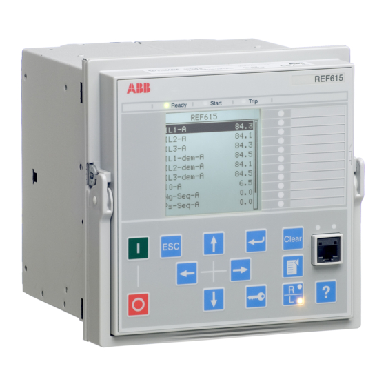
Section 2 1MRS756378 D REF615 overview LHMI A070704 V2 EN Figure 1: LHMI The LHMI of the IED contains the following elements: • Display • Buttons • LED indicators • Communication port The LHMI is used for setting, monitoring and controlling. -
Page 28: Leds
Section 2 1MRS756378 D REF615 overview Character size Rows in view Characters on row Small, mono-spaced (6x12 5 rows pixels) 10 rows with large screen Large, variable width (13x14 4 rows min 8 pixels) 8 rows with large screen The display view is divided into four basic areas:... -
Page 29: Whmi
Section 2 1MRS756378 D REF615 overview A071176 V1 EN Figure 3: LHMI keypad with object control, navigation and command push- buttons and RJ-45 communication port WHMI The WHMI enables the user to access the IED via a web browser. The supported web browser version is Internet Explorer 7.0 or later. -
Page 30: Authorization
Section 2 1MRS756378 D REF615 overview A070754 V3 EN Figure 4: Example view of the WHMI The WHMI can be accessed: • Locally by connecting your laptop to the IED via the front communication port. • Remotely over LAN/WAN. Authorization The user categories have been predefined for the LHMI and the WHMI, each with different rights and default passwords. -
Page 31: Communication
Section 2 1MRS756378 D REF615 overview Table 6: Predefined user categories Username User rights VIEWER Read only access OPERATOR • Selecting remote or local state with (only locally) • Changing setting groups • Controlling • Clearing alarm and indication LEDs and textual indications ENGINEER •... - Page 32 Section 2 1MRS756378 D REF615 overview optic LC connector (100BASE-FX). An optional serial interface is available for RS-232/RS-485 communication. REF615 Application Manual...
-
Page 33: Section 3 Ref615 Variants
REF615 variants REF615 variant list REF615 is intended for protection and control mainly in MV feeder applications. The product has a number of standard configurations covering a wide range of primary circuit configurations in distribution networks based on different system earthing methods. -
Page 34: Standard Configurations
Section 3 1MRS756378 D REF615 variants Signal Matrix Tool With SMT the user can modify the standard configuration according to the actual needs. The IED is delivered from the factory with default connections described in the functional diagrams for BI's, BO's, function to function connections and alarm LEDs. - Page 35 Section 3 1MRS756378 D REF615 variants Functionality Non-directional earth fault, high-set stage ● ● Non-directional earth fault, instantaneous stage ● ● Non-directional sensitive earth fault ● ● Negative-sequence overcurrent, instance 1 ● ● ● ● ● ● Negative-sequence overcurrent, instance 2 ●...
- Page 36 Section 3 1MRS756378 D REF615 variants Functionality Residual voltage ● ● ● ● Power, including power factor ● ● Energy ● ● ● = Included,○ = Optional at the time of the order 1) Basic interlocking functionality: Closing of the circuit breaker can be enabled by a binary input signal. The actual interlocking scheme is implemented outside the IED.
-
Page 37: Connection Diagrams
Section 3 1MRS756378 D REF615 variants 3.2.2 Connection diagrams A071288 V4 EN Figure 5: Connection diagram for configurations A and B (overcurrent and directional earth-fault protection) [1] Additional BIO-module (X110 in the diagram) is included in the IED variant B... - Page 38 Section 3 1MRS756378 D REF615 variants A071290 V3 EN Figure 6: Connection diagram for configurations C and D (overcurrent and non-directional earth-fault protection) [2] Additional BIO-module (X110 in the diagram) is included in the IED variant D REF615 Application Manual...
- Page 39 Section 3 1MRS756378 D REF615 variants GUID-F7601942-ACF2-47E2-8F21-CD9C1D2BC1F0 V2 EN Figure 7: Connection diagram for configurations E and F (directional overcurrent and earth-fault protection with phase-to-phase voltage measurement) REF615 Application Manual...
-
Page 40: Standard Configuration A Including Directional Earth-Fault Protection
Section 3 1MRS756378 D REF615 variants GUID-5D0135B3-3890-497A-8AAA-0362730C8682 V1 EN Figure 8: Connection diagram for configurations E and F (directional overcurrent and earth-fault protection with phase-to-earth voltage measurement) Standard configuration A including directional earth- fault protection 3.3.1 Applications The standard configuration for directional earth-fault protection is mainly intended for cable and overhead line feeder applications in isolated and resonant-earthed distribution networks. -
Page 41: Functions
Section 3 1MRS756378 D REF615 variants 3.3.2 Functions Table 9: Functions included in the REF615 standard configuration with directional earth-fault protection Function IEC 61850 ANSI Three-phase non-directional overcurrent PHLPTOC1 3I> 51P-1 protection, low stage Three-phase non-directional overcurrent PHHPTOC1 3I>> (1) -
Page 42: Default I/O Connections
Section 3 1MRS756378 D REF615 variants 3.3.2.1 Default I/O connections Binary Input Default usage Connector-Pins X120-BI1 Blocking of Overcurrent Instantaneous Stage X120-1,2 X120-BI2 Circuit Breaker Closed position indication X120-3,2 X120-BI3 Circuit Breaker Open position indication X120-4,2 Binary Output Default usage... -
Page 43: Functional Diagrams For Protection
Section 3 1MRS756378 D REF615 variants The analog channels are assigned to different functions as shown in the functional diagrams. The common signal marked with 3I represents the three phase currents. The signal marked with I represents the measured residual current via a core balance CT. - Page 44 Section 3 1MRS756378 D REF615 variants Four overcurrent stages are offered for overcurrent and short-circuit protection. The instantaneous stage (PHIPTOC1) can be blocked by energizing the binary input 1 (X120:1-2). Two negative sequence overcurrent stages (NSPTOC1 and NSPTOC2) are offered for phase unbalance protection. The inrush detection block’s (INRPHAR1) output BLK2H caters the possibility to either block the function or multiply the active settings for any of the shown protection function blocks.
- Page 45 Section 3 1MRS756378 D REF615 variants A071318 V4 EN Figure 10: Directional earth-fault protection Three stages are offered for directional earth-fault protection. In addition, there is a dedicated protection stage (INTRPTEF) either for transient based earth-fault protection or for cable intermittent earth-fault protection in compensated networks.
- Page 46 Section 3 1MRS756378 D REF615 variants A071320 V4 EN Figure 11: Phase discontinuity, thermal overload and circuit breaker failure protection The phase discontinuity protection (PDNPSTOC1) provides protection for interruptions in the normal three-phase load supply, for example, in downed conductor situations. The thermal overload protection (T1PTTR1) provides indication on overload situations.
- Page 47 Section 3 1MRS756378 D REF615 variants A071322 V4 EN Figure 12: Arc protection ARC protection (ARCSARC1-3) and autoreclosing (DARREC1) are included as optional functions. The ARC protection offers individual function blocks for three ARC sensors that can be connected to the IED. Each ARC protection function block has two different operation modes, with or without the phase and residual current check.
-
Page 48: Functional Diagrams For Disturbance Recorder And Trip Circuit Supervision
Section 3 1MRS756378 D REF615 variants command to the circuit breaker, either local or remote, also blocks the autoreclose function via the CBXCBR-selected signal. The circuit breaker availability for the autoreclosure sequence is expressed with the CB_RDY input in DARREC1. In the configuration, this signal is not connected to any of the binary inputs. -
Page 49: Functional Diagrams For Control And Interlocking
Section 3 1MRS756378 D REF615 variants Two separate TCS functions have been included: TCSSCBR1 for PO3 (X100:16-19) and TCSSCBR2 for PO4 (X100:20-23). Both functions are blocked by the Master Trip and the circuit breaker open position signal. The TCS alarm indication is connected to LED 9. - Page 50 Section 3 1MRS756378 D REF615 variants A071328 V3 EN Figure 15: Circuit breaker control The ENA_CLOSE input, that is, enable the closing of the circuit breaker, in the breaker control function block CBXCBR is a combination of the status of the Master Trip.
-
Page 51: Standard Configuration B Including Directional Earth-Fault Protection And Cb Condition Monitoring
PCM600. 3.4.2 Functions Table 11: Functions included in the REF615 standard configuration with directional earth-fault protection Function IEC 61850 ANSI Three-phase non-directional overcurrent PHLPTOC1 3I>... -
Page 52: Default I/O Connections
Section 3 1MRS756378 D REF615 variants Function IEC 61850 ANSI Negative-sequence overcurrent protection, NSPTOC2 > (2) 46 (2) instance 2 Phase discontinuity PDNSPTOC1 > 46PD Three-phase inrush detector INRPHAR1 3I2f> Three-phase thermal protection for feeders, T1PTTR1 3Ith> cables and distribution transformers... -
Page 53: Functional Diagrams
Section 3 1MRS756378 D REF615 variants Binary Output Default usage Connector-Pins X110-SO1 Upstream Overcurrent Blocking X110-14,15,16 X110-SO2 Overcurrent Operate Alarm X110-17,18,19 X110-SO3 Earth fault Operate Alarm X110-20,21,22 Default usage Non-Directional Overcurrent Operate Directional/Intermittent Earth fault Operate Double (Cross country) Earth fault Operate Negative Seq. - Page 54 Section 3 1MRS756378 D REF615 variants A071332 V4 EN Figure 17: Overcurrent protection Four overcurrent stages are offered for overcurrent and short-circuit protection. The instantaneous stage (PHIPTOC1) can be blocked by energizing the binary input 1 (X120:1-2). Two negative sequence overcurrent stages (NPSTOC1 and NPSTOC2) are offered for phase unbalance protection.
- Page 55 Section 3 1MRS756378 D REF615 variants There are four IED variant specific setting groups. Parameters can be set independently for each setting group. The active setting group (1...4) can be changed with a parameter. The change of an active setting group can also be made via a binary input if the binary input is enabled for this.
- Page 56 Section 3 1MRS756378 D REF615 variants Three stages are offered for directional earth-fault protection. In addition, there is a dedicated protection stage (INTRPTEF) either for transient based earth-fault protection or for cable intermittent earth-fault protection in compensated networks. A dedicated non-directional earth-fault protection block (EFHPTOC) is intended for protection against double earth-fault situations in isolated or compensated networks.
- Page 57 Section 3 1MRS756378 D REF615 variants The breaker failure protection (CCBRBRF1) is initiated via the start input by a number of different protection stages in the IED. The breaker failure protection function offers different operating modes associated with the circuit breaker position and the measured phase and residual currents.
- Page 58 Section 3 1MRS756378 D REF615 variants The ARC protection offers individual function blocks for three ARC sensors that can be connected to the IED. Each ARC protection function block has two different operation modes, with or without the phase and residual current check. Operate signals from the ARC protection function blocks are connected to the Master Trip and also to the alarm LED 10 as a common operate indication.
-
Page 59: Functional Diagram For Disturbance Recorder And Trip Circuit Supervision
Section 3 1MRS756378 D REF615 variants 3.4.3.2 Functional diagram for disturbance recorder and trip circuit supervision DISTURBANCE RECORDER RDRE1 PHLPTOC1-start LED7 (DR TRIGGERED) BI#1 TRIGGERED PHHPTOC1-start BI#2 PHHPTOC2-start BI#3 PHIPTOC1-start BI#4 NSPTOC1-start BI#5 NSPTOC2-start BI#6 DEFLPDEF1-start BI#7 DEFLPDEF2-start BI#8 DEFHPDEF1-start... -
Page 60: Functional Diagrams For Control And Interlocking
Section 3 1MRS756378 D REF615 variants 3.4.3.3 Functional diagrams for control and interlocking A071326 V4 EN Figure 22: Master trip The operate signals from the protections described above are connected to the two trip output contacts PO3 (X100:16-19) and PO4 (X100:20-23) via the corresponding Master Trips TRPPTRC1 and TRPPTRC2. - Page 61 Section 3 1MRS756378 D REF615 variants A071344 V4 EN Figure 23: Circuit breaker control There are three disconnector status blocks (DCSXSWI1…3) available in the IED. The remaining two not described in the functional diagram are available in SMT for connection where applicable.
- Page 62 Section 3 1MRS756378 D REF615 variants trip logics and gas pressure alarm and circuit breaker spring charging. The OKPOS output from the DCSXSWI block defines if the disconnector or breaker truck is definitely either open/in test position or close/in service position. This, together with the open earthing switch and non-active trip signals, activates the close-enable signal to the circuit breaker control function block.
- Page 63 Section 3 1MRS756378 D REF615 variants A071346 V4 EN Figure 24: Alarm indication The signal outputs from the IED are connected to give dedicated information on: • start of any protection function SO1 (X100:10-12) • operation (trip) of any protection function SO2 (X100:13-15) •...
-
Page 64: Standard Configuration C Including Non-Directional Earth-Fault
SMT and PST. 3.5.2 Functions Table 13: Functions included in the REF615 standard configuration with non-directional earth- fault protection Function IEC 61850 ANSI... -
Page 65: Default I/O Connections
Section 3 1MRS756378 D REF615 variants Function IEC 61850 ANSI Master Trip TRPPTRC1 Master Trip (1) 94/86 (1) TRPPTRC2 Master Trip (2) 94/86 (2) Trip circuit supervision, instance 1 TCSSCBR1 TCS (1) TCM (1) Trip circuit supervision, instance 2 TCSSCBR2... -
Page 66: Functional Diagrams
Section 3 1MRS756378 D REF615 variants 3.5.3 Functional diagrams The functional diagrams describe the default input, output, alarm LED and function- to-function connections. The default connections can be viewed with SMT and changed according to the application requirements, if necessary. - Page 67 Section 3 1MRS756378 D REF615 variants A071348 V3 EN Figure 25: Overcurrent protection Four overcurrent stages are offered for overcurrent and short-circuit protection. The instantaneous stage (PHIPTOC1) can be blocked by energizing the binary input 1 (X120:1-2). Two negative sequence overcurrent stages (NPSTOC1 and NPSTOC2) are offered for phase unbalance protection.
- Page 68 Section 3 1MRS756378 D REF615 variants for this. To enable the change of an active setting group via a binary input, connect a free binary input with SMT to the ActSG input of the SGCB-block. Table 14: Binary input states and corresponding active setting groups...
- Page 69 Section 3 1MRS756378 D REF615 variants A071352 V4 EN Figure 27: Phase discontinuity, thermal overload and circuit breaker failure protection The phase discontinuity protection (PDNSPTOC1) provides protection for interruptions in the normal three-phase load supply, for example, in downed conductor situations. The thermal overload protection (T1PTTR1) provides indication on overload situations.
- Page 70 Section 3 1MRS756378 D REF615 variants A071354 V4 EN Figure 28: Arc protection ARC protection (ARCSARC1...3) and autoreclosing (DARREC1) are included as optional functions. The ARC protection offers individual function blocks for three ARC sensors that can be connected to the IED. Each ARC protection function block has two different operation modes, with or without the phase and residual current check.
-
Page 71: Functional Diagram For Disturbance Recorder And Trip Circuit Supervision
Section 3 1MRS756378 D REF615 variants input. A control command to the circuit breaker, either local or remote, also blocks the autoreclose function via the CBXCBR-selected signal. The circuit breaker availability for the autoreclosure sequence is expressed with the CB_RDY input in DARREC1. In the configuration, this signal is not connected to any of the binary inputs. -
Page 72: Functional Diagrams For Control And Interlocking
Section 3 1MRS756378 D REF615 variants (TRPPTRC1 and TRPPTRC2) and the circuit breaker open position signal. The TCS alarm indication is connected to LED 9. 3.5.3.3 Functional diagrams for control and interlocking A071358 V4 EN Figure 30: Master trip The operate signals from the protections described above are connected to both of the two trip output contacts PO3 (X100:16-19) and PO4 (X100:20-23) via the corresponding Master Trips TRPPTRC1 and TRPPTRC2. - Page 73 Section 3 1MRS756378 D REF615 variants A071360 V3 EN Figure 31: Circuit breaker control The ENA_CLOSE input, that is, enable the closing of the circuit breaker, in the breaker control function block CBXCBR is a combination of the status of the Master Trip.
-
Page 74: Standard Configuration D Including Non-Directional Earth-Fault Protection And Cb Condition Monitoring
SMT and PST. 3.6.2 Functions Table 15: Functions included in the REF615 standard configuration with non-directional earth- fault protection Function IEC 61850 ANSI... -
Page 75: Default I/O Connections
Section 3 1MRS756378 D REF615 variants Function IEC 61850 ANSI Three-phase inrush detector INRPHAR1 3I2f> Three-phase thermal protection for feeders, T1PTTR1 3Ith> cables and distribution transformers Autoreclosure DARREC1 O → I Circuit breaker failure protection CCBRBRF1 3I>/I >BF 51BF/51NBF Master trip... -
Page 76: Functional Diagrams
Section 3 1MRS756378 D REF615 variants Default usage Non-Directional Overcurrent Operate Non-Directional Earth fault Operate Sensitive Earth fault Operate Negative Seq. Overcurrent/Phase Discontinuity Operate Thermal Overload Alarm Breaker Failure Operate Disturbance Recorder Triggered Circuit Breaker Condition Monitoring Alarm Trip Circuit Supervision Alarm... - Page 77 Section 3 1MRS756378 D REF615 variants A071364 V4 EN Figure 33: Overcurrent protection Four overcurrent stages are offered for overcurrent and short-circuit protection. The instantaneous stage (PHIPTOC1) can be blocked by energizing the binary input 1 (X120:1-2). Two negative sequence overcurrent stages (NPSTOC1 and NPSTOC2) are offered for phase unbalance protection.
- Page 78 Section 3 1MRS756378 D REF615 variants The active setting group (1...4) can be changed with a parameter. The change of an active setting group can also be made via a binary input if the binary input is enabled for this. To enable the change of an active setting group via a binary input, connect a free binary input with SMT to the ActSG input of the SGCB-block.
- Page 79 Section 3 1MRS756378 D REF615 variants A071352 V4 EN Figure 35: Phase discontinuity, thermal overload and circuit breaker failure protection The phase discontinuity protection (PDNSPTOC1) provides protection for interruptions in the normal three-phase load supply, for example, in downed conductor situations. The thermal overload protection (T1PTTR1) provides indication on overload situations.
- Page 80 Section 3 1MRS756378 D REF615 variants A071370 V4 EN Figure 36: Arc protection ARC protection (ARCSARC1-3) and autoreclosing (DARREC1) are included as optional functions. The ARC protection offers individual function blocks for three ARC sensors that can be connected to the IED. Each ARC protection function block has two different operation modes, with or without the phase and residual current check.
-
Page 81: Functional Diagram For Disturbance Recorder And Trip Circuit Supervision
Section 3 1MRS756378 D REF615 variants external start command. It is possible to create individual autoreclose sequences for each input. The autoreclose function can be blocked with the INHIBIT_RECL input. As a default, the operation of some selected protection functions are connected to this input. A control command to the circuit breaker, either local or remote, also blocks the autoreclose function via the CBXCBR-selected signal. -
Page 82: Functional Diagrams For Control And Interlocking
Section 3 1MRS756378 D REF615 variants protection signals and the three binary inputs from X120 are also connected, as well as the autorecloser external start command from the binary input 2 (X110:3-4). Two separate TCS functions are included: TCSSCBR1 for PO3 (X100:16-19) and TCSSCBR2 for PO4 (X100:20-23). - Page 83 Section 3 1MRS756378 D REF615 variants A071376 V4 EN Figure 39: Circuit breaker control There are three disconnector status blocks (DCSXSWI1…3) available in the IED. The remaining two not described in the functional diagram are available in SMT for connection where applicable.
- Page 84 Section 3 1MRS756378 D REF615 variants trip logics and gas pressure alarm and circuit breaker spring charging. The OKPOS output from the DCSXSWI block defines if the disconnector or breaker truck is definitely either open/in test position or close/in service position. This, together with the open earthing switch and non-active trip signals, activates the close-enable signal to the circuit breaker control function block.
- Page 85 Section 3 1MRS756378 D REF615 variants A071378 V4 EN Figure 40: Alarm indication The signal outputs from the IED are connected to give dedicated information on: • start of any protection function SO1 (X100:10-12) • operation (trip) of any protection function SO2 (X100:13-14) •...
-
Page 86: Standard Configuration E Including Directional Earth-Fault Protection With Phase-Voltage Measurement
PCM600. 3.7.2 Functions Table 17: Functions included in the REF615 standard configuration including directional earth- fault protection with phase voltage measurement Function IEC 61850 ANSI... -
Page 87: Default I/O Connections
Section 3 1MRS756378 D REF615 variants Function IEC 61850 ANSI Autoreclosure DARREC1 O → I Circuit breaker failure protection CCBRBRF1 3I>/I >BF 51BF/51NBF Master Trip TRPPTRC1 Master trip (1) 94/86 (1) TRPPTRC2 Master trip (2) 94/86 (2) Trip circuit supervision, instance 1... -
Page 88: Functional Diagrams
Section 3 1MRS756378 D REF615 variants Binary output Default usage Connector pins X100-PO4 Open Circuit Breaker/trip coil 2 X100-20-24 X110-SO1 Upstream Overcurrent Blocking X110-14,15 X110-SO2 Over current operate Alarm X110-17,18 X110-SO3 Earth fault operate Alarm X110-20,21 Default usage Non-directional overcurrent protection operated... - Page 89 Section 3 1MRS756378 D REF615 variants Four overcurrent stages are available for overcurrent and short-circuit protection. The instantaneous stage (PHIPTOC1) can be blocked by energizing the binary input 1 (X120:1-2). Two negative-sequence overcurrent stages (NSPTOC1 and NSPTOC2) are available for phase unbalance protection. The inrush detection block’s (INRPHAR1) output BLK2H enables either blocking the function or multiplying the active settings for any of the shown protection function blocks.
- Page 90 Section 3 1MRS756378 D REF615 variants via a binary input, connect a free binary input with SMT to the ActSG input of the SGCB-block. Table 18: Binary input states and corresponding active setting groups BI state Active setting group The active setting group defined by a parameter is overridden when a binary input is enabled for changing the active setting group.
- Page 91 Section 3 1MRS756378 D REF615 variants GUID-1F3C1F26-6F11-4250-9476-82C47C3AC570 V1 EN Figure 42: Earth-fault protection The phase discontinuity protection (PDNSPTOC1) provides protection for interruptions in the normal three-phase load supply, for example, in downed conductor situations. The thermal overload protection (T1PTTR1) provides indication on overload situations.
- Page 92 Section 3 1MRS756378 D REF615 variants GUID-8BD4614B-2C4D-475E-ADC3-A376E213BF3C V1 EN Figure 43: Phase discontinuity, thermal overload and circuit breaker failure protection ARC protection (ARCSARC1...3) and autoreclosing (DARREC1) are included as optional functions. The ARC protection offers individual function blocks for three ARC sensors that can be connected to the IED.
- Page 93 Section 3 1MRS756378 D REF615 variants GUID-86A27183-AE21-4420-AA8D-B53A43C77BBE V1 EN Figure 44: Arc protection The autorecloser is configured to be initiated by operate signals from a number of protection stages through the INIT1-5 inputs. It is possible to create individual autoreclose sequences for each input.
-
Page 94: Functional Diagram For Disturbance Recorder And Trip Circuit Supervision
Section 3 1MRS756378 D REF615 variants The autoreclose sequence in progress indication is connected to the alarm LED 11. 3.7.3.2 Functional diagram for disturbance recorder and trip circuit supervision GUID-4BE45287-D708-41F3-851A-084A9AC3265E V1 EN Figure 45: Disturbance recorder The disturbance recorder has 64 digital inputs, of which 35 are connected as default. -
Page 95: Functional Diagrams For Control And Interlocking
Section 3 1MRS756378 D REF615 variants The fuse failure supervision provides functionality for detecting failures in voltage measurement circuits. Failures, such as open miniature circuit breaker, are detected and the alarm is connected to the supervision alarm LED 9. Failures in current measuring circuits are detected by the current measuring circuit supervision function CCRDIF. - Page 96 Section 3 1MRS756378 D REF615 variants GUID-4963C315-60C2-4C60-BE7F-B18D87A8D35E V1 EN Figure 47: Master trip The TRPPTRC1 and 2 blocks provide the lockout/latching function, event generation and the trip signal duration setting. If the lockout operation mode is selected, one binary input can be re-assigned to the RST_LKOUT input of the Master Trip to enable external reset with a push button.
- Page 97 Section 3 1MRS756378 D REF615 variants GUID-4DED2926-A92A-4F6A-BCAA-7D9CD24ACFC8 V1 EN Figure 48: Circuit breaker control The binary inputs 5 and 6 of the additional card X110 are used for busbar disconnector (DCSXSWI1) or circuit breaker truck position indication. Table 19: Device positions indicated by binary inputs 5 and 6...
- Page 98 Section 3 1MRS756378 D REF615 variants together with the open earthing switch and non-active trip signals, activates the close- enable signal to the circuit breaker control function block. The open operation is always enabled. The autorecloser close command signals are directly connected to the output contact PO1 (X100:6-7).
-
Page 99: Standard Configuration F Including Directional Overcurrent Protection With Voltage Protection
SMT and PST. 3.8.2 Functions Table 20: Functions included in the REF615 standard configuration including directional overcurrent protection with voltage protection Function IEC 61850 ANSI... - Page 100 Section 3 1MRS756378 D REF615 variants Function IEC 61850 ANSI Directional earth-fault protection, low stage, DEFLPDEF1 > → (1) 67N-1 (1) instance 1 Directional earth-fault protection, low stage, DEFLPDEF2 > → (2) 67N-1 (2) instance 2 Directional earth-fault protection, high stage DEFHPDEF1 >>...
-
Page 101: Default I/O Connections
Section 3 1MRS756378 D REF615 variants 3.8.2.1 Default I/O connections Binary input Default usage Connector pins X110-BI1 MCB open X110-1,2 Directional Earth Fault Protection's Basic Angle X110-BI2 Control X110-3,4 X110-BI3 Circuit breaker low gas pressure indication X110-5,6 X110-BI4 CB spring charged indication... -
Page 102: Functional Diagrams
Section 3 1MRS756378 D REF615 variants 3.8.3 Functional diagrams The functional diagrams describe the default input, output, alarm LED and function- to-function connections. The default connections can be viewed with SMT and changed according to the application requirements. The analog channels, measurements from CTs and VTs, have fixed connections towards the different function blocks inside the IED’s standard configuration. - Page 103 Section 3 1MRS756378 D REF615 variants GUID-F0BE506C-0A96-4AA2-AC55-FFD9BCD23951 V1 EN Figure 50: Directional overcurrent protection and inrush indication All operate signals are connected to the Master Trip and to the alarm LEDs. LED 1 is used for overcurrent and LED 4 for negative-sequence overcurrent protection operate indication.
- Page 104 Section 3 1MRS756378 D REF615 variants The active setting group defined by a parameter is overridden when a binary input is enabled for changing the active setting group. Three stages are offered for directional earth-fault protection. In addition, there is a dedicated protection stage (INTRPTEF) either for transient-based earth-fault protection or for cable intermittent earth-fault protection in compensated networks.
- Page 105 Section 3 1MRS756378 D REF615 variants The phase discontinuity protection (PDNSPTOC1) provides protection for interruptions in the normal three-phase load supply, for example, in downed conductor situations. The thermal overload protection (T1PTTR1) provides indication on overload situations. The operate signal of the phase discontinuity protection is connected to the Master Trip and also to an alarm LED.
- Page 106 Section 3 1MRS756378 D REF615 variants GUID-EC907A8E-9CF0-4150-A394-FFBAF30A8725 V1 EN Figure 53: Arc protection The ARC protection offers individual function blocks for three ARC sensors that can be connected to the IED. Each ARC protection function block has two different operation modes, with or without the phase and residual current check. Operate signals from the ARC protection function blocks are connected to the Master Trip and also to the alarm LED 10 as a common operate indication.
- Page 107 Section 3 1MRS756378 D REF615 variants input. A control command to the circuit breaker, either local or remote, also blocks the autorreclose function via the CBXCBR-selected signal. The circuit breaker availability for the autorreclosure sequence is expressed with the binary input 4 (X110:6-7) by connecting the input signal to the CB_RDY input. In case this signal is completely removed from the autorreclose function block with SMT, the function assumes that the breaker is available all the time.
-
Page 108: Functional Diagram For Disturbance Recorder And Trip Circuit Supervision
Section 3 1MRS756378 D REF615 variants GUID-A77D0608-E3F2-4D3D-8907-15034FC42D51 V1 EN Figure 55: Positive-sequence undervoltage and negative-sequence overvoltage protection The residual overvoltage protection (ROVPTOV) provides earth fault protection by detecting abnormal level of residual voltage. It can be used, for example, as a non- selective backup protection for the selective directional earth-fault functionality. - Page 109 Section 3 1MRS756378 D REF615 variants GUID-A2EBA677-AEF4-451B-807B-20F50D5894C7 V1 EN Figure 57: Disturbance recorder Two separate TCS functions are included: TCSSCBR1 for PO3 (X100:16-19) and TCSSCBR2 for PO4 (X100:20-23). Both functions are blocked by the Master Trip (TRPPTRC1 and TRPPTRC2) and the circuit breaker open position signal. The TCS alarm indication is connected to LED 9.
-
Page 110: Functional Diagrams For Control And Interlocking
Section 3 1MRS756378 D REF615 variants GUID-F06A3FEF-2C72-49A4-928F-D301335EC2C6 V1 EN Figure 58: Trip circuit supervision 3.8.3.3 Functional diagrams for control and interlocking The operate signals from the protections are connected to the two trip output contacts PO3 (X100:16-19) and PO4 (X100:20-23) via the corresponding Master Trips TRPPTRC1 and TRPPTRC2. - Page 111 Section 3 1MRS756378 D REF615 variants GUID-300441A3-AE3C-4BBF-8C5A-B5CA8BA4EF53 V1 EN Figure 59: Master trip Three disconnector status blocks (DCSXSWI1…3) are available in the IED. The remaining two not described in the functional diagram are available in SMT for connection where applicable.
- Page 112 Section 3 1MRS756378 D REF615 variants GUID-DE498CFB-A256-4275-9A1F-5EF3B09046F4 V1 EN Figure 60: Circuit breaker control The binary inputs 5 and 6 of the additional card X110 are used for busbar disconnector (DCSXSWI1) or circuit-breaker truck position indication. Table 22: Device positions indicated by binary inputs 5 and 6...
- Page 113 Section 3 1MRS756378 D REF615 variants together with the open earthing switch and non-active trip signals, activates the close- enable signal to the circuit breaker control function block. The open operation is always enabled. The auto-recloser close command signals are directly connected to the output contact PO1 (X100:6-7).
- Page 114 Section 3 1MRS756378 D REF615 variants GUID-79EB68EE-F160-402E-A841-BC6D074E7294 V1 EN Figure 61: Alarm indication The signal outputs from the IED are connected to give dedicated information on: REF615 Application Manual...
- Page 115 Section 3 1MRS756378 D REF615 variants • Start of any protection function SO1 (X100:10-12) • Operation (trip) of any protection function SO2 (X100:13-14) • Operation (trip) of any stage of the overcurrent protection function SO2 (X110:17-19) • Operation (trip) of any stage of the earth-fault protection function SO3 (X110:20-22) •...
-
Page 117: General Parameters
Unit Step Default Description Primary voltage 0.001...440.000 0.001 20.000 Primary rated voltage Secondary voltage 1=100V 1=100V Secondary rated 2=110V voltage 3=115V 4=120V VT connection 1=Wye 2=Delta Wye or delta VT 2=Delta connection Table continues on next page REF615 Application Manual... - Page 118 BOOLEAN 0=False Status of Alarm LED 8 Alarm LED 9 BOOLEAN 0=False Status of Alarm LED 9 Alarm LED 10 BOOLEAN 0=False Status of Alarm LED 10 Alarm LED 11 BOOLEAN 0=False Status of Alarm LED 11 REF615 Application Manual...
- Page 119 Alarm LED mode 0=Follow-S 0=Follow-S Alarm mode for LED 9 1=Follow-F 2=Latched-S 3=LatchedAck-F-S Description Alarm LEDs LED 9 Description of alarm Alarm LED mode 0=Follow-S 0=Follow-S Alarm mode for LED 10 1=Follow-F 2=Latched-S 3=LatchedAck-F-S Table continues on next page REF615 Application Manual...
- Page 120 Binary input settings Parameter Values (Range) Unit Step Default Description Threshold voltage 18...176 Binary input threshold voltage Input osc. level 2...50 events/s Binary input oscillation suppression threshold Input osc. hyst 2...50 events/s Binary input oscillation suppression hysteresis REF615 Application Manual...
- Page 121 Blocking mode 1=Freeze timer 1=Freeze timer Behaviour for function BLOCK inputs 2=Block all 3=Block OPERATE output Bay name REF615 Bay name in system SG follow input 0=False 0=False Enable setting group change to follow the input 1=True state Table 34:...
- Page 122 -1=Not in use Active Class2 Frame 4 for instance 0=User frame 1=Standard frame 1 2=Standard frame 2 3=Standard frame 3 4=Standard frame 4 5=Standard frame 5 6=Private frame 6 7=Private frame 7 Table continues on next page REF615 Application Manual...
- Page 123 -1=Not in use Active Class2 Frame 2 for instance 0=User frame 1=Standard frame 1 2=Standard frame 2 3=Standard frame 3 4=Standard frame 4 5=Standard frame 5 6=Private frame 6 7=Private frame 7 Table continues on next page REF615 Application Manual...
- Page 124 Internal Overflow 0=False 0=False Internal Overflow: TRUE-System 1=True level overflow occured (indication only) Table 36: IEC 61850-8-1MMS settings Parameter Values (Range) Unit Step Default Description Unit mode 1=Primary 0=Nominal IEC 61850-8-1 unit mode 0=Nominal 2=Primary-Nominal REF615 Application Manual...
- Page 125 CtlStructPWd3 **** Password for Modbus control struct 3 CtlStructPWd4 **** Password for Modbus control struct 4 CtlStructPWd5 **** Password for Modbus control struct 5 CtlStructPWd6 **** Password for Modbus control struct 6 Table continues on next page REF615 Application Manual...
- Page 126 1=32 bit AI; 2=16 bit AI; 3=32 bit AI without flag; 4=16 bit AI without flag. Default Var Obj 32 1...4 1=32 bit AI event; 2=16 bit AI event; 3=32 bit AI event with time; 4=16 bit AI event with time. REF615 Application Manual...
- Page 127 2=RS485 4Wire COM2 3=RS232 no handshake 4=RS232 with handshake CTS delay 0...60000 CTS delay for COM2 RTS delay 0...60000 RTS delay for COM2 Baudrate 1=300 6=9600 Baudrate for COM2 2=600 3=1200 4=2400 5=4800 6=9600 7=19200 8=38400 9=57600 10=115200 REF615 Application Manual...
- Page 128 Daylight savings time off, time (hh:mm) DST off date 25.09. Daylight savings time off, date (dd:mm) DST off day 0=Not in use 0=Not in use Daylight savings time off, 1=Mon day of week 2=Tue 3=Wed 4=Thu 5=Fri 6=Sat 7=Sun REF615 Application Manual...
- Page 129 Connectors 1-2 X110-Input 2 BOOLEAN Connectors 3-4 X110-Input 3 BOOLEAN Connectors 5-6c X110-Input 4 BOOLEAN Connectors 7-6c X110-Input 5 BOOLEAN Connectors 8-9c X110-Input 6 BOOLEAN Connectors 10-9c X110-Input 7 BOOLEAN Connectors 11-12c X110-Input 8 BOOLEAN Connectors 13-12c REF615 Application Manual...
- Page 130 5...1000 Connectors 1-2c Input 2 filter time 5...1000 Connectors 3-2c Input 3 filter time 5...1000 Connectors 4-2c Input 4 filter time 5...1000 Connectors 5-6 Input 1 inversion 0=False 0=False Connectors 1-2c 1=True Table continues on next page REF615 Application Manual...
- Page 131 Connectors 7-8c Input 6 filter time 5...1000 Connectors 9-8c Input 1 inversion 0=False 0=False Connectors 1-2c 1=True Input 2 inversion 0=False 0=False Connectors 3-2c 1=True Input 3 inversion 0=False 0=False Connectors 4-5c 1=True Table continues on next page REF615 Application Manual...
-
Page 132: Self-Supervision
The IED's extensive self-supervision system continuously supervises the software and the electronics. It handles run-time fault situations and informs the user about the existing faults via the LHMI and the communication. There are two types of fault indications. • Internal faults • Warnings REF615 Application Manual... -
Page 133: Internal Faults
Card in slot X100 is wrong type or does not Conf. error,X100 belong to the original composition. Internal Fault Card in slot X110 is wrong type, is missing Conf. error,X110 or does not belong to the original composition. Table continues on next page REF615 Application Manual... -
Page 134: Warnings
Additional information Warning A watchdog reset has occurred. Watchdog reset Warning The auxiliary supply voltage has dropped Power down det. too low. Warning Error when building the IEC 61850 data IEC61850 error model. Table continues on next page REF615 Application Manual... -
Page 135: Time Synchronization
If set to “None”, the clock is free-running and the settings Date and Time can be used to set the time manually. Other setting values activate a communication protocol that provides the time synchronization. Only one synchronization method can be active at a time but SNTP provides time master redundancy. REF615 Application Manual... -
Page 136: Parameter Setting Groups
As no reboot is necessary, the time synchronization starts immediately after the IRIG-B sync source is selected and the IRIG-B signal source is connected. ABB has tested the IRIG-B with the following clock masters: • Tekron TTM01 GPS clock with IRIG-B output •... - Page 137 Setting Value Default Description Access rights Setting group Active group 1...4 Selected RWRW active group Not all parameters belong to a setting group. For example protection function enable/ disable settings are not part of a setting group. REF615 Application Manual...
-
Page 139: Three-Phase Current Protection
The function contains a blocking functionality. It is possible to block function outputs, timers or the function itself, if desired. 5.1.1.3 Application PHxPTOC is used in several applications in the power system. The applications include but are not limited to: REF615 Application Manual... - Page 140 LV-side busbars. In this case the magnitude of the fault current is typically lower than 12xI depending on the fault location and transformer impedance. Consequently, the protection must operate as fast as possible taking into REF615 Application Manual...
- Page 141 LV-side faults without impairing the selectivity. Also, the security degree REF615 Application Manual...
- Page 142 100 ms, which reduces the fault current in to a half. After this the incoming feeder relay unit of the faulted bus section trips the breaker in approximately 250 ms (relaying time), which becomes the total fault clearing time in this case. REF615 Application Manual...
- Page 143 This is important in order to maintain selectivity and also for the protection to operate without additional time delays. For additional information about available measuring modes and current transformer requirements, refer to section where general function block features are described in the IED technical manual. REF615 Application Manual...
- Page 144 By this way the start value is multiplied with a predefined setting during the inrush situation and nuisance tripping can be avoided. REF615 Application Manual...
- Page 145 All the points mentioned earlier, required to define the overcurrent protection parameters, can be expressed simultaneusly in a coordination plan. In Figure 65 the coordination plan shows an example of operation characteristics in the LV-side incoming feeder and radial outgoing feeder. REF615 Application Manual...
-
Page 146: Three-Phase Directional Overcurrent Protection Dphxpdoc
The function contains a blocking functionality. It is possible to block function outputs, timers or the function itself, if desired. 5.1.2.3 Application DPHxPDOC is used as short-circuit protection in three-phase distribution or sub transmission networks operating at 50 or 60 Hz. REF615 Application Manual... - Page 147 DPHxPDOC can be used for parallel operating transformer applications. In these applications, there is a possibility that the fault current can also be fed from the LV- side up to the HV-side. Therefore, the transformer is also equipped with directional overcurrent protection. REF615 Application Manual...
- Page 148 The way directional overcurrent functions are used in closed ring applications can be illustrated. The arrows define the operating direction of the directional functionality. The double arrows define the non- directional functionality where faults can be detected in both directions. REF615 Application Manual...
-
Page 149: Three-Phase Thermal Overload Protection For Overhead Lines And Cables T1Pttr
A thermal overload is in some cases not detected by other protection functions, and the introduction of the thermal overload function T1PTTR allows the protected circuit to operate closer to the thermal limits. REF615 Application Manual... -
Page 150: Application
This enables actions in the power system to be done before dangerous temperatures are reached. If the temperature continues to increase to the maximum allowed temperature value, the protection initiates a trip of the protected line. REF615 Application Manual... -
Page 151: Earth-Fault Protection
Many applications require several steps using different current start levels and time delays. EFxPTOC consists of three different protection stages: REF615 Application Manual... -
Page 152: Directional Earth-Fault Protection Defxpdef
I to that of the residual voltage (-U Relay characteristic angle The Characteristic angle, also known as Relay Characteristic Angle (RCA), Relay Base Angle or Maximum Torque Angle (MTA), is used in the "Phase angle" mode REF615 Application Manual... - Page 153 GUID-57B7D22F-221A-480D-9145-614002A423A2 V1 EN Figure 69: Definition of the relay characteristic angle, RCA=0 degrees in a compensated network Example 2. The "Phase angle" mode is selected, solidly earthed network (φRCA = +60 deg) => Characteristic angle = +60 deg REF615 Application Manual...
- Page 154 GUID-F3A658D8-B667-4E85-9528-E1D024954B32 V1 EN Figure 70: Definition of the relay characteristic angle, RCA=+60 degrees in a solidly earthed network Example 3. The "Phase angle" mode is selected, isolated network (φRCA = -90 deg) => Characteristic angle = -90 deg REF615 Application Manual...
- Page 155 Min forward angle, Max forward angle, Min reverse angle or Max reverse angle. The figure below describes how earth fault current is defined in isolated neutral networks. For definitions of different directional earth-fault characteristics, refer to the Technical manual. REF615 Application Manual...
- Page 156 This is done with an auxiliary input in the relay which receives a signal from an auxiliary switch of the disconnector of the Petersen coil in REF615 Application Manual...
- Page 157 There is no need to change any settings when a Petersen coil or an earthing resistor is switched on or off. Auxiliary switches and other pieces of extra hardware are no longer required for ensuring the selectivity of the directional earth- fault protection. REF615 Application Manual...
-
Page 158: Application
In addition, the magnitude of the fault current is almost independent of the fault location in the network. The function uses the residual current components I cos(φ) or I sin(φ) according to the earthing method, where φ is the angle between the residual current and the REF615 Application Manual... - Page 159 If the neutral of the network is either isolated or earthed with high impedance, a core balance current transformer is recommended to be used in earth-fault protection. To ensure sufficient accuracy of residual current measurements and consequently the selectivity of the scheme, the REF615 Application Manual...
-
Page 160: Transient/Intermittent Earth-Fault Protection Intrptef
IED. A070697 V2 EN Figure 75: Connection of measuring transformers 5.2.3 Transient/intermittent earth-fault protection INTRPTEF 5.2.3.1 Identification Table 65: Function identification IEC 61850 identification: INTRPTEF IEC 60617 identification: I0> ->IEF ANSI/IEEE C37.2 device number: 67NIEF REF615 Application Manual... -
Page 161: Functionality
Intermittent earth-fault transients cause damping sinusoidal residual voltage. In case of successive intermittent transients, the residual voltage level may continuously stay high. The substation residual voltage has usually been used in the substation back-up REF615 Application Manual... - Page 162 The requirement that one additional transient is needed after the operate delay time is exceeded can cause additional operate time delays. However, this functionality is implemented to prevent unwanted trips. REF615 Application Manual...
- Page 163 INTRPTEF has started and the operate delay time has elapsed, the function operates and sends a trip command to the circuit breaker. The following figure shows the transient earth fault detection and operation of the INTRPTEF function. REF615 Application Manual...
-
Page 164: Unbalance Protection
Figure 78: Transient earth-fault situation and operation of INTRPTEF during a fault Unbalance protection 5.3.1 Negative phase-sequence current protection NSPTOC 5.3.1.1 Identification Table 66: Function identification IEC 61850 identification: NSPTOC IEC 60617 identification: I2> ANSI/IEEE C37.2 device number: REF615 Application Manual... -
Page 165: Functionality
Multiple time curves and time multiplier settings are also available for coordinating with other devices in the system. 5.3.2 Phase discontinuity PDNSPTOC 5.3.2.1 Identification Table 67: Function identification IEC 61850 identification: PDNSPTOC IEC 60617 identification: I2/I1> ANSI/IEEE C37.2 device number: 46PD REF615 Application Manual... -
Page 166: Functionality
The unbalance of the network is detected by monitoring the negative and positive sequence current ratio, where the negative-phase sequence current value is I and I is the positive-phase sequence current value. The unbalance is calculated using Equation 3 REF615 Application Manual... - Page 167 Current quantities during the broken fault in phase A, together with the ratio of negative and positive sequence currents, are presented in Figure 80 IECA070698 V1 EN Figure 80: Three-phase currents, positive and negative sequence currents and the ratio of sequence currents during broken conductor fault in phase REF615 Application Manual...
-
Page 168: Arc Protection Arcsarc
The function detects light from an arc either locally or via a remote light signal. Locally, the light is detected by lens sensors connected to the inputs Light sensor 1, Light sensor 2, or Light sensor 3 on the serial communication module of the relay. REF615 Application Manual... - Page 169 The maximum recommended installation distance between the two lens sensors in the busbar area is six meters and the maximum distance from a lens sensor to the end of the busbar is three meters. REF615 Application Manual...
- Page 170 IEDs protecting the outgoing feeders, which in turn results in tripping of all circuit breakers of the outgoing feeders. For maximum safety, the IEDs can be configured to trip all the circuit breakers regardless of where the arc is detected. REF615 Application Manual...
- Page 171 IEDs protecting the outgoing feeders, which in turn results in tripping of all circuit breakers of the outgoing feeders. REF615 Application Manual...
-
Page 172: Voltage Protection
Figure 83: Arc protection with several IEDs and a separate arc protection system Voltage protection 5.5.1 Overvoltage protection PHPTOV 5.5.1.1 Identification Table 69: Function identification IEC 61850 identification PHPTOV IEC 60617 identification 3U> ANSI/IEEE C37.2 device number REF615 Application Manual... -
Page 173: Functionality
It is essential to provide power frequency overvoltage protection, in the form of time delayed element, either IDMT or DT to prevent equipment damage. 5.5.2 Undervoltage protection PHPTUV 5.5.2.1 Identification Table 70: Function identification IEC 61850 identification PHPTUV IEC 60617 identification 3U< ANSI/IEEE C37.2 device number REF615 Application Manual... -
Page 174: Functionality
PHPTOV prevents sensitive equipment from running under conditions that could cause overheating and thus shorten their life time expectancy. In many cases, PHPTOV is a useful function in circuits for local or remote automation processes in the power system. REF615 Application Manual... -
Page 175: Residual Overvoltage Protection Rovptov
The residual voltage can be calculated internally based on the measurement of the three-phase voltage. This voltage can also be measured by a single-phase voltage transformer, located between a transformer star point and earth, or by using an open- delta connection of three single-phase voltage transformers. REF615 Application Manual... -
Page 176: Negative Sequence Overvoltage Protection Nsptov
If there is a considerable degree of voltage unbalance in the network, the rotating machines should not be connected to the network at all. This logic can be implemented by inhibiting the closure of the circuit breaker if the NSPTOV operation has started. REF615 Application Manual... -
Page 177: Positive Sequence Undervoltage Protection Psptuv
There is then a risk of an autoreclosure taking place when the voltages of different parts of the network do not synchronize, which is a straining incident for the power station. Another risk is that the generator REF615 Application Manual... - Page 178 ≈ (Equation 4) GUID-27F4A2D7-C8B7-4A9D-A915-D59D4B92CB6E V1 EN two-phase short circuit ≈ (Equation 5) GUID-C2E64AF0-0776-42A9-8BF7-5EE12C5A113E V1 EN two-phase earth fault 0 33 ≈ (Equation 6) GUID-6CE59803-DC3E-4B32-A4D4-71F00C5F2B21 V1 EN REF615 Application Manual...
- Page 179 PSPTUV operation de-energizes the faulty line even if the fault current fed by the power station is too low to start the overcurrent protection between the power station and the fault, but high enough to maintain the arc. REF615 Application Manual...
- Page 180 1 1 0 5 − − ’ ’ (Equation 8) GUID-0833A49D-71B3-40DC-B920-5B88882C3A03 V1 EN short circuit reactance between the power station and the fault reduced to the voltage level of the power station REF615 Application Manual...
- Page 181 The actual setting should be slightly, for example, 10 percent higher than the value calculated to allow some marginal for the fault resistance and other factors that may make the U value higher: Voltage start value 1.1 × 0.74 = 0.81 REF615 Application Manual...
- Page 182 Section 5 1MRS756378 D Protection functions GUID-DD28B178-6102-4CEF-BF81-93A3CFE8D55E V1 EN Figure 84: A fault on a radial line resulting in a loss-of-grid condition REF615 Application Manual...
- Page 183 If all circuit breaker operations are three-phase ones for all faults, also a single phase- to-earth fault results in an islanding condition and the setting has to be calculated according to a single-phase fault. REF615 Application Manual...
- Page 184 Section 5 1MRS756378 D Protection functions GUID-A6D0D737-9E83-47B4-A8E6-1543D03F45E9 V1 EN Figure 86: Overreaching distance relays give rise to a loss-of-grid situation at a line fault GUID-7D702BF5-3937-4273-8964-EE8995601B3C V1 EN Figure 87: Equivalent circuit used in the calculation REF615 Application Manual...
- Page 185 The overreaching first zone of the distance relay of the substation A covers a length of 0.3 Ω of the line BC. The overreaching first zone of the distance relay of the substation C covers a length of 0.25 Ω of the line BA => X = 0.3 Ω. REF615 Application Manual...
- Page 186 Also, the short circuit reactance of the transformer has to be added to the network short circuit reactance if the voltage is measured at the generator side of the transformer. REF615 Application Manual...
-
Page 187: Three-Phase Inrush Detector Inrphar
The inrush detection function can be used to selectively block overcurrent and earth- fault function stages when the ratio of second harmonic component over the fundamental component exceeds the set value. Other applications of this function include the detection of inrush in lines connected to a transformer. REF615 Application Manual... -
Page 188: Circuit Breaker Failure Protection Ccbrbrf
CCBRBRF IEC 60617 identification: 3I>I >BF ANSI/IEEE C37.2 device number: 51BF/51NBF 6.2.2 Functionality The breaker failure function CCBRBRF is activated by trip commands from the protection functions. The commands are either internal commands to the terminal or REF615 Application Manual... -
Page 189: Application
The back-up trip timer is also initiated at the same time as the retrip timer. If CCBRBRF detects a failure in tripping the fault within the set back-up delay time, which is longer than the retrip time, it sends a back-up trip signal to the chosen back- REF615 Application Manual... -
Page 190: Protection Trip Conditioning Trpptrc
The user can set the minimum trip pulse length when the non-latched mode is selected. It is also possible to select the latched or lockout mode for the trip signal. REF615 Application Manual... -
Page 191: Application
The TRIP output is connected to the binary outputs on the IO board. This signal can also be used for other purposes within the IED, for example when starting the breaker failure protection. TRPPTRC is used for simple three-phase tripping applications. A070881 V1 EN Figure 90: Typical TRPPTRC connection REF615 Application Manual... - Page 192 “Lockout” mode. It is also possible to reset the “Latched” mode remotely through a separate communication parameter. The minimum pulse trip pulse function is not active when using the “Lockout” or “Latched” modes but only when the “Non-latched” mode is selected. REF615 Application Manual...
-
Page 193: Trip Circuit Supervision Tcsscbr
TCS can see the trip circuit through R . The R resistor should have such a resistance that the current through the resistance remains small, that is, it does not harm or overload the circuit breaker's trip coil. REF615 Application Manual... - Page 194 A051906 V2 EN Figure 92: Operating principle of the trip-circuit supervision without an external resistor. The circuit breaker open indication is set to block TCSSCBR when the circuit breaker is open. REF615 Application Manual...
- Page 195 Current flow in parallel trip contacts and trip-circuit supervision In case of parallel trip contacts, the recommended way to do the wiring is that the TCS test current flows through all wires and joints as shown in the following figure. REF615 Application Manual...
- Page 196 An auxiliary relay can be used between the protection IED trip contact and the circuit breaker coil. This way the breaking capacity question is solved, but the TCS circuit REF615 Application Manual...
- Page 197 TCS contact. In this case, erroneous alarming can occur. At lower (<48V DC) auxiliary circuit operating voltages, it is recommended to use the circuit breaker position to block unintentional operation of TCS. The usage of the position indication is described earlier in this chapter REF615 Application Manual...
- Page 198 The following picture shows incorrect usage of a TCS circuit when only one of the contacts is used. REF615 Application Manual...
- Page 199 IED R3 and the resistor burns immediately. As proven with the previous examples, both trip contacts must operate together. Attention should also be paid for correct usage of the trip-circuit supervision while, for example, testing the IED. REF615 Application Manual...
-
Page 200: Current Circuit Supervision Ccrdif
CCRDIF calculates internally the sum of phase currents (I_A, I_B and I_C) and compares the sum against the measured single reference current (I_REF). The reference current must originate from other three phase CT cores than the phase REF615 Application Manual... -
Page 201: Application
Reference current measured with core balanced current transformer The function compares the sum of phase currents with the current measured with the core balanced CT. REF615 Application Manual... - Page 202 Connection diagram for reference current measurement with core balanced current transformer Current measurement with two independent three-phase sets of CT cores The figures show diagrams of connections where the reference current is measured with two independent three-phase sets of CT cores REF615 Application Manual...
- Page 203 When using the measurement core for reference current measurement, it should be noted that the saturation level of the measurement core is much lower than with the protection core. This should be taken into account when setting the current circuit supervision function. REF615 Application Manual...
- Page 204 The currents must be measured with two independent cores, that is, the phase currents must be measured with a different core than the reference current. A connection diagram shows an example of a case where the phase currents and the reference currents are measured from the same core. REF615 Application Manual...
-
Page 205: Fuse Failure Supervision Seqrfuf
IED to avoid unwanted operations that might occur otherwise. SEQRFUF basically has two different algorithms, a negative sequence based algorithm and delta voltage and delta current algorithm. REF615 Application Manual... -
Page 206: Application
Since the voltage dependence differs between these functions, SEQRFUF has two outputs for this purpose. Some voltage-dependent functions should be blocked whenever a fuse failure occurs. The FUSEF_U output is intended to block these functions REF615 Application Manual... -
Page 207: Circuit Breaker Condition Monitoring Sscbr
The function calculates the number of days the circuit breaker has remained inactive, that is, has stayed in the same open or closed state. There is also the possibility to set an initial inactive day. REF615 Application Manual... - Page 208 The wearing in the breaker depends on the tripping current, and the remaining life of the breaker is estimated from the circuit breaker trip curve provided by the manufacturer. Example for estimating the remaining life of a circuit breaker REF615 Application Manual...
- Page 209 (Equation 12) A070794 V1 EN Rated operating current = 630 A Rated fault current = 16 kA Op number rated = 30000 Op number fault = 20 Calculation for estimating the remaining life REF615 Application Manual...
- Page 210 A binary input is available based on the pressure levels in the function, and alarms are generated based on these inputs. REF615 Application Manual...
-
Page 211: Basic Measurements
IEC 61850 identification: VMMXU IEC 60617 identification: ANSI/IEEE C37.2 device number: 9.1.3 Neutral current RESCMMXU 9.1.3.1 Identification Table 84: Function identification IEC 61850 identification: RESCMMXU IEC 60617 identification: ANSI/IEEE C37.2 device number: 9.1.4 Residual voltage RESVMMXU 9.1.4.1 Identification REF615 Application Manual... -
Page 212: Sequence Current Csmsqi
Function identification IEC 61850 identification: PEMMXU IEC 60617 identification: P, E ANSI/IEEE C37.2 device number: P, E 9.1.8 Functions The three-phase current measurement function, CMMXU, is used for monitoring and metering the phase currents of the power system. REF615 Application Manual... -
Page 213: Measurement Function Applications
The demand values are linear average values of the measured signal over a settable demand interval. The demand values are calculated for the measured analog three-phase current signals. REF615 Application Manual... -
Page 214: Disturbance Recorder
The task execution interval for the disturbance recorder is the same as for the protection functions. During the COMTRADE conversion, the digital status values are repeated so that the sampling frequencies of the analog and binary channels correspond to each other. This is required by the COMTRADE standard. REF615 Application Manual... - Page 215 Section 9 1MRS756378 D Measurement functions The disturbance recorder follows the 1999 version of the COMTRADE standard and uses the binary data file format. REF615 Application Manual...
-
Page 217: Circuit Breaker Control Cbxcbr
This can be achieved, for example, with interlocking based on the status indication of the related primary components. An example of how the interlocking on substation level can be applied by using the IEC61850 GOOSE messages between feeders is as follows: REF615 Application Manual... -
Page 218: Disconnector Dcsxswi And Earthing Switch Essxswi
For example, the status indication of disconnectors or circuit breaker truck can be monitored with the DCSXSWI function. The functions are designed according to the IEC 61850-7-4 standard with the logical node XSWI. REF615 Application Manual... -
Page 219: Application
Interaction between control modules A typical substation feeder with IED control function consists of a combination of logical nodes or functions: A070880 V2 EN Figure 105: Example overview of interactions between functions in a typical distribution feeder REF615 Application Manual... -
Page 220: Auto Recloser Darrec
In overhead lines, the insulating material between phase conductors is air. The majority of the faults are flash-over arcing faults caused by lightning, for example. REF615 Application Manual... -
Page 221: Shot Initiation
The auto-reclose function can be used with every circuit breaker that has the ability for a reclosing sequence. In DARREC auto-reclose function the implementing method of auto-reclose sequences is patented by ABB Table 92: Important definitions related to auto-reclosing... - Page 222 Blk signals CBB_ parameter must be set to TRUE. If any of the initiation lines set with the Init signals CBB_ parameter is active and no initiation line causes blocking, the CBB requests for execution. REF615 Application Manual...
-
Page 223: Sequence
The function also keeps track of shots already performed, that is, at which point the auto-reclose sequence is from shot 1 to lockout. For example, if shots 1 and 2 have already been performed, only shots 3 to 5 are allowed. Additionally, the Enable shot jump setting gives two possibilities: REF615 Application Manual... -
Page 224: Configuration Examples
Example connection between protection and auto-reclose functions in IED configuration It is possible to create several sequences for a configuration. Auto-reclose sequences for overcurrent and non-directional earth-fault protection applications where high speed and delayed auto-reclosings are needed can be as follows: REF615 Application Manual... - Page 225 In this case, the sequence needs two CBBs. The reclosing times for shot 1 and shot 2 are different, but each protection function initiates the same sequence. The CBB sequence is as follows: A071270 V1 EN Figure 110: Two shots with three initiation lines REF615 Application Manual...
- Page 226 >, is set as a delayed auto-reclosing and executed after an unsuccessful high- speed auto-reclosing of a corresponding sequence. A071272 V1 EN Figure 111: Auto-reclose sequence with two shots with different shot settings according to initiation signal REF615 Application Manual...
-
Page 227: Delayed Initiation Lines
Init signals CBB3 6 (lines 2 and 3 = 2+4 = 6) Third reclose time 10.0s 10.4.3.4 Delayed initiation lines The auto-reclose function consists of six individual auto-reclose initiation lines INIT_1...INIT 6 and three delayed initiation lines: REF615 Application Manual... - Page 228 Str x delay shot 3 Time delay for the DEL_INIT_x line, used for shot Str x delay shot 4 Time delay for the DEL_INIT_x line, used for shots 4 and 5. Optionally, can also be used with SOTF. REF615 Application Manual...
-
Page 229: Shot Initiation From Protection Start Signal
Fast trip in Switch on to fault The Str _ delay shot 4 parameter delays can also be used to achieve a fast and accelerated trip with SOTF. This is done by setting the Fourth delay in SOTF REF615 Application Manual... - Page 230 If the protection starts after the circuit breaker closes, the fast trip follows after the set 0.05 seconds. The total trip time is the protection start delay + 0.05 seconds + the time it takes to open the circuit breaker. REF615 Application Manual...
-
Page 231: Current Transformers
The accuracy classes 5P and 10P are both suitable for non-directional overcurrent protection. The 5P class provides a better accuracy. This should be noted also if there are accuracy requirements for the metering functions (current metering, power metering, and so on) of the relay. REF615 Application Manual... -
Page 232: Non-Directional Overcurrent Protection
Current start value < 0.7 x (I kmin is the nominal primary current of the CT. REF615 Application Manual... -
Page 233: Example For Non-Directional Overcurrent Protection
The Current start value is the primary pickup current setting of the relay. 11.1.1.3 Example for non-directional overcurrent protection The following figure describes a typical medium voltage feeder. The protection is implemented as three-stage definite time non-directional overcurrent protection REF615 Application Manual... - Page 234 F . In this application, the CT rated burden could have been selected much lower than 10 VA for economical reasons. REF615 Application Manual...
-
Page 235: Section 12 Glossary
Generic Object Oriented Substation Event Human-machine interface Hardware IDMT Inverse definite minimum time International Electrotechnical Commission IEC 60870-5-103 Communication standard for protective equipment. A serial master/slave protocol for point-to-point communication. IEC 61850 International standard for substation communication and modelling. REF615 Application Manual... - Page 236 Medium voltage PCM600 Protection and Control IED Manager Power output Parameter Setting Tool in PCM600 Random access memory characteristic angle (also MTA or base angle) REF615 Feeder protection and control IED RJ-45 Galvanic connector type. Read-only memory RS-232 Serial interface standard.
- Page 237 Section 12 Glossary Trip-circuit supervision Voltage transformer Wide area network WHMI Web Human-Machine Interface REF615 Application Manual...
- Page 240 ABB Oy Distribution Automation P.O. Box 699 FI-65101 VAASA, Finland Phone +358 10 22 11 +358 10 22 41094 www.abb.com/substationautomation...