ABB REF601 Applications Manual
Feeder protection and control feeder protection
Hide thumbs
Also See for REF601:
- Applications manual (56 pages) ,
- Product manual (22 pages) ,
- Product manual (24 pages)

Related Manuals for ABB REF601


Summary of Contents for ABB REF601
- Page 1 605 series / Relion® Protection and Control Feeder Protection and Control Feeder Protection REF601 / REJ601 Application Manual...
- Page 2 Document ID: 1MDU07212-YN Issued: 2014-06-23 Revision: revision: C Product version: 2.2FP1 © Copyright 2014 ABB. All rights reserved...
- Page 3 Copyright This document and parts thereof must not be reproduced or copied without written permission from ABB, and the contents thereof must not be imparted to a third party, nor used for any unauthorized purpose. The software or hardware described in this document is furnished under a license and may be used, copied, or disclosed only in accordance with the terms of such license.
- Page 4 In case any errors are detected, the reader is kindly requested to notify the manufacturer. Other than under explicit contractual commitments, in no event shall ABB be responsible or liable for any loss or damage resulting from the use of this manual or the application of the equipment.
- Page 5 (EMC Directive 2004/108/EC) and concerning electrical equipment for use within specified voltage limits (Low-voltage directive 2006/95/EC). This conformity is the result of tests conducted by ABB in accordance with the product standards EN 50263 and EN 60255-26 for the EMC directive, and with the product standards EN 60255-1 and EN 60255-27 for the low voltage directive.
-
Page 7: Table Of Contents
This manual ..................... 5 Intended audience ................... 5 Document revision history ................5 Document symbol and conventions ..............6 Section 2 REF601/REJ601 overview ........7 Overview ......................7 Product version history ..................8 Operation Functionality ................... 8 2.3.1 Relay functions ................... 8 2.3.2... - Page 8 IEC 60255-3 IDMT characteristic ............31 4.10.3 ANSI C37.112 IDMT characteristic ............32 4.10.4 RI type characteristic ................32 4.11 Configurable Binary Outputs ................ 33 4.12 Configurable LED ..................34 4.13 Configurable Binary Inputs ................35 REF601 / REJ601 Application Manual...
- Page 9 Unpacking and inspecting the device ............57 Storage ......................57 Checking environmental condition and mounting space ......57 Relay wiring ....................58 Relay mounting and dimensions ..............58 Terminal diagram ..................61 Relay ordering information ................63 REF601 / REJ601 Application Manual...
- Page 10 Accessories and ordering data ..............64 Setting table ....................65 6.10 Earthing of relay and Bonding of sensor cable shield ........71 6.10.1 Earthing of relay ..................71 6.10.2 Shield connection at relay side (Sensor variant) ........72 REF601 / REJ601 Application Manual...
-
Page 11: General
Product version Document history revision/date Release of REF601/REJ601 with A / 28.09.2012 conventional current transformer Common version for REF601 /REJ601 B / 28.03.2013 CT and REF601 Sensor variant Release of REF601/REJ601 with C/ 23.06.2014 2.2FP1 functionality for version 2.2 FP1... -
Page 12: Document Symbol And Conventions
REF601 / REJ601 REF601 / REJ601 REF601 / REJ601 REF601 / REJ601... -
Page 13: Ref601/Rej601 Overview
ABB’s in-depth knowledge of protection and numerical technology. The REF601/REJ601 features compact size and ease of use. The features include: · Standard 1A or 5A CT input for phase current measurement ·... -
Page 14: Product Version History
REF601 / REJ601 Version 2.2 FP1 Operation Functionality 2.3.1 Relay functions REF601/REJ601 offers pre-configured functionality which facilitates easy and fast commissioning of switchgear. To emphasize the simplicity of relay’s usage, only application specific parameters needs to set within the relay’s intended area of application. -
Page 15: Optional Function
● ● ● detector Three-phase thermal protection for feeders, cables and distribution 3Ith> ● ● transformers Control (Function available in REF601 ) I <-> O I <-> O Breaker control functionality ● ● ● Auto-reclosing O -> I ● Condition monitoring Trip circuit supervision ●... - Page 16 Runtime “EEPROM“ check fault IRF 064 Gain check fault The user can try to eliminate the fault by restarting the IED. If the fault is found to be permanent, the IED stays in internal fault mode. REF601 / REJ601 Application Manual...
-
Page 17: Fault Record And Trip Counter
REF601 / REJ601 REF601 / REJ601 REF601 / REJ601 REF601 / REJ601 REF601 / REJ601... - Page 18 Start I>>> ↓ Start I0> ↓ Start I0>> ↓ On I2> start both rising & falling signal Start I2> ↑ Start I2> ↓ On I2/I1> start both rising & falling signal Start I2/I1> ↑ Start I2/I1> ↓ REF601 / REJ601 Application Manual...
- Page 19 When in test menu, initiate hardware test Hardware Test Binary output When in test menu , initiate binary output test BO Test test Functional test When in test menu, initiate protection Functional Test function test REF601 / REJ601 Application Manual...
- Page 20 1, 2, 3, 4 deactivation respectively BI 3 ↑ , BI 4 ↑ BI 1 ↓, BI 2 ↓, BI 3 ↓, BI 4 ↓ Setting OPTS parameter change - value OPTS - value parameter change REF601 / REJ601 Application Manual...
-
Page 21: Real Time Clock
(Setting level) and administrator level. With the Ver. 2.2 FP1 REF601/REJ601 supports two modes for password handling: 1. a combination of different navigation keys (default mode) 2. -
Page 22: Technical Data
Operating curve type (IDMT) inverse, Extremely inverse Special curves: RI inverse Time multiplier setting k (IDMT) 0.02...1.6, in steps of 0.01 Reset ratio IDMT : 0.96 and DT : 0.98 Reset time msec Trig CBFP Yes / No REF601 / REJ601 Application Manual... -
Page 23: Earth Fault Protection
“Trip” and “Trip Io” will be activated. Additional the output relays (Trip and signalization) will be activated according the binary output configuration. Each of the stages could be blocked by settings or via binary input of the relay. REF601 / REJ601 Application Manual... -
Page 24: Setting Range Of Earth Fault Overcurrent Protection
Table 9: Setting ranges Transformer inrush detector Description Value 0.2 ... 20 x In (Sensor Variant) Inrush threshold value 0.2 … 25 x In (CT variant) Ratio Setting 30%...50% REF601 / REJ601 Application Manual... -
Page 25: Negative-Sequence Overcurrent Protection
The phase discontinuity protection is used for detecting unbalance situations caused by broken conductors. The operate time characteristics is based on definite time (DT) i.e. function operates after a predefined operate time and resets when the fault current disappears. REF601 / REJ601 Application Manual... -
Page 26: Principle Of Operation
The function has two independent timers for trip purposes: a re-trip timer for the repeated tripping of its own breaker and a back-up timer for the trip logic operation for upstream breakers. The protection could be blocked by settings of the relay. REF601 / REJ601 Application Manual... -
Page 27: Principle Of Operation
Once activated, the timer runs until the set t value has elapsed. The time retrip characteristic for retrip function is according to definite time. When the operation timer has reached the maximum time value, the BF STAGE1 output is activated. REF601 / REJ601 Application Manual... -
Page 28: Setting Groups
Reset ratio 0.98 Setting groups With the version of REF601/REJ601 Ver. 2.2 FP1 also the usage of two setting groups for protection functions are available. The usage of both setting groups could be set by parameters in the setting menu... -
Page 29: Auto-Reclose Function
O→I cycle to “0”. to “0”. to “0”. REF601 REF601 REF601 / REJ601 / REJ601 / REJ601 / REJ601 Application Manual Application Manual Application Manual Application Manual Application Manual Application Manual... - Page 30 “0” (Auto Reclose not in use) to avoid any mal “0” (Auto Reclose not in use) to avoid any mal- -operation. operation. operation. operation. REF601 / REJ601 REF601 / REJ601 REF601 / REJ601 REF601 / REJ601 REF601 / REJ601 REF601 / REJ601...
- Page 31 Description O→I CLOSE BOOL Closing command from auto reclosure O→I IN BOOL Reclosing cycle in progress, activated during PROGRESS reclose time FINAL TRIP BOOL Final trip from auto reclosure O→I BLOCKED BOOL Auto reclosure blocked REF601 / REJ601 Application Manual...
-
Page 32: Thermal Overload Protection
The thermal overload protection protects the apparatus from overheating, which causes the premature insulation failures. The protection function has two modes of operation, one for static apparatus like cables, feeders and transformers (REF601 and REJ601) and an additional mode for motor / rotating machines (only available in REM601). - Page 33 / standing motor) is: transformer / standing motor) is: transformer / standing motor) is: transformer / standing motor) is: ↓ ↓ REF601 / REJ601 REF601 / REJ601 REF601 / REJ601 REF601 / REJ601 REF601 / REJ601 REF601 / REJ601...
- Page 34 REF601 / REJ601 REF601 / REJ601 REF601 / REJ601 REF601 / REJ601 REF601 / REJ601 REF601 / REJ601 Application Manual...
- Page 35 REF601 / REJ601 REF601 / REJ601 REF601 / REJ601 REF601 / REJ601...
- Page 36 Mode ϑ Options for calculating thermal 1…4 powerOFF value during power interruption *Setting in REF601 and REJ601 hidden (fixed set to static mode) 4.9.2.2 Configurable inputs to thermal overload protection Table 17 Configurable inputs to thermal overload protection 3Ith, 49...
-
Page 37: Protection Characteristics
α and ß as indicated below: α β Table 19: Values of constant Slope of the time/current curve set IEC – Normal inverse 0.02 0.14 IEC – Very inverse 13.5 IEC – Extremely inverse IEC – Long time inverse REF601 / REJ601 Application Manual... -
Page 38: Ansi C37.112 Idmt Characteristic
The characteristic is based on the following mathematical expression: − ( Where, = operate time in seconds = time multiplier = measured current value Iset = set start current value α = 0.339 β = 0.236 REF601 / REJ601 Application Manual... -
Page 39: Configurable Binary Outputs
IEC_103 IEC_103 IEC_103 or Front HMI or Front HMI or Front HMI or Front HMI or Front HMI REF601 / REJ601 REF601 / REJ601 REF601 / REJ601 REF601 / REJ601 REF601 / REJ601 REF601 / REJ601 Application Manual Application Manual... -
Page 40: Configurable Led
Individual start of protection functions I>, I>>, I>>>, Io> and Io>> · Individual trip of protection functions I>, I>>, I>>>, Io> and Io>> · External user defined Signal 1 to Signal 3 available at binary input (configured via binary input menu) REF601 / REJ601 Application Manual... -
Page 41: Configurable Binary Inputs
REF601 / REJ601 REF601 / REJ601 REF601 / REJ601 REF601 / REJ601 REF601 / REJ601 REF601 / REJ601 Application Manual... -
Page 42: Breaker Control And Trip Command Operation
It is possible to enable/disable TCS functionality through configuration parameter. For the TCS functionality the BI2 need to be connected in parallel to the trip output BO2 as shown in the figure below. Additional the BI2 need to be configured for the TCS functionally. REF601 / REJ601 Application Manual... - Page 43 Otherwise, TCS sees a faulty trip circuit in open circuit breaker position. Table 25: TCS functionality parameters and selection range Name Value (Range) Unit Step Default Description 1…10 Operate delay time Settable 10…300 Reset delay time Fixed REF601 / REJ601 Application Manual...
-
Page 44: Use Of Lhmi
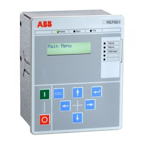
Section 5 1MDU07212-YN Rev. C Use of LHMI Section 5 Use of LHMI Overview Figure 10: Local HMI of relay REF601/REJ601 The local HMI of the relay contains following elements: · LED indicators · LCD display · Navigation buttons / keys The LHMI is used for setting, monitoring and controlling. - Page 45 LHMI as well to reset trip LEDs Edit Press key Enter to edit the relay parameter from LHMI Breaker Close Hotkey for providing Breaker Close command. Breaker Open Hotkey for providing Breaker Open command. REF601 / REJ601 Application Manual...
-
Page 46: Authorization
Password needs to be entered here as indicated in Sr. no. 7 in case it is configured as Simple password and should be as indicated in Sr. no. 8 in case it is configured as alpha-numerical password. REF601 / REJ601 Application Manual... -
Page 47: Configuration Status
The selected category will pop up for one second before the main menu is shown. Sequence looks as follow: Figure 11: Login process of relay REF601 / REJ601 Password configuration The password could be changed under the Main Menu -> Access Level. -
Page 48: Lhmi Menu Navigation
Current values are displayed in this view for phase current and earth current in “A” as shown in following figure. Figure 14: Default screen of relay REF601 / REJ601 5.2.2 Main menu The main menu appears after entering the password with the user rights depended on the entered password. -
Page 49: Menu - Measurement
1 – HIGH 0 – Open BO Status 123456 1 – Close Status 000100 Counter Count :XXXXX OPTS RunTime:XXXXXhrs Note * - only available when respective function in IED configuration Figure 16: Measurement menu of relay REF601/REJ601 REF601 / REJ601 Application Manual... -
Page 50: Menu - Fault Record
For viewing the user should follow the figure below. Figure 17: Fault record data menu of relay REF601/REJ601 5.2.5 Menu - Events Submenu Events shows events 1 –... -
Page 51: Menu - Setting
Following menu structure is used to navigate to the respective settings: Following menu structure is used to navigate to the respective settings: Following menu structure is used to navigate to the respective settings: REF601 / REJ601 REF601 / REJ601 REF601 / REJ601... - Page 52 Section 5 1MDU07212-YN Rev. C Use of LHMI Figure 19: Setting menu of relay REF601/REJ601 with its submenu REF601 / REJ601 Application Manual...
-
Page 53: Menu - Configuration
To modify selected setting start with key · To save changed setting with key · To discard and exit a modified setting with key Following menu structure is used to navigate to the respective configuration settings: REF601 / REJ601 Application Manual... - Page 54 Section 5 1MDU07212-YN Rev. C Use of LHMI REF601 / REJ601 Application Manual...
- Page 55 Section 5 1MDU07212-YN Rev. C Use of LHMI REF601 / REJ601 Application Manual...
- Page 56 Protection Reset NO; YES Clock Settings Date Settings DD/MM/YYYY Time Settings HH:MM:SS TRIP Circuit NO; YES Supervision- TCS Block TCS Operate 001 … 300 Time:XXX Sec Figure 20: Configuration menu of relay REF601/REJ601 with its submenu REF601 / REJ601 Application Manual...
-
Page 57: Menu - Test
Remark: To modify settings needs user rights of Setting or Admin user. Following menu structure is used to navigate to the respective test settings: Figure 21: Test menu of relay REF601/REJ601 with its submenu REF601 / REJ601 Application Manual... - Page 58 5 sec timeout test sequence will move to next screen. Each test procedure provides test result messages and interactive user selections on LCD. Figure 22: Hardware test menu of relay REF601/REJ601 with its submenu REF601 / REJ601 Application Manual...
- Page 59 Section 5 1MDU07212-YN Rev. C Use of LHMI Figure 23: Hardware test menu of relay REF601/REJ601 with its submenu (Continue) REF601 / REJ601 Application Manual...
- Page 60 Submenu – Binary output test Submenu binary output test allows to force a binary output. The forced output operates for a pulse duration of 1 sec. Figure 24: Binary output test menu of relay REF601/REJ601 with its submenu (Continue) REF601 / REJ601 Application Manual...
-
Page 61: Access Level
Submenu – Functional test Submenu functional test allows performing simulation of each protection function by giving a test current to the selected protection function. Figure 25: Functional test menu of relay REF601/REJ601 5.2.9 Access level This menu provides the password change facility for the different access levels. -
Page 62: Version Information
This menu provides information regarding the Product type selected, Software version being presently loaded into the product, Model name, Nominal current value selected, and the type of trip circuit present. Figure 27: Version information menu REF601 / REJ601 Application Manual... -
Page 63: Installation
Check the relay for transport damages. If the product has been damaged, a claim should be made to the transport contractor and the local representative of ABB should be promptly notified. Compare the type designation of the product with the ordering information to verify that you have received the right product. -
Page 64: Relay Wiring
: 151.5 ± 0.5 x 121.5 ± 0.5 mm Depth behind the panel : 151.5 mm for CT variant : 101.5 mm for Sensor variant Weight : 1.43 kg for CT variant : 1.20 kg for Sensor variant REF601 / REJ601 Application Manual... - Page 65 Section 6 1MDU07212-YN Rev. C Installation Figure 28: Overall mounting dimension of REF601/REJ601 with CT variant Figure 29: Overall mounting dimension of REF601/REJ601 with Sensor variant REF601 / REJ601 Application Manual...
- Page 66 Panel mounting details of Panel mounting details of Panel mounting details of Panel mounting details of Panel mounting details of Panel mounting details of Panel mounting details of Panel mounting details of REF601/REJ601 REF601/REJ601 REF601/REJ601 REF601/REJ601 REF601/REJ601 REF601/REJ601 REF601 / REJ601...
-
Page 67: Terminal Diagram
1MDU07212-YN Rev. C Installation Terminal diagram Relay terminal / connection diagram for both conventional CT as well sensor variant shall be as the relay. Figure 31: Connection diagram of relay REF601 /REJ601 with CT variant REF601 / REJ601 Application Manual... - Page 68 Section 6 1MDU07212-YN Rev. C Installation Figure 32: Connection diagram of relay REF601 /REJ601 with Sensor variant REF601 / REJ601 Application Manual...
-
Page 69: Relay Ordering Information
Configuration 2 Configuration 3 Configuration 4 Power supply 24...240V AC / DC Configuration Ring lug terminals Screw terminals Version Product version 2.2 FP1 Digit (#) Your Order Code Figure 33: Ordering information of relay REF601/REJ601 REF601 / REJ601 Application Manual... -
Page 70: Accessories And Ordering Data
Section 6 1MDU07212-YN Rev. C Installation Accessories and ordering data Table 28: REF601/REJ601 accessories and ordering data Item Order number RE_601 communication card CIM601BNNNNBANXH REF601 / REJ601 Application Manual... -
Page 71: Setting Table
30%...50%, I2> / 46 I2> 0.30 0.1…1.5 0.010 tI2> 1.00 0.1 … 300 0.100 0=No block protn 1=Yes I2/I1> / 46PD I2/I1> 015% 10…100% 0.010 tI2/I1> 00.10 0.1 … 64 0.100 0=No block protn 1=Yes REF601 / REJ601 Application Manual... - Page 72 1 = OCO, 2 = CO Shot 0…4 Activate t 0.1…5 0.100 Pulse tp 0.2…20 0.100 Cycle t1 0.2…300 0.010 Cycle t2 0.2…300 0.010 Cycle t3 0.2…300 0.010 Cycle t4 0.2…300 0.010 Reclaim tr 1…300 Block tb 1…300 REF601 / REJ601 Application Manual...
- Page 73 IEC_103: 9600; 19200 MODBUS: 001 … 247 Relay Addr IEC_103: 001…254 MODBUS: None; Odd; Even Comm. Parity Even IEC_103: None; Even Class2 Intv (IEC_103) 0…60 sec Class2 SF 1.2; 2.4 Comm Admin Level NO; YES REF601 / REJ601 Application Manual...
- Page 74 Signal to activate output Output behavior: inversion Output behavior: duration Start : I> / 51 Start : I>> / 50-1 Start : I>>> / 50-2 Start : Io> / 50N-1 Start : Io>> / 50N-2 REF601 / REJ601 Application Manual...
- Page 75 O->I FinalTr O->I Blocked Signal 1 Signal 2 Signal 3 CB Open Command CB Close Command TCS Fault Unit Ready Output behavior : “-“ = Non inverted, “I” = Inverted Remark : “(..)” = Default setting REF601 / REJ601 Application Manual...
- Page 76 Trip : Io>> / 50N-2 3Ith> Alm 3Ith> BlkCl I2/I1> Str I2/I1> Tr I2> Start I2> Trip BF Stage1 BF Stage2 BF RecTrip O->I Close O->I InPro O->I FinalTr O->I Blocked Signal 1 Signal 2 Signal 3 TCS Fault REF601 / REJ601 Application Manual...
-
Page 77: Earthing Of Relay And Bonding Of Sensor Cable Shield
M4 screw lug to fit under the M4 screw lug to fit under the M4 screw lug to fit under the M4 screw. REF601 / REJ601 REF601 / REJ601 REF601 / REJ601 REF601 / REJ601... -
Page 78: Shield Connection At Relay Side (Sensor Variant)
This shall result in a better connection of the sensor cable shield to the chassis respect to ground. Figure 35: Shields connection at relay side · In case of breaker mounting metal strip can be mounted at the rear of the relay on metal plate. REF601 / REJ601 Application Manual... - Page 79 ABB Limited Distribution Automation Maneja Vadodara 390013, India Phone +91 265 2604032 Fax +91 265 2638922 ABB Oy Distribution Automation P.O. Box 699 FI-65101 VAASA, Finland Phone +358 10 22 11 Fax +358 10 22 41094 www.abb.com/substationautomation...