ABB REF601 Applications Manual
Feeder protection and control/feeder protection
Hide thumbs
Also See for REF601:
- Applications manual (79 pages) ,
- Product manual (22 pages) ,
- Applications manual (90 pages)

Related Manuals for ABB REF601


Summary of Contents for ABB REF601
- Page 1 Relion 605 series ® Feeder protection and control / Relion 605 series ® Relion 605 series ® Feeder protection REF601 / REJ601 Application manual...
- Page 3 Document ID: 1MDU07212-YN Issued: 2012-09-28 Revision: revision: A Product version: 2.1 © Copyright 2012 ABB. All rights reserved...
- Page 4 Copyright This document and parts thereof must not be reproduced or copied without written permission from ABB, and the contents thereof must not be imparted to a third party, nor used for any unauthorized purpose. The software or hardware described in this document is furnished under a license and may be used, copied, or disclosed only in accordance with the terms of such license.
- Page 5 In case any errors are detected, the reader is kindly requested to notify the manufacturer. Other than under explicit contractual commitments, in no event shall ABB be responsible or liable for any loss or damage resulting from the use of this manual or the application of the equipment.
- Page 6 (EMC Directive 2004/108/EC) and concerning electrical equipment for use within specified voltage limits (Low-voltage directive 2006/95/EC). This conformity is the result of tests conducted by ABB in accordance with the product standards EN 50263 and EN 60255-26 for the EMC directive, and with the product standards EN 60255-1 and EN 60255-27 for the low voltage directive.
-
Page 7: Table Of Contents
This manual ....................5 Intended audience ..................5 Document revision history ................5 Document symbol and conventions ............. 6 Section 2 REF601/REJ601 overview ........7 Overview ....................7 Product version history ................7 Operation functionality ................8 2.3.1 Relay functions ..................8 2.3.2 Optional function .................. - Page 8 LHMI menu navigation ................26 5.2.1 Default screen ..................26 5.2.2 Main menu....................27 5.2.3 Menu – Measurement ................28 5.2.4 Menu – Recorded data ................29 5.2.5 Menu - Events ..................29 5.2.6 Menu – Setting..................30 5.2.7 Menu – Configuration ................32 REF601 / REJ601 Application Manual...
- Page 9 Storage..................... 42 Checking environmental condition and mounting space ......42 Relay wiring ....................43 Relay mounting and dimensions ............... 43 Relay ordering information ................ 46 Accessories and ordering data ..............46 ................... 46 Setting table REF601 / REJ601 Application Manual...
-
Page 11: General
The manual contains terms and expressions commonly used to describe this kind of equipment. Document revision history Document Product version Document history revision/date Release of REF601/REJ601 with A / 28.09.2012 conventional current transformer REF601 / REJ601 Application Manual... -
Page 12: Document Symbol And Conventions
The tip icon indicates advice on, for example, how to design your project or how to use a certain function. REF601 / REJ601 Application Manual... -
Page 13: Ref601/Rej601 Overview
ABB’s in-depth knowledge of protection and numerical technology. The REF601/REJ601 features compact size and ease of use. The features include: Standard 1A or 5A CT input for phase current measurement... -
Page 14: Operation Functionality
REF601/REJ601 overview Operation Functionality 2.3.1 Relay functions REF601/REJ601 offers pre-configured functionality which facilitates easy and fast commissioning of switchgear. To emphasize the simplicity of relay’s usage, only application specific parameters needs to set within the relay’s intended area of application. -
Page 15: Other Functions
Runtime “EEPROM“ check fault IRF 064 Gain check fault The user can try to eliminate the fault by restarting the IED. If the fault is found to be permanent, the IED stays in internal fault mode. REF601 / REJ601 Application Manual... -
Page 16: Fault Record And Trip Counter
The event logs are stored sequentially, the most recent being first and so on. The SoE information are accessible locally via LHMI and remotely via communication interface of the relay. REF601 / REJ601 Application Manual... -
Page 17: Real Time Clock
. In case of power failure RTC will have a stored energy backup for around 48 hrs. at ambient temperature when stored energy element is fully charged. Initial time setting is “01/01/2011” and “00:00:00:000”. REF601 / REJ601 Application Manual... -
Page 18: Access Control
The password is a combination of different navigation keys. 2.4.6 Power-ON sequence The Power-ON sequence takes around 6 sec. In case the optional communication on MODBUS is present, the startup time takes around 40 sec. REF601 / REJ601 Application Manual... -
Page 19: Technical Data
Normal inverse, Very inverse, Extremely inverse, Long-time inverse Operating curve type (IDMT) Special curves: RI inverse Time multiplier setting k (IDMT) 0.05, 0.1...1.6, in steps of 0.1 Reset ratio IDMT : 0.96 and DT : 0.98 Reset time REF601 / REJ601 Application Manual... -
Page 20: Earth Fault Protection
“Trip” and “Trip Io” will be activated. Additional the output relays (Trip and signalization) will be activated according the binary output configuration. Each of the stages could be blocked by settings or via binary input of the relay. REF601 / REJ601 Application Manual... -
Page 21: Setting Range Of Earth Fault Overcurrent Protection
When an inrush case is detected, the phase overcurrent and earth fault protection functions are immediately blocked. Table 9: Setting ranges Transformer inrush detector Description Value Inrush threshold value 0.2...20 x In Ratio Setting 30%...50% REF601 / REJ601 Application Manual... -
Page 22: Protection Characteristics
The slope of the time/current characteristics shall be determined by the constants and ß as indicated below: Table 10: Values of constant Slope of the time/current curve set Normal inverse 0.02 0.14 Very inverse 13.5 Extremely inverse Long time inverse REF601 / REJ601 Application Manual... -
Page 23: Ri Type Characteristic
Output can be reset only by local HMI by reset key combination and Reset binary input. All above mode also supports Inverted (I) operation. Operating mode for binary output BO4 is fixed to “Inverted Self- Reset Mode.” REF601 / REJ601 Application Manual... -
Page 24: Configurable Binary Inputs
2. Circuit Breaker Status: Binary inputs BI2 to BI4 can be configured to indicate the status of circuit breaker i.e. breaker open or breaker close or breaker in maintenance. The available status information is sent to MODBUS communication. REF601 / REJ601 Application Manual... -
Page 25: Breaker Control And Trip Command Operation
It is possible to enable/disable TCS functionality through configuration parameter. For the TCS functionality the BI2 need to be connected in parallel to the trip output BO2 as shown in the figure below. Additional the BI2 need to be configured for the TCS functionally. REF601 / REJ601 Application Manual... - Page 26 Otherwise, TCS sees a faulty trip circuit in open circuit breaker position. Table 12: TCS functionality parameters and selection range Name Value (Range) Unit Step Default Description 1…10 Operate delay time Settable 10…300 Reset delay time Fixed REF601 / REJ601 Application Manual...
-
Page 27: Signal Diagram
Signal Diagram The figure below schematically illustrates the analogue input, binary input / output and LED indications. Figure 4: Signal diagram of relay REF601/REJ601 Table 13: Analog inputs L1, L2, L3 Current transformer input for phase L1, L2, L3 , either 1A or 5A according to order type. - Page 28 Default as signaling contact over current trip. In the event of phase faults (I>, I>> and I >>>) it will close and remain latched Default as signaling contact earth fault trip. In the event of earth faults (Io> and Io>> it will close and remain latched REF601 / REJ601 Application Manual...
-
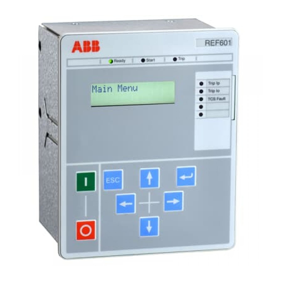
Page 29: Use Of Lhmi
Use of LHMI Section 5 Use of LHMI Overview Figure 5: Local HMI of relay REF601/REJ601 The local HMI of the relay contains following elements: LED indicators LCD display Navigation buttons / keys The LHMI is used for setting, monitoring and controlling. -
Page 30: Lcd Display
LHMI Press key combination Enter and Escape key together to Edit edit the relay parameter from LHMI Breaker Close Hotkey for providing Breaker Close command. Breaker Open Hotkey for providing Breaker Open command. REF601 / REJ601 Application Manual... -
Page 31: Authorization
1MDU07212-YN Rev. A Use of LHMI 5.1.4 Authorization Within REF601/REJ601 three user categories with predefined user rights are provided. During access of the main menu the selection of user category is handled with an own password (two key combinations). The rights per user category and their default password are listed in following... -
Page 32: Configuration Status
Current values are displayed in this view for phase current in “Amp” and for earth current in “In” as shown in following figure. Figure 8: Default screen of relay REF601 / REJ601 REF601 / REJ601 Application Manual... -
Page 33: Main Menu
Main menu The main menu appears after entering the password with the user rights depended on the entered password. Following view shows the main menu of the relay. Figure 9: Main menu of relay REF601/REJ601 REF601 / REJ601 Application Manual... -
Page 34: Menu - Measurement
– settings. Also it shows binary input and output status at the relay terminal. Figure 10: Measurement menu of relay REF601/REJ601 REF601 / REJ601 Application Manual... -
Page 35: Menu - Recorded Data
For viewing the user should follow the figure below. Figure 11: Fault record data menu of relay REF601/REJ601 5.2.5 Menu - Events Submenu Events shows events 1 –... -
Page 36: Menu - Setting
If COM Admin Level is YES, then IED configuration parameter is allowed to change through MODBUS Following menu structure is used to navigate to the respective settings: REF601 / REJ601 Application Manual... - Page 37 :XX.XX :XX.XX I0>> I0>> I0>> :XX.XXX In I0>> t0>> :XX.XX COM Parameters COM Parameters Baud Rate :XXXXX COM Parameters Relay Addr:XXX COM Parameters Parity :XXXX Figure 13: Setting menu of relay REF601/REJ601 with its submenu REF601 / REJ601 Application Manual...
-
Page 38: Menu - Configuration
To modify selected setting start with key combination To save changed setting with key To discard and exit a modified setting with key Following menu structure is used to navigate to the respective configuration settings: REF601 / REJ601 Application Manual... - Page 39 Section 5 1MDU07212-YN Rev. A Use of LHMI REF601 / REJ601 Application Manual...
- Page 40 Section 5 1MDU07212-YN Rev. A Use of LHMI REF601 / REJ601 Application Manual...
- Page 41 Protection Reset NO; YES Clock Settings Date Settings DD/MM/YYYY Time Settings HH:MM:SS TRIP Circuit NO; YES Supervision- TCS Block TCS Operate 001 … 300 Time:XXX Sec Figure 14: Configuration menu of relay REF601/REJ601 with its submenu REF601 / REJ601 Application Manual...
-
Page 42: Menu - Test
To modify settings needs user rights of Setting or Admin user. Following menu structure is used to navigate to the respective test settings: Test Test Hardware :YYY Test Test Functional Figure 15: Test menu of relay REF601/REJ601 with its submenu REF601 / REJ601 Application Manual... - Page 43 Each test procedure provides test result messages and interactive user selections on LCD. LCD TEST LCD TEST LCD TEST LCD Test LCD TEST Test Continue Test Continue YES:UP NO:DOWN YES:UP NO:DOWN Figure 16: Hardware test menu of relay REF601/REJ601 with its submenu REF601 / REJ601 Application Manual...
- Page 44 Section 5 1MDU07212-YN Rev. A Use of LHMI Figure 17: Hardware test menu of relay REF601/REJ601 with its submenu (Continue) REF601 / REJ601 Application Manual...
- Page 45 Submenu – Binary output test Submenu binary output test allows to force a binary output. The forced output operates for a pulse duration of 1 sec. Figure 18: Binary output test menu of relay REF601/REJ601 with its submenu (Continue) REF601 / REJ601 Application Manual...
-
Page 46: Access Level
Functional Test NO; YES I0>> :YYY Figure 19: Functional test menu of relay REF601/REJ601 5.2.9 Access level This menu provides the password change facility for the different access levels. Only Admin can change the password of the other access levels. Activating edit mode by pressing Enter and Cancel button together can change password. -
Page 47: Version Information
This menu provides information regarding the Product type selected, Software version being presently loaded into the product, Model name, Nominal current value selected, and the type of trip circuit present. Figure 21: Version information menu REF601 / REJ601 Application Manual... -
Page 48: Installation
Check the relay for transport damages. If the product has been damaged, a claim should be made to the transport contractor and the local representative of ABB should be promptly notified. Compare the type designation of the product with the ordering information to verify that you have received the right product. -
Page 49: Relay Wiring
: 160 x 130 x 151.1 mm Cutout dimensions (H x W) : 152 ± 0.5 x 122 ± 0.5 mm Depth behind the panel : 148.5 mm Weight : 1.43 kg Figure 22: Overall mounting dimension of REF601/REJ601 REF601 / REJ601 Application Manual... - Page 50 Section 6 1MDU07212-YN Rev. A Installation Panel door Press fit mechanism 152 ± 0.5 Figure 23: Panel mounting details of REF601/REJ601 REF601 / REJ601 Application Manual...
- Page 51 Section 6 1MDU07212-YN Rev. A Installation Relay connection diagram Figure 24: Connection diagram of relay REF601 /REJ601 REF601 / REJ601 Application Manual...
-
Page 52: Relay Ordering Information
For future use Undefined Version Product version 2.1 Digit (#) 10 11 Your Order Code Figure 25: Ordering information of relay REF601/REJ601 Accessories and ordering data Table 19: REF601/REJ601 accessories and ordering data Item Order number RE_601 communication card CIM601BNNNNBANXF... -
Page 53: Setting Table
20 … 9999 CT Isn 1; 5 Frequency 50; 60 2400; 4800; 9600; Comm. Baud Rate 19200 19200; 38400 Comm. Relay Addr 001 … 247 Comm. Parity None None; Odd; Even Comm Admin Level NO; YES REF601 / REJ601 Application Manual... - Page 54 Trip : Io> / 51N Trip : Io> / 50N CB Open Command CB Close Command TCS Fault Unit Ready Output behavior : (-) – Non inverted, (I) – Inverted Remark : (..) = Default setting REF601 / REJ601 Application Manual...
- Page 56 Contact us ABB Ltd, Distribution Automation Maneja Works Vadodara-390013, India Phone: +91 265 2604386 Fax: +91 265 2638922 www.abb.com/substationautomation...