
Related Manuals for Fujitsu MB2147-01


Summary of Contents for Fujitsu MB2147-01
- Page 1 How to Install/Update USB Driver for the Fujitsu MB2147-01 and MB2198-01 Emulator System Application Note Confidential...
-
Page 2: Table Of Contents
Difference from the Previous USB Driver Version ........................1 USB Driver Uninstallation Procedure ............................2 USB Driver Installation Procedure ............................3 Driver Confirmation ................................3 USB Driver Installation from Found New Hardware Wizard......................4 Restoring the Previous Driver ..............................4 Common USB Driver Errors and Possible Solutions ........................5 Fujitsu Microelectronics America, Inc. -
Page 3: Introduction
The Fujitsu emulator systems are required to perform complex 2. The driver file name is “ windrvr6.sys ” and its version is “ 7.02 ”. debugging of test code on target systems. The Fujitsu emulator systems provides complex debugging functions such as Watch and Trace to help the user debug the software through communication that exists between IDE (SW) and the emulator system (HW). -
Page 4: Usb Driver Uninstallation Procedure
Note: When the above description is not displayed, install the driver without taking any measures. USB Driver Uninstallation Procedure • Right click on the [FUJITSU USB Driver for ICE] and click “Uninstall”. It is required to uninstall the previous USB driver before installing the USB driver version 9.01. -
Page 5: Usb Driver Installation Procedure
Now the installation of the USB driver is completed. Driver Confirmation To confirm whether USB driver is correctly installed by the above procedures, check the driver file “ windrvr6.sys ” in the detailed dialog of [USB]-[ FUJITSU USB Driver for ICE] of Device manager. Fujitsu Microelectronics America, Inc. -
Page 6: Usb Driver Installation From Found New Hardware Wizard
It has been observed that in some cases, even though the USB driver performed. In this case, use the USB driver package “ WinDriver has been installed, it is not recognize by the PC when the Fujitsu ver-7.02” or earlier. The procedure is shown as follows. -
Page 7: Common Usb Driver Errors And Possible Solutions
Windows system. though the driver has been already installed before. To avoid the reinstallation again, try power ON/OFF sequence or switch the USB port on PC. If the above problem still persists then contact Fujitsu Support, mcugroup@fma.fujitsu.com Fujitsu Microelectronics America, Inc. - Page 8 FUJITSU MICROELECTRONICS AMERICA, INC. ©2008 Fujitsu Microelectronics America, Inc. All rights reserved. All company and product names are trademarks or registered Corporate Headquarters trademarks of their respective owners. 1250 East Arques Avenue, M/S 333, Sunnyvale, California 94085-5401 Printed in U.S.A. MCU-AN-21299-4/2008 Tel: (800) 866-8608 Fax: (408) 737-5999 E-mail: inquiry@fma.fujitsu.com Web Site: http://us.fujitsu.com/micro...
- Page 9 CM71-00413-2E FUJITSU SEMICONDUCTOR CONTROLLER MANUAL DSU-FR EMULATOR MB2198-01 HARDWARE MANUAL...
- Page 11 DSU-FR EMULATOR MB2198-01 HARDWARE MANUAL FUJITSU LIMITED...
- Page 13 FR family. This manual is intended for engineers who use the MB2198-01 (hereafter called the emulator) to develop application products with Fujitsu FR-family microcontrollers. The manual explains how to handle and connect the emulator.
- Page 14 I Safety Precautions The following tables contain descriptions of important warnings in this manual and indicate the pages on which they appear. Before using the product, read these pages so that you fully understand the requirements for safe use of the product. This symbol indicates that incorrect use of the product may result in death WARNING or serious injury to the user.
- Page 15 This symbol indicates that incorrect use of the product may result in death WARNING or serious injury to the user. Warning Description Page Do not touch the product with wet hands. Doing so may result in electric shock. Prohibition Do not place the product in a location exposed to excessive moisture or dust or in a poorly ventilated location.
- Page 16 This symbol indicates that incorrect use of the product may result in minor or CAUTION moderate injury to the user, in damage to the product and any devices connected to it, or in the destruction of data and other software resources or other property.
- Page 17 This symbol indicates that incorrect use of the product may result in minor or CAUTION moderate injury to the user, in damage to the product and any devices connected to it, or in the destruction of data and other software resources or other property.
- Page 18 I Organization of This Manual This manual consists of three chapters. Read the manual thoroughly before using the emulator. CHAPTER 1 PRODUCT HANDLING AND SPECIFICATIONS This chapter explains handling of the emulator and gives its specifications. Before using the emulator, read this chapter thoroughly and be sure that you understand the information about the product.
- Page 19 (2) for use requiring extremely high reliability (i.e., submersible repeater and artificial satellite). Please note that Fujitsu will not be liable against you and/or any third party for any claims or damages arising in connection with above-mentioned uses of the products.
- Page 20 viii...
- Page 21 CONTENTS CHAPTER 1 PRODUCT HANDLING AND SPECIFICATIONS ......... 1 Checking Packed Components ......................2 Appearance and Part Names ........................ 3 General Specifications ........................... 5 RS-232C Port Specifications ......................... 6 USB Port Specifications ......................... 7 LAN Port Specifications ......................... 8 External Trigger Input Terminal Specifications ..................9 Program Execution Output Terminal Specifications ................
-
Page 23: Chapter 1 Product Handling And Specifications
CHAPTER 1 PRODUCT HANDLING AND SPECIFICATIONS This chapter explains handling of the emulator and gives its specifications. Before using the emulator, read this chapter thoroughly and be sure that you understand the information about the product. 1.1 "Checking Packed Components" 1.2 "Appearance and Part Names"... -
Page 24: Checking Packed Components
CHAPTER 1 PRODUCT HANDLING AND SPECIFICATIONS Checking Packed Components Before using the emulator, check the packed components to make sure that all components have been delivered. I Checking Packed Components CAUTION To re-transport the product, use the package used at the delivery, and Attention pack them as it was packed. -
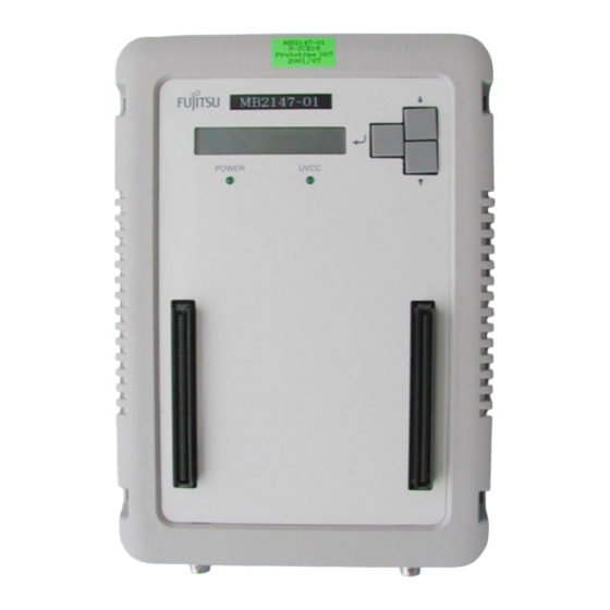
Page 25: Appearance And Part Names
1.2 Appearance and Part Names Appearance and Part Names This section describes parts on the outside of the emulator and gives their names. For information on connecting the emulator, see Chapter 2 "CONNECTION METHOD". I Appearance and Part Names Figure 1.2-1 "Emulator Appearance (top view)" to Figure 1.2-3 "Emulator Appearance (rear view)"... - Page 26 CHAPTER 1 PRODUCT HANDLING AND SPECIFICATIONS Figure 1.2-2 Emulator Appearance (front view) Name Description DSU-FR cable connector Connector for a DSU-FR cable Terminal used for input of external trigger signals TRIG terminal Terminal that outputs program execution signals EMUL terminal Figure 1.2-3 Emulator Appearance (rear view) Description Name...
-
Page 27: General Specifications
1.3 General Specifications General Specifications Table 1.3-1 "General Specifications of Emulator" lists the general specifications of the emulator. I General Specifications of Emulator CAUTION Use the product according to its specifications. Doing so may result in Caution device problems. Table 1.3-1 General Specifications of Emulator Item Specification Name... -
Page 28: Rs-232C Port Specifications
CHAPTER 1 PRODUCT HANDLING AND SPECIFICATIONS RS-232C Port Specifications The emulator can be connected to one RS-232C cable. I RS-232C Port Specifications Table 1.4-1 "RS-232C Port Specifications" lists the RS-232C port specifications. Figure 1.4-1 "RS-232C Connector Circuit Configuration" shows the connector circuit configuration. For information on Interlink cable connection, see Section 1.10 "Options". -
Page 29: Usb Port Specifications
1.5 USB Port Specifications USB Port Specifications The emulator can be connected to one USB cable. I USB Port Specifications Table 1.5-1 "USB Port Specifications" lists the USB port specifications. Table 1.5-1 USB Port Specifications Item Description Applicable standard USB 1.1 Communication protocol Full Speed Bulk Transfer Data transfer rate... -
Page 30: Lan Port Specifications
CHAPTER 1 PRODUCT HANDLING AND SPECIFICATIONS LAN Port Specifications The emulator can be connected to one LAN cable. I LAN Port Specifications Table 1.6-1 "LAN Port Specifications" lists the LAN port specifications. Table 1.6-1 LAN Port Specifications Item Description Applicable standard IEEE 802.3 Communication protocol TCP/IP... -
Page 31: External Trigger Input Terminal Specifications
1.7 External Trigger Input Terminal Specifications External Trigger Input Terminal Specifications The emulator has the TRIG terminal that is used as a input terminal for external trigger signals. I External Trigger Input Terminal Specifications The external trigger input terminal is a part that connects a logic analyzer or other such external device to the emulator. -
Page 32: Program Execution Output Terminal Specifications
CHAPTER 1 PRODUCT HANDLING AND SPECIFICATIONS Program Execution Output Terminal Specifications The emulator has the EMUL terminal that is used as an output terminal for program execution signals I Program Execution Output Terminal Specifications The program execution output terminal is used to execute user programs. Table 1.8-1 "Program Execution Output Terminal Specifications"... -
Page 33: Power-On Debug Specifications
Fujitsu Sales Dept. or Support Dept. *2 The name of the reset terminal may depend on the model of the evaluation MCU. For more information, contact the Fujitsu Sales Dept. or Support Dept. I Operation Flow Figure 1.9-1 "Power-on Debug Operation Flow" shows the flow of the power-on debug operation. - Page 34 CHAPTER 1 PRODUCT HANDLING AND SPECIFICATIONS I Operation Overview Figure 1.9-2 "Timing of Power-on Debug Operation" is a timing chart of the power-on debug operation. In this example, the reset terminal name is assumed to be "INIT". [Operation timing] Power-off detection: The power-off status of user system power (UV ) voltage is detected.
-
Page 35: Options
Several types of this cable may be released in the future. Select and purchase a DSU-FR cable that is compatible with both the emulator and the user system. For information on selecting a suitable DSU-FR cable, contact the Fujitsu Sales Dept. or Support Dept. - Page 36 CHAPTER 1 PRODUCT HANDLING AND SPECIFICATIONS Figure 1.10-1 Interlink Cable Wiring Personal computer side Emulator side D-sub 9-pin D-sub 9-pin female connector female connector (DCD) 1 1 (DCD) (RXD) 2 2 (RXD) 3 (TXD) (TXD) 3 (DTR) 4 4 (DTR) (GND) 5 5 (GND) (DSR) 6...
-
Page 37: Precautions On Possible Problems
1.11 Precautions on Possible Problems 1.11 Precautions on Possible Problems Take the following precautions for problems that may occur while you are using the emulator. I Precautions on Possible Problems WARNING If the product emits excessive heat, smoke, an offensive smell, or an Plug unusual noise, turn off power immediately. -
Page 38: Precautions On Handling The Emulator
CHAPTER 1 PRODUCT HANDLING AND SPECIFICATIONS 1.12 Precautions on Handling the Emulator Take the following precautions on handling the emulator. I Precautions on Handling the Emulator WARNING Do not touch the inside of a connector port. Doing so may result in Electric shock electric shock or device problems. - Page 39 1.12 Precautions on Handling the Emulator WARNING Do not touch the product with wet hands. Doing so may result in Prohibition electric shock. Do not place the product in a location exposed to excessive moisture or dust or in a poorly ventilated location. Do not place the product near an open flame.
- Page 40 CHAPTER 1 PRODUCT HANDLING AND SPECIFICATIONS CAUTION Disconnect the power plug before moving the product. Disconnect all Plug other connected cables. Exercise caution when working near cables on the floor. Damage to a cable may result in fire or electric shock. A falling device may result in injury.
-
Page 41: Precautions On Use
1.13 Precautions on Use 1.13 Precautions on Use Take the following precautions on using the emulator. I Precautions on Use WARNING Do not block the product ventilation holes. Doing so may cause Prohibition generation of excessive heat, possibly resulting in a fire. Do not use the product if it has a fault, damage, or sever wires in the cable. - Page 42 CHAPTER 1 PRODUCT HANDLING AND SPECIFICATIONS I Precautions on Storage CAUTION Do not apply any shock to this product. Doing so may result in device Prohibition problems. Do not expose the product to direct sunlight, and do not place it where it is hot and humid.
-
Page 43: Chapter 2 Connection Method
CHAPTER 2 CONNECTION METHOD This chapter explains how to connect the emulator. Read this chapter thoroughly before powering on the emulator. 2.1 "System Configuration" 2.2 "Connection of DSU-FR Cable to Attached Cable" 2.3 "Connection of User System" 2.4 "Connection of DSU-FR Cable" 2.5 "Connection of Adapter Board"... -
Page 44: System Configuration
CHAPTER 2 CONNECTION METHOD System Configuration The emulator is designed to be connected to and controlled from a host machine. The host machine uses emulator debugger software to control the emulator. For information on using the software, see the Softune Workbench Operation Manual. I System Configuration Figure 2.1-1 "System Configuration (if a DSU-FR cable is used)"... -
Page 45: Connection Of Dsu-Fr Cable To Attached Cable
2.2 Connection of DSU-FR Cable to Attached Cable Connection of DSU-FR Cable to Attached Cable Connect an attached cable (FPC or flat cable) to a DSU-FR cable as shown in Figure 2.2-1 "Connection of DSU-FR Cable to FPC Cable (DSU-3)" and Figure 2.2-2 "Connection of DSU-FR Cable to Flat Cable (DSU-4)". - Page 46 CHAPTER 2 CONNECTION METHOD I Connection of DSU-FR Cable to FPC Cable (for DSU-3) CAUTION Make sure that power to the product is turned off and the power plug is Prohibition disconnected from outlets before connecting or disconnecting cables. Doing so may result in device problems or electric shock. Grasp connectors when connecting or disconnecting a cable.
- Page 47 2.2 Connection of DSU-FR Cable to Attached Cable I Connection of DSU-FR Cable to Flat Cable (for DSU-4) CAUTION Make sure that power to the product is turned off and the power plug is Prohibition disconnected from outlets before connecting or disconnecting cables. Doing so may result in device problems or electric shock.
-
Page 48: Connection Of User System
CHAPTER 2 CONNECTION METHOD Connection of User System Connect a DSU-FR cable to the emulator interface connector on the user system as shown in Figure 2.3-1 "Connection of User System (DSU-3)" or Figure 2.3-2 "Connection of User System (DSU-4)". For the emulator interface connector specifications, see Appendix B "User System Specifications". - Page 49 2.3 Connection of User System Figure 2.3-1 Connection of User System (DSU-3) User system connector Movable part Emulator interface connector ser system To connect the DSU-FR cable, pull out the movable part (white part) below the emulator interface connector on the user system, insert the user system connector, and then push the movable part back in place.
- Page 50 CHAPTER 2 CONNECTION METHOD I Connection of User System (for DSU-4) CAUTION Make sure that power to the product is turned off and the power plug is Prohibition disconnected from outlets before connecting or disconnecting cables. Doing so may result in device problems or electric shock. Grasp connectors when connecting or disconnecting a cable.
-
Page 51: Connection Of Dsu-Fr Cable
2.4 Connection of DSU-FR Cable Connection of DSU-FR Cable Connect a DSU-FR cable to the DSU-FR cable connector on the front of the emulator as shown in Figure 2.4-1 "Connection of DSU-FR Cable". For the DSU-FR cable specifications, see Appendix A "DSU-FR Cable Specifications". I Connection of DSU-FR Cable CAUTION Make sure that power to the product is turned off and the power plug is... -
Page 52: Connection Of Adapter Board
CHAPTER 2 CONNECTION METHOD Connection of Adapter Board Connect an adapter board (option) to the adapter board connector on the top of the emulator. Use a header board to connect the adapter board to the user system. For information on connecting an adapter board to the user system, see the hardware manual of the adapter board. -
Page 53: Connection Of Host Machine
2.6 Connection of Host Machine Connection of Host Machine Connect a host machine to the emulator through an RS-232C cable, USB cable, or LAN cable as shown in Figure 2.6-1 "Connection of Host Machine". To connect a plug-and-play device through a USB cable to the host machine, first turn on the power to all devices, and then connect the USB cable to the host machine. -
Page 54: Connection Of Ac Adapter
CHAPTER 2 CONNECTION METHOD Connection of AC Adapter Connect the AC adapter to the emulator as shown in Figure 2.7-1 "Connection of AC Adapter". First, connect the AC cord to the AC adapter. Then, connect the AC adapter to the emulator. -
Page 55: Connection Of Test Equipment
2.8 Connection of Test Equipment Connection of Test Equipment To use the external trigger input function and the program execution output function of the emulator, connect test equipment to the emulator as shown in Figure 2.8-1 "Connection of Test Equipment". If neither of the functions is to be used, leave the terminals unconnected. - Page 56 CHAPTER 2 CONNECTION METHOD...
-
Page 57: Chapter 3 Operation Method
CHAPTER 3 OPERATION METHOD This chapter explains how to operate the emulator and provides procedures for powering on and off the emulator. Read this chapter thoroughly before powering on the emulator. 3.1 "Operating Setting Switches" 3.2 "Power-on Sequence" 3.3 "Power-off Sequence"... -
Page 58: Operating Setting Switches
CHAPTER 3 OPERATION METHOD Operating Setting Switches This section explains how to operate the setting switches and the status indicator LCDs. I Functions of Setting Switches The setting switches can be used to change the information displayed on the status indicator LCD (called "LCD"... - Page 59 3.1 Operating Setting Switches I Procedure for Changing a Parameter The following procedure describes how to change a parameter. 1. After parameters are displayed, press the up and down keys to move the cursor (blinking) to the digit (position) that you want to change. 2.
- Page 60 CHAPTER 3 OPERATION METHOD I Structure of Menus Figure 3.1-1 "Structure of Menus" shows the structure of menus. Figure 3.1-1 Structure of Menus - Top screen of the emulator. This screen appears first when the emulator is in the factory default that is set before shipment. The information displayed on this screen depends on the firmware registration status.
-
Page 61: Power-On Sequence
3.2 Power-on Sequence Power-on Sequence After making all necessary connections, power on the host machine, emulator, and user system in this sequence. In the initial state immediately after product shipment, you must initialize the emulator (monitor program downloading) before powering on the user system. I Power-on Sequence CAUTION Follow the procedure described in the manual to turn on the product. - Page 62 CHAPTER 3 OPERATION METHOD Figure 3.2-1 Power-on Sequence Turn on the host machine. Turn on the emulator. POWER LED ON Activate "Softune Workbench." Activate "Emulator Debugger." Is the emulator initialized? Initialize the emulator. Check the dialog display (See Figure 3.2-2). Turn on the user system.
-
Page 63: Power-Off Sequence
3.3 Power-off Sequence Power-off Sequence Power off the user system, emulator, and host machine in this sequence. I Power-off Sequence CAUTION Follow the procedure described in the manual to turn off the product. Prohibition Doing so may result in device problems. Power off the units following the sequence shown in Figure 3.3-1 "Power-off Sequence". - Page 64 CHAPTER 3 OPERATION METHOD...
-
Page 65: Appendix
APPENDIX This appendix contains the specifications of both the DSU-FR cable and the user system. APPENDIX A "DSU-FR Cable Specifications" APPENDIX B "User System Specifications"... - Page 67 APPENDIX A DSU-FR Cable Specifications Figure A-1 DSU-FR Cable Appearance (FPC cable [for DSU-3]) User system connector (Flat cable [for DSU-4]) User system connector...
- Page 68 APPENDIX A DSU-FR Cable Specifications Table A-2 Emulator Interface Signal Line Terminal Arrangement (connector for DSU-3) Terminal Terminal Input or Description Connection conditions number name output ICLK Input Emulator control • Connected to the terminal with the same name on the evaluation MCU. ICS[0] Input •...
- Page 69 APPENDIX A DSU-FR Cable Specifications Figure A-2 Connector Terminal Arrangement for DSU-3 Pin 1 Pin 30...
-
Page 70: Appendix A Dsu-Fr Cable Specifications
APPENDIX A DSU-FR Cable Specifications Table A-3 Emulator Interface Signal Line Terminal Arrangement (connector for DSU-4 ) Terminal Terminal Input or output Description Connection conditions number name ICLK Input Emulator control • Connected to the terminal with the same name on the evaluation MCU. ICS[0] Input •... - Page 71 APPENDIX A DSU-FR Cable Specifications Figure A-3 Connector Terminal Arrangement for DSU-4 Index Pin 1 Pin 19 Pin 2 Pin 20...
-
Page 72: Appendix B User System Specifications
This section covers the recommended models, circuit configuration, design precautions, and wiring specifications for an emulator interface connector implemented on the user system. For the flat cable environment, Fujitsu recommends selecting a combination of connectors along with appropriate housing. I Model Numbers of Recommended Connectors... - Page 73 APPENDIX B User System Specifications I Circuit Configuration Figure B-1 Circuit Configuration (DSU-3) Emulator interface Evaluation MCU connector (Open) Reset output circuit *1: See the information concerning UV in "Wiring specifications" on the next page. Since a switching circuit may be necessary, see "Design precautions" on the next page.
- Page 74 APPENDIX B User System Specifications I Design Precautions To operate the evaluation MCU on the user system without connecting the emulator, you must adequately terminate the input terminals of the evaluation MCU that are connected to the emulator interface on the user system. A switching circuit may therefore be necessary on the user system.
- Page 75 APPENDIX B User System Specifications Table B-4 Emulator Interface Wiring Specifications Signal line Wiring specification name ICLK • The total wiring length of each signal line (from the evaluation MCU pin ICS[2:0] to the Emulator interface connector pin) must be 50 mm or less. ICD[3:0] •...
- Page 76 APPENDIX B User System Specifications...
- Page 77 CM71-00413-2E FUJITSU SEMICONDUCTOR • CONTROLLER MANUAL DSU-FR EMULATOR MB2198-01 HARDWARE MANUAL May 2003 the first edition FUJITSU LIMITED Electronic Devices Published Business Promotion Dept. Edited...
- Page 79 FUJITSU MICROELECTRONICS SS01-71092-1E SUPPORT SYSTEM DSU-FR EMULATOR LQFP-144P HEADER TYPE 9 MB2198-161-E OPERATION MANUAL...
- Page 80 *1 : Uses the FPT-144P-M12 package (lead pitch: 0.4mm, body size: 16mm × 16mm) *2 : FR, the abbreviation of FUJITSU RISC controller, is a line of products of FUJITSU MICRO- ELECTRONICS Limited.
- Page 81 (i.e., submersible repeater and artificial satellite). Please note that FUJITSU MICROELECTRONICS will not be liable against you and/or any third party for any claims or damages arising in connection with above-mentioned uses of the products.
- Page 82 1. Checking the Delivered Product Before using the MB2198-161-E, confirm that the following components are included in the box: • LQFP-144P Header type 9* • Screws for securing the header board (M2 × 10mm, 0.4mm pitch) • Washer • NQPACK144SE* •...
- Page 83 3. Notes on Designing ■ Notes on Printed Circuit Board for the User System Once the header board is connected to the user system, the heights of parts mounted in the space around the header board are restricted. When the printed circuit board of the user system is designed, consider the height of the parts so that components mounted to the user system and the header board do not interfere within range of the header board as shown in Figure 1.
- Page 84 ■ MCU Footprint Design Notes Figure 2 shows the recommended dimensions of the footprint for mounting the NQPACK on the printed circuit board of the user system. The printed circuit board of the user system must be designed with due consideration given to this footprint as well as to the mass production MCU.
- Page 85 4. Connecting to the User System Mount the attached NQPACK on the user system before using this product. The header board and adapter board are connected in a stack structure. ■ Connection 1. To connect the header board to the user system, match pin 1 indicated by the index mark (▲) on the NQPACK mounted on the user system with the index mark (▲) on the header board and then insert it (see “Figure 3”).
- Page 86 Screws for securing header board Header board Washer YQPACK User system NQPACK Figure 4 Header board connection ■ Disconnection To disconnect the header board from the user system, remove all four screws, and then pull the head- er board straight out of the socket. 5.
- Page 87 6. Mounting Mass Production MCUs To mount a mass production MCU on the user system, use the supplied HQPACK. ■ Mounting 1. To mount a mass production MCU on the user system, match the index mark (▲) on the NQ- PACK mounted on the user system with the index mark (●) on the mass production MCU.
- Page 88 7. Connector Pin Assignment Tables 1 and 2 list the pin connections for the mass production MCU, the adapter I/F connectors, and the evaluation MCU on the adapter board. For detailed pin information for the mass production MCUs, refer to the data sheets or hardware manuals.
- Page 89 Table 1 Pin Assignment of Adapter I/F Connector 1 Connector pin Evaluation MCU Mass produced Connector pin Evaluation MCU Mass produced number pin number MCU pin number number pin number MCU pin number...
- Page 90 Table 2 Pin Assignment of Adapter I/F Connector 2 Connector pin Evaluation MCU Mass produced Connector pin Evaluation MCU Mass produced number pin number MCU pin number number pin number MCU pin number...
- Page 91 SS01-71092-1E FUJITSU MICROELECTRONICS • SUPPORT SYSTEM DSU-FR EMULATOR LQFP-144P HEADER TYPE 9 MB2198-161-E OPERATION MANUAL April 2008 the first edition Published FUJITSU MICROELECTRONICS LIMITED Edited Strategic Business Development Dept.
- Page 93 FR Family MB2198-01 Emulating and Debugging Installation Guide Doc. No. 002-05223 Rev. *A Cypress Semiconductor 198 Champion Court San Jose, CA 95134-1709 http://www.cypress.com...
- Page 94 Copyrights Copyrights © Cypress Semiconductor Corporation, 2004-2016. The information contained herein is subject to change without notice. Cypress Semiconductor Corporation assumes no responsibility for the use of any circuitry other than circuitry embodied in a Cypress product. Nor does it convey or imply any license under patent or other rights. Cypress products are not warranted nor intended to be used for medical, life support, life saving, critical control or safety applications, unless pursuant to an express written agreement with Cypress.
- Page 95 Contents Introduction ..................................5 Sample Program ................................6 Start a new Project with Softune Workbench ......................6 “Main.c” .................................. 6 2.2.1 Source Code ............................. 7 Compiling “Main.c” ..............................8 Debugging, First Steps ..............................9 Setup Hardware ..............................9 Entering Debugger Mode ............................9 3.2.1 Mixed Display ............................
- Page 96 Contents Time Measurement ..............................24 Setup Time Measurement ........................... 24 Event ..................................... 25 Setup Sequence function ............................. 25 Trigger-Input and Emulator-Output ..........................27 The BNC Connectors ............................27 Trigger-Input ................................ 28 Emulator-Output ..............................28 Revision History ................................... 29 Document Revision History ............................29 FR Family MB2198-01 Emulating and Debugging Installation Guide, Doc.
-
Page 97: Introduction
1. Introduction This installation guide will help you how to debug an emulation system with the MB2198-01 Emulation Hardware with the Softune Workbench V60L03. For in-depth information please refer to the following manuals: MB2198-01 Hardware Manual (Emulator) MB2198-01 Getting Started Application Note (AN-FMEMCU-910027) ... -
Page 98: Sample Program
2. Sample Program Sample Program for Debugging Start a new Project with Softune Workbench At first choose an evaluation MCU (here: MB91V230), copy the template project of the “Softune samples” into an own folder and start the Softune Workbench Software. Please note, that all examples are for demonstration purpose only. -
Page 99: Source Code
Sample Program 2.2.1 Source Code MAIN.C - description - See README.TXT for project description and disclaimer. ----------------------------------------------------------------------*/ #include "mb91230.h" unsigned int void wait(unsigned int (i=0; i<a; i++); void main(void) PDR1=0x00; DDR1=0xFF; while wait(20000); PDR1++; This sample code program is only an example with no “great assignment“. It contains a simple wait-function (void wait), which needs an integer value for the wait time. -
Page 100: Compiling "Main.c
Sample Program Compiling “Main.c” To compile the project, please use “Setup Project” first. In ProjectSetup ProjectC/C++ CompilerCategory: Optimize has to be selected General-purpose Optimization Level: None. Build all source files regardless of date Then compile the project by clicking on selecting ProjectBuild, or pressing “Ctrl-F8”. -
Page 101: Debugging, First Steps
3. Debugging, First Steps How to Enter Debugging Mode Setup Hardware For the next steps you have to set up your emulation hardware. Please refer to the application notes “Installation Guide MB2198-01” (AN-FMEMCU-910026) and “Emulator System MB2198-01, Getting started” (AN-FMEMCU- 910027) for details. -
Page 102: Mixed Display
Debugging, First Steps 3.2.1 Mixed Display . . . 12: #include "mb91230.h" 14: unsigned int i; 16: void wait(unsigned int a) 000C019E: 1704 R4,@-R15 000C01A0: 1781 RP,@-R15 000C01A2: 0F01 ENTER #004 17: { for (i=0; i<a; i++); 000C01A4: C000 LDI:8 #00,R0 000C01A6: 9B3CC000 LDI:20... -
Page 103: Start Execution
Debugging, First Steps Continuation from previous page 000C01D6: 8B0D R0,R13 000C01D8: 1A01 DMOVB R13,@001 DDR1=0xFF; 000C01DA: CFF0 LDI:8 #FF,R0 000C01DC: 9B0C0401 LDI:20 #00401,R12 000C01E0: 16C0 R0,@R12 while (1) wait(20000); 000C01E2: 9B044E20 LDI:20 #04E20,R4 000C01E6: D7DB CALL \wait PDR1++; 000C01E8: 0A01 DMOVB @001,R13 000C01EA: 8BD0... -
Page 104: Breakpoints And Program Stepping
4. Breakpoints and Program Stepping How to Set Break Points and How to Use Single Steps Setting Break Points Each assembler line in the mixed mode display of the source code has a blue arrow and a green circle symbol: In these line a breakpoint can be set by clicking into the circle. - Page 105 Breakpoints and Program Stepping The MCU then executes the program just until your breakpoint is reached. The source window will then look like this: 26: while (1) 27: { wait(20000); =>(X)000C01E2: 9B044E20 LDI:20 #04E20,R4 =>( )000C01E6: D7DB CALL \wait PDR1++; =>( )000C01E8: 0A01 DMOVB...
- Page 106 Breakpoints and Program Stepping 14: unsigned int i; 16: void wait(unsigned int a) =>( )000C019E: 1704 R4,@-R15 =>( )000C01A0: 1781 RP,@-R15 =>( )000C01A2: 0F01 ENTER #004 17: { 18: for (i=0; i<a; i++); =>( )000C01A4: C000 LDI:8 #00,R0 =>( )000C01A6: 9B3CC000 LDI:20 #3C000,R12 =>(...
- Page 107 Breakpoints and Program Stepping You also can jump to a specified memory location by directly clicking at the address. When turning the mouse pointer over the left side of the mix display window the pointer turns to: Clicking then sets a “temporary break point”. This means that the code is executed until the marked address is reached.
-
Page 108: Monitoring And Manipulating
5. Monitoring and Manipulating How to Monitor and Manipulate CPU Registers, Variables, Memory Monitoring and Manipulating Processor Status The Condition Code Register (CCR) is always displayed below the workspace window. The flags are: Abbr. Flag name Stack flag (0 = User stack; 1 = System stack) Interrupt enable flag (1 = enable) Negative flag (MSB = 1 in last operation) Zero flag (Last operation resulted in “0”) -
Page 109: Monitoring And Manipulating C Variables
Monitoring and Manipulating The registers are: Abbr. Register name R0 – R12 General Purpose Registers Accumulator Frame Pointer System or User Stack Pointer Multiplication/Division Register higher 32 bits Multiplication/Division Register lower 32 bits Return Pointer Program Status Program Counter User Stack Pointer System Stack Pointer Condition Code Register (belongs to PS) Interrupt level Mask Register (belongs to PS) -
Page 110: Example Of Manipulating Variables
Monitoring and Manipulating To manipulate the value just double-click on the entry and enter in the pop-up window Edit variable a new value. The radix can be chosen via “D’”, “H’”, “B’”, or “O’”. 5.3.1 Example of Manipulating Variables The following example shows how to intervene in a program. First use the example C code “Main.c”... -
Page 111: Example Of Manipulating Memory
Monitoring and Manipulating 5.4.1 Example of Manipulating Memory Use the example program from above compile it and enter debugging mode. Set a break point at address H’000C01A4: =>( )000C01A0: 1781 RP,@-R15 =>( )000C01A2: 0F01 ENTER #004 17: { 18: for (i=0; i<a; i++); =>(X)000C01A4: C000 LDI:8 #00,R0... -
Page 112: Symbol View
Monitoring and Manipulating If you then execute the sample program the Realtime Memory window is updated all 100 ms, and you will see the addresses H’0001 (Port1 data) changing its value. The changes are highlighted in red. Note, memory manipulation is not possible in the Realtime memory window. Symbol view If you want to know where a variable is located in the memory you can choose ViewSymbol. -
Page 113: Local Variables
Monitoring and Manipulating Local variables Local variables of functions can be displayed via ViewLocal. A new window will open. Note, that this window only shows contents if the debugger is in stop mode (e.g. breakpoint reached) and the actual function has local variables. -
Page 114: Trace
6. Trace How to Use the Trace Buffer Trace View Use the example program from above and set a break point (e.g. at address H’000C01A4) and enter execution mode. After the CPU has stopped, run the program again (to fill the trace buffer) and then choose ViewTrace. A new window with the content of the trace buffer will open. -
Page 115: Cycle View
Trace The next illustration shows the relationship between execution (trace window) and the compiled source code: Source Code: Trace view: PDR1=0x00; MAIN.C$23 PDR1=0x00; 000C01D4: C000 LDI:8 #00,R0 000C01D4 LDI:8 #00,R0 000C01D6: 8B0D R0,R13 000C01D6 R0,R13 000C01D8: 1A01 DMOVB R13,@001 000C01D8 DMOVB R13,@001 DDR1=0xFF;... -
Page 116: Time Measurement
7. Time Measurement How to Use Time Measurement Function Setup Time Measurement Use the example from above and enter debugging mode. Open “Main.c” and use normal display (not mixed display). Set three breakpoints as shown below: 23: void main(void) =>(x)24: { =>( )25: InitIrqLevels();... -
Page 117: Event
8. Event How to Use the Event Function Setup Sequence function The event function can be used to set complex breakpoints or a restart condition. Two kinds of conditions can be set: Code: The execution (program counter register) meets a defined address (similar to “usual” breakpoints) Data: Defined data is written to or read from a defined address Conditions can be set sequentially. - Page 118 Event Fill out in the Address box e. g. the value H’000C01E8, which is the code address where the port 1 data is updated in the example above. A pass count of D’1 means, that a break condition is reached, if for the first time (Pass count = =1) the address H’000C01E8 is reached.
-
Page 119: Trigger-Input And Emulator-Output
9. Trigger-Input and Emulator-Output How to Use the Two BNC Connectors The BNC Connectors The MB2198-01 emulator has two BNC connectors. The left one is the “Trig”-Input and the right one the “Emul”- Output. FR Family MB2198-01 Emulating and Debugging Installation Guide, Doc. No. 002-05223 Rev. *A... -
Page 120: Trigger-Input
Trigger-Input and Emulator-Output Trigger-Input With this input an execution can be stopped. The Trigger-Input is a hardware “break point”. A logical “high” (= 3.3V) on this input stops the execution in the debugging mode. Note, that because of internal latches and different clock speeds of the emulator and the MCU the termination is not immediately. The break slip is in a range of dozens to hundreds machine clock cycles. -
Page 121: Revision History
Revision History Document Revision History Document Title: FR Family MB2198-01 Emulating and Debugging Installation Guide Document Number: 002-05223 Revision Issue Date Origin of Description of Change Change 05/27/2004 NOFL Initial release 03/22/2016 NOFL Migrated Spansion guide from MCU-AN-391028-E-V10 to Cypress format FR Family MB2198-01 Emulating and Debugging Installation Guide, Doc.