Siemens SIMATIC Distributed I/O ET 200eco PN Operating Instructions Manual
Hide thumbs
Also See for SIMATIC Distributed I/O ET 200eco PN:
- Operating instructions manual (275 pages) ,
- Compact operating instructions (156 pages) ,
- System manual (127 pages)
Table of Contents
Advertisement
Quick Links
SIMATIC
Distributed I/O
ET 200eco PN
Operating Instructions
06/2022
A5E01250250-AN
Product overview
Installing
Wiring
Configuring
Commissioning
Maintenance
Interrupt, error, and system
messages
General technical data
I/O device digital
inputs/digital outputs
I/O device analog
input/analog output
IO-Link Master
Terminal block and voltage
distributor
Signal names
Article numbers
Dimensional drawings
Continued on next page
1
2
3
4
5
6
7
8
9
10
11
12
A
B
C
Advertisement
Table of Contents

Related Manuals for Siemens SIMATIC Distributed I/O ET 200eco PN


Summary of Contents for Siemens SIMATIC Distributed I/O ET 200eco PN
- Page 1 Product overview Installing SIMATIC Wiring Distributed I/O ET 200eco PN Configuring Operating Instructions Commissioning Maintenance Interrupt, error, and system messages General technical data I/O device digital inputs/digital outputs I/O device analog input/analog output IO-Link Master Terminal block and voltage distributor Signal names Article numbers Dimensional drawings...
- Page 2 Continued Connection examples I/O address space Response times for analog input device and output Distributed I/O device ET 200eco PN Fail-safe shutdown of ET 200eco PN standard modules Operating Instructions Open Source Software...
- Page 3 Note the following: WARNING Siemens products may only be used for the applications described in the catalog and in the relevant technical doc umentation. If products and components from other manufacturers are used, these must be recommended or approved by Siemens. Proper transport, storage, installation, assembly, commissioning, operation and mainten...
- Page 4 This manual presumes a general knowledge in the field of automation engineering. The manual describes the components based on the data valid at the time of its release. SIEMENS reserves the right of including a product information for each new component, and for each component of a later version.
- Page 5 Training Centers Siemens offers corresponding courses to get you started with your ET 200eco PN distributed I/O device and the SIMATIC S7 automation system. Please contact your local training center. Additional information can be found on the Internet (http://www.sitrain.com/index_en.html).
- Page 6 Siemens' products and solutions undergo continuous development to make them more secure. Siemens strongly recommends that product updates are applied as soon as they are available and that the latest product versions are used. Use of product versions that are no longer supported, and failure to apply the latest updates may increase customers' exposure to cyber threats.
-
Page 7: Table Of Contents
Table of contents Product overview..........................12 Distributed I/O device – Overview..................12 ET 200eco PN Distributed I/O Device.................. 13 Installing............................. 21 Installation without mounting rail..................21 Installation with mounting rail..................24 Mounting position, mounting dimensions................. 24 Installing the terminal block....................25 Replacing labels........................ - Page 8 Table of contents Configuring............................63 Configuring ET 200eco PN....................63 Configuring an IO-Link master................... 64 4.2.1 Configuring the IO-Link Master 6ES7148-6JA00-0AB0............64 4.2.2 Configuring the IO-Link Master 6ES7148-6JD00-0AB0............65 Device names for ET 200eco PN..................66 Ports of ET 200eco PN....................... 68 Isochronous real-time communication................
- Page 9 Table of contents General technical data........................92 Standards and certifications....................92 EMC compatibility, shipping and storage conditions............97 Mechanical and climatic environmental conditions............99 Specification of dielectric tests, protection class, degree of protection, and rated ..102 voltage of ET 200eco PN Safety-relevant symbols for the ET 200eco PN distributed I/O system.........
- Page 10 Table of contents IO-Link Master............................. 200 11.1 IO-Link Master (6ES7148-6JA00-0AB0)................200 11.1.1 Parameters for IO-Link Master ..................206 11.1.2 Functions......................... 208 11.2 IO-Link Master (6ES7148-6JD00-0AB0)................209 11.2.1 Configuration........................213 11.2.2 Parameter......................... 214 11.2.3 Explanation of the parameters..................215 11.2.4 Functions......................... 216 11.2.5 Interrupts.........................
-
Page 11: Product Overview
Product overview Distributed I/O device – Overview Distributed I/O systems – application area A plant configuration quite often features a process I/O configuration in a central automation system. The wiring of process I/O components installed at a grated distance away from an automation system may soon may soon become highly complex and susceptible for electromagnetic interference. -
Page 12: Et 200Eco Pn Distributed I/O Device
Product overview 1.2 ET 200eco PN Distributed I/O Device Structure of a PROFINET IO network The figure below illustrates a typical PROFINET IO network structure. Existing PROFIBUS slaves can be integrated using an IE/PB Link. Figure 1-1 Typical structure of PROFINET IO ET 200eco PN Distributed I/O Device Definition The ET 200eco PN distributed I/O device is a compact PROFINET IO device in degree of protection IP65/66 or IP67 and UL Enclosure Type 4x, Indoor use only. - Page 13 Product overview 1.2 ET 200eco PN Distributed I/O Device • Interrupts – Diagnostics interrupts – Maintenance interrupts – Hardware interrupts • Port diagnostics • Isochronous real-time communication • Prioritized startup • Device replacement without programming device • Media redundancy Components of ET 200eco PN The tables below provide an overview of the most important components of ET 200eco PN: Table 1-1 Components of ET 200eco PN (30 mm) Component...
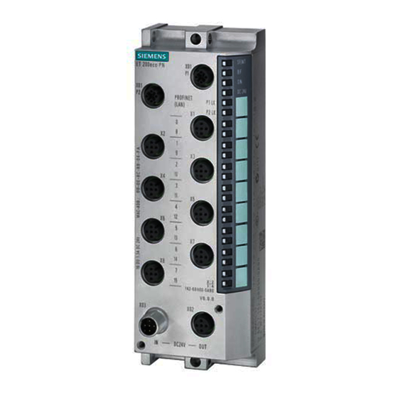
- Page 14 Product overview 1.2 ET 200eco PN Distributed I/O Device Table 1-2 Components of ET 200eco PN (60 mm) Component Function Figure I/O device You connect the sensors and actuators to the I/O device. The I/O device is available in the following variants: • 8 DI DC 24V 8×M12 •...
- Page 15 Product overview 1.2 ET 200eco PN Distributed I/O Device Table 1-3 Components of ET 200eco PN (60 mm) Component Function Figure I/O device You connect the sensors and actuators to the I/O device. The I/O device is available in the following variants: • 4 AO U/I 4×M12 SF/MT LED X03: Voltage infeed...
- Page 16 Product overview 1.2 ET 200eco PN Distributed I/O Device Supports mixed operation of sensors/actuators in the IO-Link, digital input and digital output operating modes on all four ports of the IO-Link Master. Table 1-4 IO-Link Master (6ES7148-6JA00-0AB0) Component Function Figure IO-Link master Connect the following to I/O device: •...
- Page 17 Product overview 1.2 ET 200eco PN Distributed I/O Device Table 1-5 IO-Link Master (6ES7148-6JD00-0AB0) Component Function Figure IO-Link master Connect IO-Link devices or encoders/actu ators to the I/O device. SF/MT LED IO-L1 ... IO-L4: Channel status/channel ① ⑧ fault IO-Link communication BF LED X03: Voltage infeed ②...
- Page 18 Product overview 1.2 ET 200eco PN Distributed I/O Device Further components of ET 200eco PN Component Function Figure Terminal block You can connect up to 10 A per voltage to the terminal block for distribution to the I/O devices. A maximum of 4 A per voltage is available short-circuit protected for each I/O device.
- Page 19 At least STEP 7 V5.4, SP4 is required to configure a ET 200eco PN. The ET 200eco PN can be configured starting from a CPU with extended diagnostics, see FAQ (https://support.automation.siemens.com/WW/view/en/23678970). For information on the individual PROFINET properties that are available for the respective versions of the ET 200eco PN, refer to theFAQ (https://support.automation.siemens.com/WW/view/en/44383954).
-
Page 20: Installing
Installing Two installation variants There are two installation variants: • With mounting rail • Without mounting rail For corresponding conditions, refer to the next chapters. Installation without mounting rail Simple installation The ET 200eco PN distributed I/O device is designed for easy installation. •... - Page 21 Installing 2.1 Installation without mounting rail Procedure 1. Screw the I/O device onto a level surface. Screw the I/O device onto the panel at both mounting fixtures on the top and bottom of the front or side (torque: 3 N/m). Figure 2-1 Mounting the I/O device on a panel (30 mm) ET 200eco PN Operating Instructions, 06/2022, A5E01250250-AN...
- Page 22 Installing 2.1 Installation without mounting rail Figure 2-2 Mounting the I/O device on a panel (60 mm), for example 16 DO DC 24V/1,3A 8×M12 Figure 2-3 Mounting the PD DC 24V 1×7/8" 4×M12 on a panel (45 mm) ET 200eco PN Operating Instructions, 06/2022, A5E01250250-AN...
-
Page 23: Installation With Mounting Rail
Installing 2.3 Mounting position, mounting dimensions Installation with mounting rail Version The mounting rail is available with a length of 500 mm. Installing the mounting rail Cut the 500-mm rail to suit your requirements and drill mounting holes for the M8 screws. You should distribute the mounting holes evenly at a pitch of 182 mm on the rail, starting at a distance of 12 mm from the edge. -
Page 24: Installing The Terminal Block
Installing 2.4 Installing the terminal block Installing the terminal block Properties The terminal block connects the ET 200eco PN and supplies the I/O device with power. The terminal block • can be installed separately, • or be screwed on to each I/O device. Requirements Note that you must wire the terminal block before you install it. -
Page 25: Replacing Labels
Installing 2.5 Replacing labels connector and that it is mounted onto connector X02 of the I/O device. Bolt the terminal block onto the I/O device by tightening the screws. Figure 2-6 Installing the terminal block on an I/O device of 60 mm width See also Wiring the terminal block (Page 56) Terminal block and voltage distributor (Page 221) -
Page 26: Removing Et 200Eco Pn
Installing 2.6 Removing ET 200eco PN Replacing labels 1. Push the screwdriver into the small opening of the label at an angle and then lever it out. Figure 2-7 Removing labels 2. Push the new label into the holder on the device. Removing ET 200eco PN Procedure The ET 200eco PN is wired up and operating. -
Page 27: Wiring
Wiring General rules and regulations for operating an ET 200eco PN Introduction When installing the ET 200eco PN distributed I/O device as part of a plant or system, special rules and regulations need to be adhered to depending on the area of application. This section provides an overview of the most important rules you have to observe when integrating the ET 200eco PN distributed I/O device in a plant or system. -
Page 28: Operating Et 200Eco Pn On Grounded Mains
Wiring 3.2 Operating ET 200eco PN on grounded mains 24 V DC supply The following table identifies requirements you must observe for the 24 V DC supply. With ... You must take into account... Buildings External lightning protection Take lightning protection measures (for example, lightning protection ele 24 V DC supply lines, signal Internal lightning protection ments) - Page 29 Wiring 3.2 Operating ET 200eco PN on grounded mains Definition: Grounded power supply For grounded power supplies the neutral conductor of the supply system is grounded. A short-circuit to ground of a live conductor, or of a grounded part of the system, trips the protective devices.
- Page 30 Wiring 3.2 Operating ET 200eco PN on grounded mains Configuring ET 200eco PN with grounded reference potential In the configuration of the ET 200eco PN with grounded reference potential, any interference currents that occur are discharged to functional ground. The terminals must be connected externally (see the figure "Grounding concept for ET 200eco PN": Connection between 1M and FE).
- Page 31 Wiring 3.2 Operating ET 200eco PN on grounded mains ET 200eco PN in its overall configuration The figure below shows the overall configuration of the ET 200eco PN distributed I/O device (load voltage supply and grounding concept) with supply from a TN-S system. ①...
-
Page 32: Electrical Configuration Of Et 200Eco Pn
Wiring 3.3 Electrical configuration of ET 200eco PN Electrical configuration of ET 200eco PN Electrical isolation The ET 200eco PN electrical configuration features electrical isolation between: • 1L+ Non-switched supply voltage (electronic/sensor/load supply) Electrically isolated from PROFINET IO and 2L+ (load voltage supply) •... -
Page 33: Technical Specifications Of The Cables
Wiring 3.5 Wiring the ET 200eco PN Connection of a digital output to a digital input WARNING When a digital output is connected to a digital output, the respective potential groups have to be observed. Depending on the configuration, 1M and 2M may then be connected, result ing in elimination of the galvanic isolation between 1L+ and 2L+. - Page 34 Wiring 3.5 Wiring the ET 200eco PN What is functional ground? All ET 200eco PN I/O devices have a functional earth connection. This connection is used to suppress interference but not for protective purposes. You establish a direction electrical connection to a point in your plant or a shield using the functional earth connection. EMC interference is discharged directly to earth through this connection.
-
Page 35: Wiring I/O Devices
Wiring 3.5 Wiring the ET 200eco PN Installation To connect ET 200eco PN I/O devices to functional earth with non-conductive base, follow these steps: • Drill 2 fixing holes. • Strip the grounding conductor and crimp on the cable lug. •... - Page 36 Wiring 3.5 Wiring the ET 200eco PN Required accessories • Prefabricated cable with 5-pin M12 cable connector • or 3-, 4- or 5-wire copper cable, flexible and 5‑pin M12 connector (see tables below) • or a Y cable • M12 sealing caps You can find the article numbers in the appendixArticle numbers (Page 227).
- Page 37 Wiring 3.5 Wiring the ET 200eco PN Wiring jacks (DI/DQ) for Y cable To connect digital inputs via a Y cable, you will need: • A Y cable • 2 M12 jacks • A flexible 3-wire or 4-wire copper cable The assignment of Pin 4 depends on which socket of the ET 200eco PN the Y cable is screwed Pin assignment of the sockets for inputs/outputs The pin assignment of the sockets for inputs/outputs can be found in the data for the...
-
Page 38: Pin Assignment Of Connectors
Wiring 3.6 Pin assignment of connectors Pin assignment The pin assignment of the I/O devices is specified in the following chapters. Pin assignment of connectors 3.6.1 Pin assignment of the PROFINET connector PROFINET connector, X01 connector, port 1 and port 2 The tables below list the pin assignment for the PROFINET connectors. -
Page 39: Pin Assignment For Feeding And Looping The Voltage
Wiring 3.6 Pin assignment of connectors 3.6.2 Pin assignment for feeding and looping the voltage Cable connector for supply voltage infeed, X03 connector The table below lists the pin assignment for the supply voltage infeed. Table 3-2 Pin assignment of the M12 cable connector for the supply voltage infeed Assignment View of the cable connector (wiring side) -
Page 40: Pin Assignment Of Digital Inputs
Wiring 3.6 Pin assignment of connectors CAUTION PROFINET IO Modules with PROFINET interfaces may only be operated when all connected nodes are sup plied with SELV/PELV voltages. 3.6.3 Pin assignment of digital inputs I/O device 8 DI DC 24V 4×M12 (6ES7141-6BF00-0AB0) You will find the pin assignment for the 8 DI DC 24V 4×M12 I/O device in the table below. - Page 41 Wiring 3.6 Pin assignment of connectors Assignment of X1 to X8 View of the cable connector (wiring side) Sensor supply ground 1M Input signal DI : Connector X1 Input signal DI : Connector X2 Input signal DI : Connector X3 Input signal DI : Connector X4 Input signal DI...
-
Page 42: Pin Assignment Of Digital Outputs
Wiring 3.6 Pin assignment of connectors 3.6.4 Pin assignment of digital outputs I/O device 8 DO DC 24V/1,3A 4×M12 (6ES7142-6BF00-0AB0) You will find the pin assignment for the 8 DO DC 24V/1,3A 4×M12 I/O device in the table below. Table 3-7 Pin assignment of the M12 cable connector for the 8 DO DC 24V/1,3A 4×M12 I/O device Assignment View of the cable connector (wiring side) Assignment X1 and X2 (1L+ non-switched) - Page 43 Wiring 3.6 Pin assignment of connectors I/O device 8 DO DC 24V/0,5A 4×M12 (6ES7142-6BF50-0AB0) You will find the pin assignment for the 8 DO DC 24V/0,5A 4×M12 I/O device in the table below. Table 3-8 Pin assignment of the M12 cable connector for the 8 DO DC 24V/0,5A 4×M12 I/O device Assignment X1 to X4 (2L+ switched) View of the cable connector (wiring side) Not used Output signal DQ...
- Page 44 Wiring 3.6 Pin assignment of connectors Assignment View of the cable connector (wiring side) Functional earth FE ET 200eco PN Operating Instructions, 06/2022, A5E01250250-AN...
- Page 45 Wiring 3.6 Pin assignment of connectors I/O device 16 DO DC 24V/1,3A 8×M12 (6ES7142-6BH00-0AB0) You will find the pin assignment for the 16 DO DC 24V/1,3A 8×M12 I/O device in the table below. Table 3-10 Pin assignment of the M12 cable connector for the 16 DO DC 24V/1,3A 8×M12 I/O device Assignment View of the cable connector (wiring side) Assignment X1 to X4 (1L+ non-switched)
-
Page 46: Pin Assignment For Parameterizable Digital Input/Digital Output
Wiring 3.6 Pin assignment of connectors When using the Y cable, pin 2 and pin 4 are assigned to pin 4 (B) and pin 4 (A). NOTE The M12 sockets for the supply and I/O have the same coding. Make sure that you wire the supply and the I/O correctly. 3.6.5 Pin assignment for parameterizable digital input/digital output I/O device 8 DIO DC 24V/1,3A 8×M12 (6ES7147-6BG00-0AB0) -
Page 47: Pin Assignment For Io-Link Masters
Wiring 3.6 Pin assignment of connectors 3.6.6 Pin assignment for IO-Link Masters IO-Link Master 4 IO‑L + 8 DI + 4 DO DC 24V/1,3A 8×M12 (6ES7148-6JA00-0AB0) The following tables contain the pin assignments for the IO-Link Master 4 IO‑L + 8 DI + 4 DO DC 24V/1,3A 8×M12. Table 3-12 Pin assignment for IO-Link Master and digital inputs Assignment of X1 to X4 View of the cable connector (wiring side) 24 V sensor supply 1U... - Page 48 Wiring 3.6 Pin assignment of connectors Table 3-14 Pin assignment for digital outputs Assignment X7 and X8 (2L+ switched) View of the cable connector (wiring side) Not used Output signal DQ : Connector X7 Output signal DQ : Connector X8 Supply ground 2M Output signal DQ : Connector X7 Output signal DQ...
-
Page 49: Pin Assignment For Analog Inputs
Wiring 3.6 Pin assignment of connectors A non-interacting connection of devices of various port types (class A and class B) is possible using a 3-wire connecting cable (assignment of pins 1, 3 and 4). NOTICE 24 V encoder supply 1U Only use the 24 V encoder supply 1U supplied by the IO-Link master to supply the devices. - Page 50 Wiring 3.6 Pin assignment of connectors Assignment of X1, X3, X5, X7 View of the cable connector (wiring side) Connector X1: Input signal M Voltage Connector X3: Input signal M Connector X5: Input signal M Connector X7: Input signal M Functional earth FE Current 4-wire transducer...
- Page 51 Wiring 3.6 Pin assignment of connectors Assignment of X2, X4, X6, X8 (for RTD) View of the cable connector (wiring side) 3-conductor Constant current line positive I Measurement cable positive M Measurement cable negative M - and constant current line negative I Functional earth FE 2-conductor Measurement cable positive M...
- Page 52 Wiring 3.6 Pin assignment of connectors Assignment X2, X4, X6, X8 View of the cable connector (for thermocouples and ±80 mV) (wiring side) Connector X2: Input signal M Connector X4: Input signal M Connector X6: Input signal M Connector X8: Input signal M Functional earth FE ①...
- Page 53 Wiring 3.6 Pin assignment of connectors Assignment X1 to X8 (for RTD) View of the cable connector (wiring side) 3-conductor Constant current line positive I Measurement cable positive M Measurement cable negative M - and constant current line negative I Functional earth FE 2-conductor Measurement cable positive M...
-
Page 54: Pin Assignment M12 Compensation Connector For Thermocouples
Wiring 3.6 Pin assignment of connectors 3.6.8 Pin assignment M12 compensation connector for thermocouples M12 compensation connectors (6ES7194-4AB00-0AA0) You will find the pin assignment for the M12 compensation connector in the table below. Assignment X1 View of the M12 compensation connector Measurement cable 1M+ assigned with internal Pt1000 Input signal M... -
Page 55: Pin Assignment For Analog Output
Wiring 3.7 Wiring the terminal block 3.6.9 Pin assignment for analog output I/O device 4 AO U/I 4×M12 (6ES7145-6HD00-0AB0) You will find the pin assignment for the 4 AO U/I 4×M12 I/O device in the table below. Table 3-22 Pin assignment for voltage and current for the 4 AO U/I 4×M12 I/O device Assignment of X1 to X4 View of the cable connector (wiring side) - Page 56 Wiring 3.7 Wiring the terminal block Wiring the connectors Prepare the wires for connection to the terminal block. Figure 3-4 Wiring the terminal block ET 200eco PN Operating Instructions, 06/2022, A5E01250250-AN...
- Page 57 Wiring 3.7 Wiring the terminal block We'll show you an example of the separate installation of the terminal block and how to wire it to several I/O devices. Figure 3-5 Wiring of the terminal block and of several I/O devices You can tap a maximum load of 4 A from each supply voltage of the I/O device. You can loop- through the rest.
- Page 58 Wiring 3.7 Wiring the terminal block Pin assignment The tables below show the pin assignments. Table 3-23 Pin assignment of the insulation displacement terminal block. Assignment View of the insulation displacement ter minal block: 24 V (1L+ non-switched) Ground 1M (non-switched) 24 V (2L+ switched) Ground 2M (switched) Table 3-24 Pin assignment of the M12 connector...
-
Page 59: Wiring The Voltage Distributor
Wiring 3.8 Wiring the voltage distributor Wiring the voltage distributor Wiring the connectors We use an example to show the configuration of the PD DC 24V 1×7/8" 4×M12 voltage distributor with connected I/O devices. Figure 3-7 Wiring the voltage distributor ET 200eco PN Operating Instructions, 06/2022, A5E01250250-AN... - Page 60 Wiring 3.8 Wiring the voltage distributor Pin assignment The tables below show the pin assignments. Assignment of X05 View of the 7/8" cable connector (24 V con nection) Ground 2M (switched) Ground 1M (non-switched) Functional earth FE 24 V (1L+ non-switched) 24 V (2L+ switched) Table 3-26 Pin assignment of the M12 cable connector at the current output Assignment of X01 to X04...
-
Page 61: Looping Profinet And The Supply Voltage
Wiring 3.9 Looping PROFINET and the supply voltage Looping PROFINET and the supply voltage Properties The I/O device is equipped with one connector for the infeed and one socket for loop-through of the supply voltage. The feed connector and the socket for loop-through are interconnected internally. -
Page 62: Configuring
You will need a GSD file, available for download from the Internet (http://support.automation.siemens.com/WW/view/en/19698639/133100). ET 200eco PN family: gsdml-v2.2-siemens-et200eco"date format yyyymmdd".xml Configuring ET 200eco PN on PROFINET IO using STEP 7 1. Start STEP 7 and call up the Options > Install New GSD File menu command in HW Config. -
Page 63: Configuring An Io-Link Master
Configuring 4.2 Configuring an IO-Link master Configuring an IO-Link master 4.2.1 Configuring the IO-Link Master 6ES7148-6JA00-0AB0 Requirements Configuration of the IO-Link Master takes place in two steps: 1. You need STEP 7 as of version V5.4 + SP5 + HSP188 for the IO-Link Master. 2. -
Page 64: Configuring The Io-Link Master 6Es7148-6Jd00-0Ab0
Configuring the IO-Link Master with GSD fileGSD 1. Install the GSD file in HW Config. The GSD file is available on the Internet (https://support.industry.siemens.com/cs/ww/en/view/33291771). 2. Select the IO-Link Master I/O device in the hardware catalog of HW Config. 3. You can freely choose the address space in the Properties > Addresses field for each slot of the IO-Link Master. -
Page 65: Device Names For Et 200Eco Pn
Configuring 4.3 Device names for ET 200eco PN Configuring the submodule of the IO-Link master Requirements • You have configured your automation system. • In the device configuration of the 6ES7148-6JD00-0AB0 IO-Link Master, you have selected the IO-Link port that you want to configure. Procedure 1. - Page 66 Configuring 4.3 Device names for ET 200eco PN You will find detailed information on addressing in PROFINET IO in the the SIMATIC PROFINET system description (http://support.automation.siemens.com/WW/view/en/19292127) System Manual. Requirements • An online PROFINET connection from the programming device to the IO Device is required for assigning the device name to the IO Device.
-
Page 67: Ports Of Et 200Eco Pn
Configuring 4.5 Isochronous real-time communication Ports of ET 200eco PN Introduction The ET 200eco PN can diagnose two ports: X01 P1 R and X01 P2 R: Requirement • The ports must be configured in HW Config. • The port diagnostics must be enabled. Configuring the ports in HW Config In HW Config, configure the two ports in the "Properties of the ET 200eco PN"... -
Page 68: Prioritized Startup
• After station recovery • After activation of IO Devices Detailed information For further information, see the SIMATIC PROFINET system description (http://support.automation.siemens.com/WW/view/en/19292127) System Manual and the Migration from PROFIBUS DP to PROFINET IO (http://support.automation.siemens.com/WW/view/en/19289930) Programming Manual. Device replacement without programming device... -
Page 69: Media Redundancy
Configuring 4.9 Reset to factory settings (PROFINET) Detailed information For further information, see the SIMATIC PROFINET system description (http://support.automation.siemens.com/WW/view/en/19292127) System Manual and the Migration from PROFIBUS DP to PROFINET IO (http://support.automation.siemens.com/WW/view/en/19289930) Programming Manual. Media redundancy Media redundancy Function for ensuring the network and system availability. Redundant transmission links (ring topology) ensures that an alternative communication path is made available if a transmission link fails (starting with STEP 7 V5.5) (not for 6ES7148-6JA00-0AB0 IO-Link Master up to... -
Page 70: Snmp
SNMP tools and are saved to module memory. Following replacement with a brand new module, the R/W objects of the interface module are set to factory settings. See also SIMATIC PROFINET system description (http://support.automation.siemens.com/WW/view/en/19292127) ET 200eco PN Operating Instructions, 06/2022, A5E01250250-AN... -
Page 71: Commissioning
Commissioning Commissioning ET 200eco PN Introduction Your automation system is commissioned depending on the current plant configuration. The section below describes the procedure for commissioning the ET 200eco PN on an IO Controller. Requirements for commissioning the ET 200eco PN on the PROFINET IO Actions Reference ET 200eco PN installed... - Page 72 Commissioning 5.1 Commissioning ET 200eco PN Startup of the ET 200eco PN on the PROFINET IO The schematic diagram below illustrates the startup of the ET 200eco PN on the PROFINET IO: Figure 5-1 Startup of the ET 200eco PN on the PROFINET IO ET 200eco PN Operating Instructions, 06/2022, A5E01250250-AN...
-
Page 73: Maintenance
Maintenance Replacing the fuse Introduction The terminal block is equipped with replaceable fuses. The figure below shows the fuses in the terminal block. Figure 6-1 Fuses in the terminal block Requirements Switch off the supply voltage before you replace any fuses. Result: CPU stop of the ET 200eco PN. -
Page 74: Online Firmware Update By Means Of Step 7 Manager
Maintenance 6.2 Online firmware update by means of STEP 7 Manager Online firmware update by means of STEP 7 Manager Introduction To update the firmware of the ET 200eco PN including its I/O devices, you require the *.UPD files containing the current firmware version. Requirements •... -
Page 75: Acyclic Data Exchange With The Io-Link Library
Reference For an exact description of the procedure, refer to the IO-Link System functional manual on the Internet (https://support.industry.siemens.com/cs/ww/en/view/65949252). The IO-Link block library is available for download on the Internet (https://support.industry.siemens.com/cs/ww/en/view/82981502). You can find additional application examples for IO-Link block library on the Internet (https://support.industry.siemens.com/cs/ww/en/view/90529409). -
Page 76: Exchange Object
Maintenance 6.6 Cleaning the I/O device Exchange object Exchange object With HW Config, the I/O devices are exchanged, for example, an 8-channel I/O device is replaced by a 16-channel I/O device. The following takes place: With the "Exchange object" function, the device name, IP-address, etc. are taken over. The module/channel parameters are set to the "default"... -
Page 77: Interrupt, Error, And System Messages
In the event of an interrupt, interrupt OBs are executed automatically in the CPU of the IO Controller (refer to the System Software for S7-300/400 System and Standard Functions (http://support.automation.siemens.com/WW/view/en/1214574) Manual, chapter "Program design"). Information on the cause and class of the error is already available based on the OB number and start information. - Page 78 • Maintenance required, identified by a yellow wrench icon at the relevant port. See also For additional information, refer to the SIMATIC PROFINET system description (http://support.automation.siemens.com/WW/view/en/19292127) System Manual and the Migration from PROFIBUS DP to PROFINET IO (http://support.automation.siemens.com/WW/view/en/19289930) Programming Manual. ET 200eco PN...
-
Page 79: Diagnostics By Means Of Led Display
Interrupt, error, and system messages 7.3 Diagnostics by means of LED display Diagnostics by means of LED display 7.3.1 Diagnostics using the LED display on the I/O devices LED display The figure below shows the position and arrangement of the LED display on the ET 200eco PN I/O devices: ①... - Page 80 Interrupt, error, and system messages 7.3 Diagnostics by means of LED display Status and error displays SF/MT, BF, ON Table 7-1 Status and error displays of the ET 200eco PN LEDs Meaning Remedy SF/MT IO Device is currently exchanging data with the IO Controller without errors.
-
Page 81: Diagnostics Using Led Display On The Io-Link Masters
Interrupt, error, and system messages 7.3 Diagnostics by means of LED display 7.3.2 Diagnostics using LED display on the IO-Link masters LED display IO-Link Master 4 IO‑L + 8 DI + 4 DO DC 24V/1,3A 8×M12 (6ES7148-6JA00-0AB0) The figure below shows the position and arrangement of the LED display on the IO-Link Master 4 IO‑L + 8 DI + 4 DO DC 24V/1,3A 8×M12. - Page 82 Interrupt, error, and system messages 7.3 Diagnostics by means of LED display Meaning IO-L flashes at 2 Hz • during startup or continuously if no operational IO-Link device as found. LED display IO-Link Master 4 IO‑L 4×M12 (6ES7148-6JD00-0AB0) The figure below shows the position and arrangement of the LED display on the IO-Link Master 4 IO‑L 4×M12.
- Page 83 Interrupt, error, and system messages 7.3 Diagnostics by means of LED display LEDs Q1 to Q4 Valid for an IO-Link port that is in SIO mode. Table 7-4 Status displays of LEDs Q1 to Q4 LEDs Meaning Remedy Q1 to Q4 Input or output value is 1.
-
Page 84: Diagnostics Using The Led Display At The Voltage Distributor
Interrupt, error, and system messages 7.3 Diagnostics by means of LED display 7.3.3 Diagnostics using the LED display at the voltage distributor LED display The figure below shows the position and arrangement of the LED display on the voltage distributor. ①... -
Page 85: Diagnostics Messages Of The I/O Devices
Additional information regarding the data records for PROFINET IO For information on the structure of diagnostics data records, including programming examples, refer to the Migration from PROFIBUS DP to PROFINET IO (http://support.automation.siemens.com/WW/view/en/19289930) Programming Manual. ET 200eco PN Operating Instructions, 06/2022, A5E01250250-AN... -
Page 86: Error Classes For I/O Devices
Interrupt, error, and system messages 7.5 Diagnostics with STEP 7 Structure of the manufacturer-specific diagnostics data records The structure of the diagnostics data records is differentiated based on the BlockVersion. The following block versions apply to the ET 200eco PN: ET 200eco PN Article number BlockVersion 8 DI DC 24V 4×M12 6ES7141-6BF00-0AB0... - Page 87 Interrupt, error, and system messages 7.5 Diagnostics with STEP 7 Error class Error text Meaning Remedy 00110 Wire break • Signal line to a sensor or actuator inter • Correct the process wiring rupted • Replace the sensor or actuator •...
- Page 88 Interrupt, error, and system messages 7.5 Diagnostics with STEP 7 Error class Error text Meaning IO-Link IO-Link Master Device 00111 Overflow • Process variable range exceeded (0x8C10) • Measuring range exceeded (0x8C20) 01000 Underflow Process variable range too small (0x8C30) 01001 Error All the IO-Link error codes not listed here will be mapped to this...
- Page 89 Interrupt, error, and system messages 7.5 Diagnostics with STEP 7 The IO-Link master generates channel diagnostics for each port. The port-specific channel diagnostics are display in the port diagnostics (CET 0x9502 The following table provides an overview of the possible diagnostics events and their meaning.
-
Page 90: Stop Of The Io Controller And Recovery Of The Io Device
See also For more information please refer to the STEP 7 online help and to the programming manual Migration from PROFIBUS DP to PROFINET IO (http://support.automation.siemens.com/WW/view/en/19289930). 7.5.4 STOP of the IO Controller and recovery of the IO Device Diagnostics events triggered after a STOP of the IO Controller Diagnostics frames received from the IO Device while the IO Controller is in STOP do not trigger the start of corresponding OBs after the restart of the IO Controller. -
Page 91: General Technical Data
• EU Directive 2011/65/EU "Restriction of the use of certain hazardous substances in electrical and electronic devices" (RoHS Directive) The EU Declarations of Conformity are available to the relevant authorities at the following address: Siemens AG Digital Industries Factory Automation DI FA TI COS TT P.O. - Page 92 DI FA TI COS TT P.O. Box 1963 D-92209 Amberg The UK declarations of conformity are also available for download from the Siemens Industry Online Support website, under the keyword "Declaration of Conformity". ATEX approval According to EN 60079-15 (Electrical apparatus for potentially explosive atmospheres - Part 15: Type of protection "n"), EN 60079-0 (Electrical apparatus for potentially explosive gas...
- Page 93 General technical data 8.1 Standards and certifications UKEX approval According to EN IEC 60079-7 (Electrical apparatus for potentially explosive atmospheres - Part 7: Increased safety "e"), EN IEC 60079-0 (Electrical apparatus for potentially explosive gas atmospheres - Part 0: General Requirements) and EN 60079-31 (Electrical apparatus for potentially explosive atmospheres –...
- Page 94 General technical data 8.1 Standards and certifications CCCEx approval In accordance with GB/T 3836.3 (Explosive atmospheres - Part 3: Equipment protection by type of protection "e"), GB/T 3836.8 (Explosive atmospheres - Part 8: Equipment protection by type of protection "n") and GB/T 3836.1 (Explosive atmospheres - Part 1: Equipment - General requirements).
- Page 95 General technical data 8.1 Standards and certifications cULus approval Underwriters Laboratories Inc. in accordance with • UL 508 (Industrial Control Equipment) • UL50 Enclosure Type 4X, indoor use only, watertight • CAN/CSA C22.2 No. 142 (Process Control Equipment) NOTE Class 2 power supply unit The components must be supplied with a class 2 power supply unit.
-
Page 96: Emc Compatibility, Shipping And Storage Conditions
• KR (Korean Register of Shipping) • LRS (Lloyds Register of Shipping) • Class NK (Nippon Kaiji Kyokai) The article numbers of the approved I/O devices for the respective classification society can be found here (https://support.industry.siemens.com/cs/ww/en/ps/14244/cert?ct=446). See also PI explosion protection use ecoPN (https://support.industry.siemens.com/cs/ww/en/view/80484830) - Page 97 General technical data 8.2 EMC compatibility, shipping and storage conditions Sinusoidal disturbance variables The table below shows the electromagnetic compatibility of the ET 200eco PN distributed I/O device with respect to sinusoidal disturbances. HF radiation according to IEC 61000-4-3 HF coupling according to Electromagnetic HF field IEC 61000-4-6 Amplitude modulated...
-
Page 98: Mechanical And Climatic Environmental Conditions
General technical data 8.3 Mechanical and climatic environmental conditions Mechanical and climatic environmental conditions Climatic environmental conditions Applicable climatic environmental conditions: Environmental conditions Fields of application Remarks Temperature from 0 °C to 55 °C All mounting positions Temperature change 10 K/h Relative humidity 5 % to max. - Page 99 General technical data 8.3 Mechanical and climatic environmental conditions Designation Article number Fields of application From product version -25 °C to -25 °C to -40 °C to 55 °C 60 °C 60 °C 8 AI RTD/TC 8×M12 6ES7144-6KD50-0AB0 4 AO U/I 4×M12 6ES7145-6HD00-0AB0 4 IO-L + 8 DI + 4 DO DC 24V/1,3A 8×M12 6ES7148-6JA00-0AB0 4 IO-L 4×M12...
- Page 100 General technical data 8.3 Mechanical and climatic environmental conditions Test ... Test standard Terminal and I/O devices Shock Shock, tested in Type of shock: Half-sine accordance with Shock intensity: 30 g peak value, 18 ms duration IEC 60068-2-27 Direction of shock: 3 shocks in each +/- direction at each of the three vertically aligned axes Continuous shock Type of shock: Half-sine...
-
Page 101: Specification Of Dielectric Tests, Protection Class, Degree Of Protection, And Rated
General technical data 8.4 Specification of dielectric tests, protection class, degree of protection, and rated voltage of ET 200eco PN Designation Article number From product version 16 DO DC 24V/1,3A 8×M12 6ES7142-6BH00-0AB0 8 DIO DC 24 V/1,3A 8×M12 6ES7147-6BG00-0AB0 8 AI 4 U/I + 4 RTD/TC 8×M12 6ES7144-6KD00-0AB0 8 AI RTD/TC 8×M12 6ES5144-6KD50-0AB0... -
Page 102: 8.5 Safety-Relevant Symbols For The Et 200Eco Pn Distributed I/O System
General technical data 8.5 Safety-relevant symbols for the ET 200eco PN distributed I/O system Rated voltage for operation The ET 200eco PN distributed I/O device operates at the following rated voltage and corresponding tolerances. Rated voltage Tolerance range DC 24 V 20.4 to 28.8 V DC Safety-relevant symbols for the ET 200eco PN distributed I/O system The following table contains a declaration of the systems than can be located on the modules... -
Page 103: Use Of The Et 200Eco Pn In Zone 2/Zone 22 Hazardous Areas
Approved ET 200eco PN distributed I/O devices You can find the EC type examination certificate with the approved ET 200eco PN I/O devices on the Internet at the following link: Type test (http://support.automation.siemens.com/WW/view/de/71748103) Approval The approval is available in the section Standards and certifications (Page 92). - Page 104 8.6 Use of the ET 200eco PN in zone 2/zone 22 hazardous areas 4. Use the following cables with even connector outlets to wire the different M12 interfaces: – PROFINET: SIEMENS, order number 6XV1 870-8A or 6XV1 871-5T – Supply voltage: SIEMENS, order number 6XV1 801-5D –...
-
Page 105: I/O Device Digital Inputs/Digital Outputs
I/O device digital inputs/digital outputs I/O device digital inputs 9.1.1 I/O device 8 DI DC 24 V 4xM12 Article number 6ES7141-6BF00-0AB0 Properties The 8 DI DC 24V 4×M12 I/O device has the following properties: • 8 digital inputs • Dimensions 30 x 200 mm, dual assignment of the sockets •... - Page 106 I/O device digital inputs/digital outputs 9.1 I/O device digital inputs Block diagram The block diagram below shows the 8 DI DC 24V 4×M12 I/O device. ET 200eco PN Operating Instructions, 06/2022, A5E01250250-AN...
- Page 107 I/O device digital inputs/digital outputs 9.1 I/O device digital inputs Figure 9-1 Block diagram of the 8 DI DC 24V 4×M12 I/O device ET 200eco PN Operating Instructions, 06/2022, A5E01250250-AN...
- Page 108 I/O device digital inputs/digital outputs 9.1 I/O device digital inputs Technical data of the 8 DI DC 24V 4×M12 I/O device Technical data Dimensions and weight Dimensions W x H x D (mm) 30 x 200 x 49 Weight Approx. 550 g Module-specific data Transmission rate 100 Mbps full duplex...
- Page 109 I/O device digital inputs/digital outputs 9.1 I/O device digital inputs Technical data • Ethernet interface 1500 V (IEEE802.3, Type Test) • All other circuit elements 707 V DC (type test) Electrical isolation • Between 1L+ and 2L+ • Between 1L+, channels and all other circuit ele ments •...
-
Page 110: I/O Device 8 Di Dc 24 V 8Xm12
I/O device digital inputs/digital outputs 9.1 I/O device digital inputs Technical data • At "1" to "0" Typ. 3 ms Input characteristic According to IEC 61131, Type 3 Connection of 2-wire proximity switches Supported • Permitted quiescent current Max. 1.5 mA 9.1.2 I/O device 8 DI DC 24 V 8xM12 Article number... - Page 111 I/O device digital inputs/digital outputs 9.1 I/O device digital inputs Block diagram The block diagram below shows the 8 DI DC 24V 8×M12 I/O device. ET 200eco PN Operating Instructions, 06/2022, A5E01250250-AN...
- Page 112 I/O device digital inputs/digital outputs 9.1 I/O device digital inputs Figure 9-2 Block diagram of the 8 DI DC 24V 8×M12 I/O device ET 200eco PN Operating Instructions, 06/2022, A5E01250250-AN...
- Page 113 I/O device digital inputs/digital outputs 9.1 I/O device digital inputs Technical data of the 8 DI DC 24V 8×M12 I/O device Technical data Dimensions and weight Dimensions W x H x D (mm) 60 x 175 x 49 Weight Approx. 910 g Module-specific data Transmission rate 100 Mbps full duplex Transmission mode...
- Page 114 I/O device digital inputs/digital outputs 9.1 I/O device digital inputs Technical data Insulation test voltage • Ethernet interface 1500 V (IEEE802.3, Type Test) • All other circuit elements 707 V DC (type test) Electrical isolation • Between 1L+ and 2L+ • Between 1L+, channels and all other circuit ele ments •...
-
Page 115: I/O Device 16 Di Dc 24 V 8Xm12
I/O device digital inputs/digital outputs 9.1 I/O device digital inputs Technical data • At "0" to "1" Typ. 3 ms • At "1" to "0" Typ. 3 ms Input characteristic According to IEC 61131, Type 3 Connection of 2-wire proximity switches Supported •... - Page 116 I/O device digital inputs/digital outputs 9.1 I/O device digital inputs Block diagram The block diagram below shows the 16 DI DC 24V 8×M12 I/O device. ET 200eco PN Operating Instructions, 06/2022, A5E01250250-AN...
- Page 117 I/O device digital inputs/digital outputs 9.1 I/O device digital inputs Figure 9-3 Block diagram of the 16 DI DC 24V 8×M12 I/O device ET 200eco PN Operating Instructions, 06/2022, A5E01250250-AN...
- Page 118 I/O device digital inputs/digital outputs 9.1 I/O device digital inputs Technical data of the 16 DI DC 24V 8×M12 I/O device Technical data Dimensions and weight Dimensions W x H x D (mm) 60 x 175 x 49 Weight Approx. 910 g Module-specific data Transmission rate 100 Mbps full duplex Transmission mode...
- Page 119 I/O device digital inputs/digital outputs 9.1 I/O device digital inputs Technical data Insulation test voltage • Ethernet interface 1500 V (IEEE802.3, Type Test) • All other circuit elements 707 V DC (type test) Electrical isolation • Between 1L+ and 2L+ • Between 1L+, channels and all other circuit ele ments •...
-
Page 120: Parameter Overview Digital Inputs
I/O device digital inputs/digital outputs 9.1 I/O device digital inputs Technical data • At "0" to "1" Typ. 3 ms • At "1" to "0" Typ. 3 ms Input characteristic According to IEC 61131, Type 3 Connection of 2-wire proximity switches Supported •... -
Page 121: I/O Device Digital Outputs
I/O device digital inputs/digital outputs 9.2 I/O device digital outputs I/O device digital outputs 9.2.1 I/O device 8 DO DC 24 V/1.3A 4xM12 Article number 6ES7142-6BF00-0AB0 Properties The 8 DO DC 24V/1,3A 4×M12 I/O device has the following properties: • 8 digital outputs •... - Page 122 I/O device digital inputs/digital outputs 9.2 I/O device digital outputs Block diagram The block diagram below shows the 8 DO DC 24V/1,3A 4×M12 I/O device. Figure 9-4 Block diagram of the 8 DO DC 24V/1,3A 4×M12 I/O device Technical specifications of the 8 DO DC 24V/1,3A 4×M12 I/O device Technical specifications Dimensions and weight Dimensions W x H x D (mm)
- Page 123 I/O device digital inputs/digital outputs 9.2 I/O device digital outputs Technical specifications Bus protocol PROFINET IO • IRT with the option "high flexibility" • IRT with the option "high performance" Supported Ethernet services PROFINET IO (Device) • ping • • LLDP •...
- Page 124 I/O device digital inputs/digital outputs 9.2 I/O device digital outputs Technical specifications • Between Ethernet and all other circuit elements Yes Status, interrupts, diagnostics Interrupts Diagnostics function • Group error/maintenance Red/yellow "SF/MT" LED • Bus monitoring PROFINET IO Red "BF" LED •...
-
Page 125: I/O Device 8 Do Dc 24 V/0.5A 4Xm12
I/O device digital inputs/digital outputs 9.2 I/O device digital outputs Technical specifications Short-circuit protection of the output Yes, electronic • Response threshold Typ. 1.8 A (per channel) * Make allowances for the maximum total current when configuring the module. 9.2.2 I/O device 8 DO DC 24 V/0.5A 4xM12 Article number 6ES7142-6BF50-0AB0... - Page 126 I/O device digital inputs/digital outputs 9.2 I/O device digital outputs Block diagram The block diagram below shows the 8 DO DC 24V/0,5A 4×M12 I/O device. Figure 9-5 Block diagram of the 8 DO DC 24V/0,5 A 4×M12 I/O device Technical data of the 8 DO DC 24V/0,5A 4×M12 I/O device Technical data Dimensions and weight Dimensions W x H x D (mm)
- Page 127 I/O device digital inputs/digital outputs 9.2 I/O device digital outputs Technical data Supported Ethernet services PROFINET IO (Device) • ping • • LLDP • Network diagnostics (SNMP) • • Prioritized startup • Media redundancy PROFINET interface • Connection socket 2 x M12 •...
- Page 128 I/O device digital inputs/digital outputs 9.2 I/O device digital outputs Technical data Interrupts Diagnostics function • Group error/maintenance Red/yellow "SF/MT" LED • Bus monitoring PROFINET IO Red "BF" LED • Monitoring of supply voltage 1L+ Green "ON" LED • Monitoring of supply voltage 2L+ Green "DC24V"...
-
Page 129: I/O Device 8 Do Dc 24 V/1.3A 8Xm12
I/O device digital inputs/digital outputs 9.2 I/O device digital outputs 9.2.3 I/O device 8 DO DC 24 V/1.3A 8xM12 Article number 6ES7142-6BG00-0AB0 Properties The 8 DO DC 24V/1,3A 8×M12 I/O device has the following properties: • 8 digital outputs • Dimensions 60 x 175 mm, single assignment of the sockets •... - Page 130 I/O device digital inputs/digital outputs 9.2 I/O device digital outputs Block diagram The block diagram below shows the 8 DO DC 24V/1,3A 8×M12 I/O device. Figure 9-6 Block diagram of the 8 DO DC 24V/1,3A 8×M12 I/O device Technical data of the 8 DO DC 24V/1,3A 8×M12 I/O device Technical data Dimensions and weight Dimensions W x H x D (mm)
- Page 131 I/O device digital inputs/digital outputs 9.2 I/O device digital outputs Technical data Bus protocol PROFINET IO • IRT with the option "high flexibility" • IRT with the option "high performance" Supported Ethernet services PROFINET IO (Device) • ping • • LLDP •...
- Page 132 I/O device digital inputs/digital outputs 9.2 I/O device digital outputs Technical data • Between Ethernet and all other circuit elements Yes Status, interrupts, diagnostics Interrupts Diagnostics function • Group error/maintenance Red/yellow "SF/MT" LED • Bus monitoring PROFINET IO Red "BF" LED •...
-
Page 133: I/O Device 8 Do Dc 24V/2.0A 8Xm12
I/O device digital inputs/digital outputs 9.2 I/O device digital outputs Technical data Short-circuit protection of the output Yes, electronic • Response threshold Typ. 1.8 A (per channel) * Make allowances for the maximum total current when configuring the module. 9.2.4 I/O device 8 DO DC 24V/2.0A 8xM12 Article number 6ES7142-6BR00-0AB0... - Page 134 I/O device digital inputs/digital outputs 9.2 I/O device digital outputs Block diagram The block diagram below shows the 8 DO DC 24V/2,0A 8×M12 I/O device. Figure 9-7 Block diagram of the 8 DO DC 24V/2,0A 8×M12 I/O device Technical data of the 8 DO DC 24V/2,0A 8×M12 I/O device Technical data Dimensions and weight Dimensions W x H x D (mm)
- Page 135 I/O device digital inputs/digital outputs 9.2 I/O device digital outputs Technical data Bus protocol PROFINET IO • IRT with the option "high flexibility" • IRT with the option "high performance" Supported Ethernet services PROFINET IO (Device) • ping • • LLDP •...
- Page 136 I/O device digital inputs/digital outputs 9.2 I/O device digital outputs Technical data • Between Ethernet and all other circuit elements Yes Status, interrupts, diagnostics Interrupts Diagnostics function • Group error/maintenance Red/yellow "SF/MT" LED • Bus monitoring PROFINET IO Red "BF" LED •...
-
Page 137: I/O Device 16 Do Dc 24 V/1.3A 8Xm12
I/O device digital inputs/digital outputs 9.2 I/O device digital outputs Technical data Short-circuit protection of the output Yes, electronic • Response threshold Typ. 2.8 A (per channel) * Make allowances for the maximum total current when configuring the module. 9.2.5 I/O device 16 DO DC 24 V/1.3A 8xM12 Article number 6ES7142-6BH00-0AB0... - Page 138 I/O device digital inputs/digital outputs 9.2 I/O device digital outputs Block diagram The block diagram below shows the 16 DO DC 24V/1,3A 8×M12 I/O device. Figure 9-8 Block diagram of the 16 DO DC 24V/1,3A 8×M12 I/O device Technical data of the 16 DO DC 24V/1,3A 8×M12 I/O device Technical data Dimensions and weight Dimensions W x H x D (mm)
- Page 139 I/O device digital inputs/digital outputs 9.2 I/O device digital outputs Technical data Bus protocol PROFINET IO • IRT with the option "high flexibility" • IRT with the option "high performance" Supported Ethernet services PROFINET IO (Device) • ping • • LLDP •...
- Page 140 I/O device digital inputs/digital outputs 9.2 I/O device digital outputs Technical data • Between Ethernet and all other circuit elements Yes Status, interrupts, diagnostics Interrupts Diagnostics function • Group error/maintenance Red/yellow "SF/MT" LED • Bus monitoring PROFINET IO Red "BF" LED •...
-
Page 141: Parameter Overview Digital Outputs
I/O device digital inputs/digital outputs 9.2 I/O device digital outputs Technical data Short-circuit protection of the output Yes, electronic • Response threshold Typ. 1.8 A (per channel) * Make allowances for the maximum total current when configuring the module. 9.2.6 Parameter overview digital outputs Parameters for •... -
Page 142: I/O Device Digital Inputs/Digital Outputs
I/O device digital inputs/digital outputs 9.3 I/O device digital inputs/digital outputs Parameters for 16 DO DC 24V/1,3A 8×M12 (6ES7142-6BH00-0AB0) Parameter Range of values Default setting Range of effectiveness Group diagnostics • Disable Disable Device • Enable Diagnostics: Missing 1L+ or 2L+ •... - Page 143 I/O device digital inputs/digital outputs 9.3 I/O device digital inputs/digital outputs • Digital outputs – Rated load voltage DC 24 V – Output current: 1.3 A per output – Suitable for solenoid valves, DC contactors, and indicator lights – Diagnostics "Missing 1L+ or 2L+" for the I/O device "Wire break at outputs"...
- Page 144 I/O device digital inputs/digital outputs 9.3 I/O device digital inputs/digital outputs Block diagram The block diagram below shows the 8 DIO DC 24V/1,3A 8×M12 I/O device. Figure 9-9 Block diagram of the 8 DIO DC 24V/1,3A 8×M12 I/O device Technical data of the 8 DIO DC 24V/1,3A 8×M12 I/O device Technical data Dimensions and weight Dimensions W x H x D (mm) 60 x 175 x 49 Weight...
- Page 145 I/O device digital inputs/digital outputs 9.3 I/O device digital inputs/digital outputs Technical data Bus protocol PROFINET IO • IRT with the option "high flexibility" • IRT with the option "high performance" Supported Ethernet services PROFINET IO (Device) • ping • • LLDP •...
- Page 146 I/O device digital inputs/digital outputs 9.3 I/O device digital inputs/digital outputs Technical data • Between 1L+, channels and all other circuit ele ments • Between channels • Between Ethernet and all other circuit elements Yes Status, interrupts, diagnostics Interrupts Diagnostics function •...
- Page 147 I/O device digital inputs/digital outputs 9.3 I/O device digital inputs/digital outputs Technical data Input delay • At "0" to "1" Typ. 3 ms • At "1" to "0" Typ. 3 ms Input characteristic According to IEC 61131, Type 3 Connection of 2-wire proximity switches Supported •...
-
Page 148: Parameter Overview Digital Inputs/Digital Outputs
I/O device digital inputs/digital outputs 9.3 I/O device digital inputs/digital outputs 9.3.2 Parameter overview digital inputs/digital outputs Parameters for 8 DIO DC 24V/1,3A 8×M12 (6ES7147-6BG00-0AB0) Parameters Range of values Default setting Range of effectiveness Group diagnostics • Disable Disable Device •... -
Page 149: I/O Device Analog Input/Analog Output
I/O device analog input/analog output 10.1 I/O device analog input 10.1.1 I/O device 8 AI 4 U/I + 4 RTD/TC 8xM12 Article number 6ES7144-6KD00-0AB0 Properties • 4 inputs for voltage and current measurement (2-wire and 4-wire transducers) • 4 inputs for resistance (2-/3-/4-wire transducer), thermal resistor (2-/3-/4-conductor connection system), thermocouple or ±80 mV •... - Page 150 I/O device analog input/analog output 10.1 I/O device analog input • Permitted common-mode voltage AC 10V • Prioritized startup • Media redundancy NOTE During startup As long as no parameters are assigned for the I/O device, the I/O device supplies the pro cess values 0x7FFF.
- Page 151 I/O device analog input/analog output 10.1 I/O device analog input Assignment for RTD View of socket (front view) Socket X2 Socket X4 Socket X6 Socket X8 (Channel 4) (Channel 5) (Channel 6) (Channel 7) Measurement cable Constant current line and measurement cable -, M -, M -, M...
- Page 152 I/O device analog input/analog output 10.1 I/O device analog input Block diagram The block diagram below shows the 8 AI 4 U/I + 4 RTD/TC 8×M12. Figure 10-1 Block diagram 8 AI 4 U/I + 4 RTD/TC 8×M12 Technical specifications Technical specifications Dimensions and weight Dimensions W x H x D (mm) 60 x 175 x 49 Weight Approx.
- Page 153 I/O device analog input/analog output 10.1 I/O device analog input Technical specifications Supported Ethernet services PROFINET IO (Device) • ping • • LLDP • Network diagnostics (SNMP) • • Prioritized startup • Media redundancy PROFINET interface • Connection socket 2 x M12 d-coded •...
- Page 154 I/O device analog input/analog output 10.1 I/O device analog input Technical specifications • Current ±20 mA/17 V for 2-wire transducer, 3.5 V for 4-wire transducer 0 to 20 mA/17 V for 2-wire transducer, 3.5 V for 4-wire transducer 4 to 20 mA/17 V for 2-wire transducer, 3.5 V for 4-wire transducer •...
- Page 155 I/O device analog input/analog output 10.1 I/O device analog input Technical specifications • Resolution for RTD (including overrange) 150 Ω, 300 Ω, 600 Ω, 3000 Ω/15 bps, Ni100, Ni1000, Ni120, Ni200; Ni500, Pt100, Pt1000, Pt200, Pt500/15 bps + sign • Resolution for thermocouples (including over...
- Page 156 I/O device analog input/analog output 10.1 I/O device analog input Technical specifications Interrupts Diagnostics functions • Group error/maintenance Red/yellow "SF/MT" LED • Bus monitoring PROFINET IO Red "BF" LED • Monitoring of supply voltage 1L+ Green "ON" LED • Existing connection to bus Green "P1 LK"...
-
Page 157: Ai Rtd/Tc 8×M12 I/O Device
I/O device analog input/analog output 10.1 I/O device analog input NOTE The accuracy information is valid for static thermal states and changes in ambient temperat ure < 1 K/h. The I/O device achieves the highest accuracy with the 4-wire connection system (see technic al specifications above). - Page 158 I/O device analog input/analog output 10.1 I/O device analog input • Diagnostics – "No 1L+" supply voltage – "Wire break" – "Underflow" – "Overflow" • Permitted common-mode voltage AC 10V • Prioritized startup • Media redundancy NOTE During startup As long as no parameters are assigned for the I/O device, the I/O device supplies the pro cess values 7FFF Pin assignment The tables below show the pin assignment for the 8 AI RTD/TC 8xM12 electronic module.
- Page 159 I/O device analog input/analog output 10.1 I/O device analog input Assignment for RTD View of socket (front view) Socket X1 Socket X2 Socket X3 Socket X4 Socket X5 Socket X6 Socket X7 Socket X8 (Channel (Channel (Channel (Channel (Channel (Channel (Channel (Channel 2-conductor...
- Page 160 I/O device analog input/analog output 10.1 I/O device analog input Block diagram The figure below shows the block diagram of the 8 AI RTD/TC 8xM12 electronic module. ET 200eco PN Operating Instructions, 06/2022, A5E01250250-AN...
- Page 161 I/O device analog input/analog output 10.1 I/O device analog input Figure 10-2 Block diagram 8 AI RTD/TC 8xM12 ET 200eco PN Operating Instructions, 06/2022, A5E01250250-AN...
- Page 162 I/O device analog input/analog output 10.1 I/O device analog input Technical specifications Technical specifications Dimensions and weight Dimensions W x H x D (mm) 60 x 175 x 49 Weight Approx. 930 g Module-specific data Transmission rate 100 Mbps full duplex Transmission mode 100 BASE-TX Autonegotiation Bus protocol...
- Page 163 I/O device analog input/analog output 10.1 I/O device analog input Technical specifications • Voltage ±80 mV • Resistance 150 Ω/10 MΩ 300 Ω/10 MΩ 600 Ω/10 MΩ 3000 Ω/10 MΩ • Thermoresistor Pt100/10 MΩ Pt200/10 MΩ Pt500/10 MΩ Pt1000/10 MΩ Ni100/10 MΩ Ni120/10 MΩ Ni200/10 MΩ Ni500/10 MΩ Ni1000/10 MΩ • Thermocouple Types N, E, J, K Permitted input voltage for voltage input (destruc...
- Page 164 I/O device analog input/analog output 10.1 I/O device analog input Technical specifications Interference suppression, error limits Interference suppression for 46 dB f = n x (f1 ± 0.5%), (f1 = interference frequency) • Common-mode interference (interference 70 dB voltage < 5 V) •...
- Page 165 I/O device analog input/analog output 10.1 I/O device analog input Technical specifications Insulation Insulation test voltage • Ethernet interface 1500 V (IEEE802.3, Type Test) • All other circuit elements 707 V DC (type test) Standards, approvals, certificates Suitable for applications according to AMS 2750 Yes;...
-
Page 166: Parameter Overview Analog Input
I/O device analog input/analog output 10.1 I/O device analog input 10.1.3 Parameter overview analog input Parameters for analog input 8 AI 4 U/I + 4 RTD/TC 8xM12 (6ES7144-6KD00-0AB0) Parameters Range of values Default setting Range of effectiveness Group diagnostics • Disable Disable Device • Enable Diagnostics, missing 1L+ •... - Page 167 I/O device analog input/analog output 10.1 I/O device analog input Parameters Range of values Default setting Range of effectiveness Measuring range, channels 4 to • +/-80 mV Pt100 Standard range Channel • 150 Ω • 300 Ω • 600 Ω •...
- Page 168 I/O device analog input/analog output 10.1 I/O device analog input Parameters for analog input 8 AI RTD/TC 8xM12 (6ES7144-6KD50-0AB0) Parameters Range of values Default setting Range of effectiveness Group diagnostics • Disable Disable Device • Enable Diagnostics, missing 1L+ • Disable Disable Device •...
- Page 169 I/O device analog input/analog output 10.1 I/O device analog input Parameters Range of values Default setting Range of effectiveness • Ni1000 Standard range • TC_EL Typ_N_[NiCrSi_NiSi] • TC_EL Typ_E_[NiCr_CuNi] • TC_EL Typ_J_[Fe_CuNi] • TC_EL Typ_K_[NiCr_Ni] Reference junction for ther • None Internal Channel...
-
Page 170: Parameter Description Analog Input
I/O device analog input/analog output 10.1 I/O device analog input Measurement type Temperature coefficient Measuring range Thermoresistor 4-conductor Ni 0.006180 Ni100 Climatic range / Thermoresistor 3-conductor Ni 0.006720/ Ni100 Standard range / Thermoresistor 2-conductor Ni 0.005 Ni120 Climatic range / Ni120 Standard range / Ni200 Climatic range / Ni200 Standard range / Ni500 Climatic range /... - Page 171 I/O device analog input/analog output 10.1 I/O device analog input frequency suppression "Off (Fast Mode)" means 500 Hz, which corresponds to an integration time of 2 ms for a measurement channel. Temperature unit This parameter is used to select the unit in which the temperature is detected. Reference temperature for TC The reference temperature applies to all channels at which "Fix Ref. Temp."...
- Page 172 I/O device analog input/analog output 10.1 I/O device analog input Smoothing Smoothing of the analog values produces a stable analog signal for further processing. The smoothing of analog values is useful when handling wanted signals (measured values) with a slow rate of change, for example, temperature measurements. The measured values are smoothed by digital filtering.
- Page 173 I/O device analog input/analog output 10.1 I/O device analog input Observe the rules outlined below to handle a wire break in the 1 V to 5 V and 4 mA to 20 mA measuring ranges: Parameters Event Measured Explanation value Enable wire break Wire break 7FFF Diagnostics, wire break Wire break disabled...
- Page 174 I/O device analog input/analog output 10.1 I/O device analog input Reference junction for thermoresistor (TC) A difference in temperature between the measuring point and the free ends of the thermocouple (terminal point) generates a voltage between the free ends, namely the thermoelectric voltage.
-
Page 175: Analog Value Representation For Measuring Ranges With Simatic S7
I/O device analog input/analog output 10.1 I/O device analog input thermocouples. The α value conforms to the standards EN 60751, GOST 6651, JIS C 1604 and ASTM E-1137. The M12 compensation connector is delivered unassembled. You can connect a thermocouple by using terminals 2 and 4 of the M12 compensation connector. The M12 compensation connector is bolted to the round socket X1 on the connection module CM IO 4 x M12 (torque: 1.5 Nm). -
Page 176: Measuring Ranges Of The Analog Input Device In S7 Format
I/O device analog input/analog output 10.1 I/O device analog input Sign The sign (S) of the analog value is always in bit number 15: • "0" → + • "1" → - 10.1.6 Measuring ranges of the analog input device in S7 format Voltage measuring ranges: Measuring range 1 to 5 V Measuring range Units Range... - Page 177 I/O device analog input/analog output 10.1 I/O device analog input Measuring ranges for voltage: ±10 mV Measuring range ±10 V Units Range Decimal Hexadecimal > 11.759 V 32767 7FFF Overflow 11.759 V 32511 7EFF Overrange 27649 6C01 10 V 27648 6C00 Nominal range 7.5 V 20736...
- Page 178 I/O device analog input/analog output 10.1 I/O device analog input Current measuring range: 4 to 20 mA Measuring range Units Range 4 to 20 mA Decimal Hexadecimal > 22.81 mA 32767 7FFF Overflow 22.81 mA 32511 7EFF Overrange 27649 6C01 20 mA 27648 6C00 Nominal range...
- Page 179 I/O device analog input/analog output 10.1 I/O device analog input Measuring range for voltage: ±80 mV Measuring range ±80 mV Units Range Decimal Hexadecimal > 94.1 mV 32767 7FFF Overflow 94.1 mV 32511 7EFF Overrange 27649 6C01 80 mV 27648 6C00 Nominal range 60 mV 20736...
- Page 180 I/O device analog input/analog output 10.1 I/O device analog input Measuring ranges for Pt x00 standard thermal resistor Pt x00 Units Pt x00 Units Pt x00 Units Range Standard Standard Standard Decimal Hexa Decimal Hexa Decimal Hexa in °C in °F in K decimal decimal...
- Page 181 I/O device analog input/analog output 10.1 I/O device analog input Measuring ranges for Ni x00 Standard thermal resistor Ni x00 Units Ni x00 Units Ni x00 Units Range Standard Standard Standard Decimal Hexa Decimal Hexa Decimal Hexa in °C in °F in K decimal decimal...
- Page 182 I/O device analog input/analog output 10.1 I/O device analog input Representation of analog values for thermocouple type E Type E Units Type E Units Type E Units Range in °C in °F in K Decimal Hexa Decimal Hexa Decimal Hexa decimal decimal decimal...
-
Page 183: Dynamic Reference Temperature With Module 8 Ai Rtd/Tc 8Xm12
I/O device analog input/analog output 10.1 I/O device analog input Representation of analog values for thermocouple type K Type K Units Type K Units Type K Units Range in °C in °F in K Decimal Hexa Decimal Hexa Decimal Hexa decimal decimal decimal... - Page 184 I/O device analog input/analog output 10.1 I/O device analog input • All inputs signal overflow (32767) when you start the I/O device 8 AI RTD/TC 8xM12. After receiving a compensation value by means of the data record DS2, the I/O device starts reading the TC inputs and signals correct data. •...
- Page 185 I/O device analog input/analog output 10.1 I/O device analog input Structure of data record DS2 Figure 10-3 Structure of data record DS2 ET 200eco PN Operating Instructions, 06/2022, A5E01250250-AN...
- Page 186 I/O device analog input/analog output 10.1 I/O device analog input Temperature unit Decimal Hexadecimal Standard temperature unit Celsius -1450 to 1550 FA56 to 60E Fahrenheit -2290 to 3110 F70E to C26 Kelvin 1282 to 4282 to 10BA Climatic temperature unit Celsius -14500 to 15500 C75C...
-
Page 187: I/O Device Analog Output
I/O device analog input/analog output 10.2 I/O device analog output Explanation T MW 4 for channel 1 of the 4 AI RTD/TC T MW 6 for channel 2 of the 4 AI RTD/TC T MW 8 for channel 3 of the 4 AI RTD/TC T MW 10 for channel 4 of the 4 AI RTD/TC T MW 12... - Page 188 I/O device analog input/analog output 10.2 I/O device analog output Properties • 4 outputs for voltage or current output • Output ranges: – ±10 V, resolution 15 bits + sign – 1 to 5 V, resolution 15 bits – 0 to 10 V, resolution 15 bits –...
- Page 189 I/O device analog input/analog output 10.2 I/O device analog output Assignment for U/I View of socket (front view) Socket X1 Socket X2 Socket X3 Socket X4 Output signal Functional earth FE Block diagram The block diagram below shows the 4 AO U/I 4×M12. Figure 10-4 Block diagram 4 AO U/I 4xM12 Technical specifications Technical specifications...
- Page 190 I/O device analog input/analog output 10.2 I/O device analog output Technical specifications Weight Approx. 930 g Module-specific data Transmission rate 100 Mbps full duplex Transmission mode 100BASE-TX Autonegotiation Bus protocol PROFINET IO • IRT with the option "high flexibility" • IRT with the option "high performance"...
- Page 191 I/O device analog input/analog output 10.2 I/O device analog output Technical specifications Number of actuator supplies Total current Max. 1 A Short-circuit protection Yes, electronic • Response threshold Min. 1.4 A Actuator selection data Output ranges (Rated value) Voltage ±10 V 1 V to 5 V 0 V to 10 V Current...
- Page 192 I/O device analog input/analog output 10.2 I/O device analog output Technical specifications Operational limit (across the temperature range, Ambient temperature relative to output range) positive negative negative (0 °C to (-25 °C to -25 °C) -40 °C) 0.1% 0.15% 0.3% 0.15% 0.25% 0.4% Basic error limit (operational limit at 25°C, relative 0.08% to output range) 0.1%...
-
Page 193: Parameter Overview Analog Output
I/O device analog input/analog output 10.2 I/O device analog output Technical specifications • Between 1L+, channels and all other circuit ele ments • Between channels • Between Ethernet and all other circuit elements Yes See also Response times for analog input device and output device (Page 259) 10.2.2 Parameter overview analog output Parameters for analog output 4 AO U/I 4xM12 (6ES7145-6HD00-0AB0) -
Page 194: Parameter Description Analog Output
I/O device analog input/analog output 10.2 I/O device analog output Output range Permitted substitute value 1 to 5 V 0.000 V to 5.704 V 0 to 10 V 0.000 V to 11.759 V ±10 V -11.759 V to 11.759 V 0 to 20 mA 0.000 mA to 23.518 mA 4 to 20 mA... -
Page 195: Output Ranges Of Analog Output Device
I/O device analog input/analog output 10.2 I/O device analog output Type of output With this parameter, you set the output type, for example, voltage. For any unused channels, select the disabled setting. For a disabled channel, the conversion time and integration time of the channel = 0 s, and the cycle time is optimized. - Page 196 I/O device analog input/analog output 10.2 I/O device analog output Output range Output range Units Range ±10 V ±20 mA Decimal Hexadecimal 10 V 20 mA 27648 6C00 Nominal range 7.5 V 15 mA 20736 5100 361.7 μV 723.4 nA 0001 0 mA 0000...
-
Page 197: Influence Of The Range Of Values
I/O device analog input/analog output 10.3 Influence of the range of values Output range 0 to Output range 0 to Units Range 10 V 20 mA Decimal Hexadecimal 10 V 20 mA 27648 6C00 Nominal range 7.5 V 15 mA 20736 5100 361.7 μV... - Page 198 I/O device analog input/analog output 10.3 Influence of the range of values The output value lies Result SF LED Diagnostics data range Interrupt of device Before parameter assignment 0 signal Within an incorrect parameter assign Value from the IO Entry Diagnostic interrupt ment Controller...
-
Page 199: Io-Link Master
IO-Link Master 11.1 IO-Link Master (6ES7148-6JA00-0AB0) Article number 6ES7148-6JA00-0AB0 Properties The IO-Link Master 4 IO‑L + 8 DI + 4 DO DC 24V/1,3A 8×M12 has the following technical specifications: • IO-Link Master according to IO-Link specification V1.0 • Dimensions 60 x 175 mm • Double assignment of the sockets • 4 IO-Link ports (Port Class A) •... - Page 200 IO-Link Master 11.1 IO-Link Master (6ES7148-6JA00-0AB0) The module supports the following functions: • Prioritized startup • Media redundancy (as of firmware V7.0) General pin assignment Table 11-1 Pin assignment of sockets X1 to X4 for IO-Link Master and digital inputs Assignment View of socket (front view) Socket X1...
- Page 201 IO-Link Master 11.1 IO-Link Master (6ES7148-6JA00-0AB0) Block diagram The figure below shows the block diagram of the IO-Link Master 4 IO‑L + 8 DI + 4 DO DC 24V/1,3A 8×M12. Figure 11-1 Block diagram of the IO-Link Master 4 IO‑L + 8 DI + 4 DO DC 24V/1,3A 8×M12 Technical data of the IO-Link Master Technical data Dimensions and weight Dimensions W x H x D (mm) 60 x 175 x 49 Weight Approx.
- Page 202 IO-Link Master 11.1 IO-Link Master (6ES7148-6JA00-0AB0) Technical data Transmission mode 100BASE-TX Autonegotiation Bus protocol PROFINET IO • IRT with the option "high flexibility" Supported Ethernet services PROFINET IO (Device) • ping • • LLDP • Network diagnostics (SNMP) • • Prioritized startup •...
- Page 203 IO-Link Master 11.1 IO-Link Master (6ES7148-6JA00-0AB0) Technical data • Between Ethernet and all other circuit elements Yes Status, interrupts, diagnostics Interrupts Diagnostics function • Group error/maintenance Red LED / yellow LED "SF/MT" • Bus monitoring PROFINET IO Red "BF" LED • Monitoring of supply voltage 1L+ Green "ON"...
- Page 204 IO-Link Master 11.1 IO-Link Master (6ES7148-6JA00-0AB0) Technical data Number of inputs that can be controlled simultan 8, in all mounting positions eously Digital outputs Number of outputs IO-Link Device selection data (Port 1 to 4) Cable length, unshielded Max. 20 m Connection of IO-Link devices Port type A Yes;...
-
Page 205: Parameters For Io-Link Master
IO-Link Master 11.1 IO-Link Master (6ES7148-6JA00-0AB0) Technical data Parallel wiring of two outputs • To increase performance • For redundant control of a load Supported Controlling of a digital input Switching frequency • With resistive load Max. 100 Hz • With inductive load Max. - Page 206 IO-Link Master 11.1 IO-Link Master (6ES7148-6JA00-0AB0) Parameters Range of values Default setting Range of effectiveness Channel 5 Diagnostics: Short-circuit of the • Disable Disable Channel group* sensor supply to M • Enable Diagnostics: Wire break • Disable Disable Channel • Enable Channel 6 Diagnostics: Short-circuit of the...
-
Page 207: Functions
IO-Link Master 11.1 IO-Link Master (6ES7148-6JA00-0AB0) 11.1.2 Functions Introduction You can select one of the following operating modes for each of the four ports of the IO-Link Master: • IO-Link • DI • DQ • Disabled You make the selection in the Port Configurator tool during parameterization. If no parameters have been assigned, the ports will be disabled. -
Page 208: Io-Link Master (6Es7148-6Jd00-0Ab0)
IO-Link Master 11.2 IO-Link Master (6ES7148-6JD00-0AB0) Consistency width of 8 byte The IO-Link Master has a consistency width of 8 byte. In addition to the upper limit of 32 byte input and 32 byte output for the entire IO-Link Master, there are other upper limits of 8 byte input and 8 byte output per IO-Link Device (per port). - Page 209 IO-Link Master 11.2 IO-Link Master (6ES7148-6JD00-0AB0) General pin assignment Table 11-5 Pin assignment of sockets X1 to X4 for IO-Link master Assignment View of socket (front view) Socket X1 Socket X2 Socket X3 Socket X4 24 V sensor supply 1U (derived from 1L+ non-switched) 24 V actuator supply 2U (derived from 2L+ switched) Sensor supply ground 1M...
- Page 210 IO-Link Master 11.2 IO-Link Master (6ES7148-6JD00-0AB0) Technical specifications of the IO-Link Master Technical specifications Dimensions and weight Dimensions W x H x D (mm) 30 x 200 x 49 Weight Approx. 550 g Module-specific data Transmission rate 100 Mbps full duplex Transmission mode 100BASE-TX Autonegotiation Bus protocol...
- Page 211 IO-Link Master 11.2 IO-Link Master (6ES7148-6JD00-0AB0) Technical specifications • between 1L+ and 2L+ • between 1L+, channels and all other switching parts • Between channels • between Ethernet and all other switching parts Yes Status, interrupts, diagnostics Interrupts • Hardware interrupt (device notification) Diagnostics function •...
-
Page 212: Configuration
IO-Link Master 11.2 IO-Link Master (6ES7148-6JD00-0AB0) Technical specifications Configuration without S7-PCT supported; autostart function Data for selection of an IO-Link device Cable length, unshielded Max. 20 m Connection of IO-Link devices Port type A Yes; with 3-wire cable Port type B Yes;... -
Page 213: Parameter
IO-Link Master 11.2 IO-Link Master (6ES7148-6JD00-0AB0) When configuring IO-Link submodules, you can select address spaces for I/O data in the following byte scales: • 1 I/1 O + PQI • 2 I + PQI • 2 I/2 O + PQI •... -
Page 214: Explanation Of The Parameters
IO-Link Master 11.2 IO-Link Master (6ES7148-6JD00-0AB0) Parameter Range of values Default setting VendorID* Manufacturer ID of the connected IO-Link device DeviceID* Device ID of the connected IO-Link device Test accuracy / data backup* • Same type (V1.0) without Type compatible (V1.1) with backup &... -
Page 215: Functions
• Type compatible (V1.1) without backup & restore • Type compatible (V1.1) with backup & restore • Type compatible (V1.1) with restore You can find the VendorID and DeviceID on the Internet (https://support.industry.siemens.com/cs/ww/en/view/109748852). See also I/O address space (Page 251) 11.2.4... - Page 216 More information on Master Backup and Master Restore is available in the Master Backup section of the Integration in the Automation System chapter of the IO-Link System (https://support.industry.siemens.com/cs/ww/en/view/65949252) function manual. Identification and maintenance data The identification and maintenance data (I&M data) is information that is saved as read-only (I data) or read/write (M data) on the module.
-
Page 217: Interrupts
IO-Link Master 11.2 IO-Link Master (6ES7148-6JD00-0AB0) Port configuration With a 4 IO-L 4×M12 IO-Link Master as of firmware version V1.1 you can commission the IO- Link submodules (ports) of the IO-Link Masters or the connected IO-Link Devices in two different ways: • Port configuration without S7-PCT •... -
Page 218: Triggering Of A Diagnostic Interrupt
Alarms are made available on the display of the S7-1500 CPU, the CPU Web server and the HMI device. More information on system diagnostics is available in the Diagnostics function manual on the Internet (https://support.industry.siemens.com/cs/ww/en/view/59192926). 11.2.5.1 Triggering of a diagnostic interrupt... -
Page 219: Triggering Of A Pull/Plug Interrupt
IO-Link Master 11.2 IO-Link Master (6ES7148-6JD00-0AB0) Triggering a hardware interrupt In the event of a hardware interrupt the CPU interrupts the processing of the user program and processes the hardware interrupt OB (for example, OB 40). The event that led to the triggering of the interrupt is entered in the start information of the hardware interrupt OB. -
Page 220: Terminal Block And Voltage Distributor
Terminal block and voltage distributor 12.1 Terminal block Article number 6ES7194-6CA00-0AA0 Properties The terminal block has the following properties: • The terminal block can be inserted and screw-mounted on any I/O device • It can also be used separately. • It distributes 10 A per supply voltage 1L+ and 2L+ to the I/O devices. You can tap a maximum load of 4 A from each supply voltage of the I/O device. -
Page 221: Voltage Distributor
Terminal block and voltage distributor 12.2 Voltage distributor Block diagram The block diagram below shows the terminal block. Figure 12-1 Block diagram of the terminal block Technical specifications Dimensions and Weight Dimensions W x H x D (mm) 30 x 50 x 98 Weight Approx. - Page 222 Terminal block and voltage distributor 12.2 Voltage distributor Properties The voltage distributor PD DC 24V 1×7/8" 4×M12 has the following properties: • It distributes the centrally fed supply voltage (7/8") to 4 connectors (M12). • Integrated electronic short-circuit protection • Direct connection of up to 4 I/O devices •...
- Page 223 Terminal block and voltage distributor 12.2 Voltage distributor Block diagram The figure below shows the block diagram of the voltage distributor PD DC 24V 1×7/8" 4×M12. Figure 12-2 Block diagram of the voltage distributor PD DC 24V 1×7/8" 4×M12 Technical specifications Dimensions and Weight Dimensions W x H x D (mm) 45 x 175 x 49 Weight Approx.
- Page 224 Terminal block and voltage distributor 12.2 Voltage distributor Dimensions and Weight • All mounting positions to 45 °C for X1 and X2 in total max. 4 A for 1L+ for X1 and X2 in total max. 4 A for 2L+ for X3 and X4 in total max.
-
Page 225: Signal Names
Signal names Signal names Signal names of the I/O devices Signal name Meaning Input external auxiliary voltage DC (x: load group) Ground external auxiliary voltage DC (x: load group) Digital input (x: load group) Digital output (x: load group) Digital input/digital output (x: load group) Sensor supply voltage, channel n 24 V sensor supply 1U (derived from 1L+ non-switched) -
Page 226: Article Numbers
Article numbers I/O devices Table B-1 I/O devices: Article numbers Designation Article number Digital input devices 8 DI DC 24V 4×M12 6ES7141-6BF00-0AB0 8 DI DC 24V 8×M12 6ES7141-6BG00-0AB0 16 DI DC 24V 8×M12 6ES7141-6BH00-0AB0 Digital output devices 8 DO DC 24V/1,3A 4×M12 6ES7142-6BF00-0AB0 8 DO DC 24V/0,5A 4×M12 6ES7142-6BF50-0AB0... - Page 227 Article numbers Designation Article number M12 cover caps 3RX9802-0AA00 10 items/package, 10 items M12 cover caps AS-Interface 3RK1901-1KA00 10 items/package, 10 items Labels 3RT1900-1SB10 10 x 7 mm, pale turquoise, 816 items per pack Accessories for the interface "PROFINET M12 connector X1 P1 R or X1 P2 R LAN" Raw cables and connectors PROFINET M12 connector 1 item per...
- Page 228 Article numbers Designation Article number PROFINET M12 connecting cable 0.3 m 6XV1870-8GE30 Trailable cable 0.5 m 6XV1870-8GE50 • Preassembled with M12 connectors, angled, 1.0 m 6XV1870-8GH10 fixed lengths, 1 unit 1.5 m 6XV1870-8GH15 2.0 m 6XV1870-8GH20 3.0 m 6XV1870-8GH30 5.0 m 6XV1870-8GH50 10.0 m 6XV1870-8GN10...
- Page 229 Article numbers Designation Article number M12 compensation connector for thermocouples 6ES7194-4AB00-0AA0 Accessories for the interface "DC 24 V IN/OUT M12 (X02/X03)" Raw cables and connectors IE Power M12 Cable Connector PRO, plug-in connector for connection to 6GK1907-0DB10-6AA3 PS791-1PRO power supply for 24 V DC supply voltage with mounting instructions, 4-pin, A-coded, 3 units IE Power M12 Cable Connector Pro, connection socket for connecting 6GK1907-0DC10-6AA3...
- Page 230 Article numbers Accessories for voltage distributors Designation Article number Accessories for the interface "DC 24V IN 7/8" (X05)" Raw cables and connectors 7/8" connector with axial cable exit for field assembly ET 200, socket 6KG1905-0FB00 insert 7/8" connector (screw mechanism), angled, socket insert, 5 items/package 3RK1902-3DA00 Energy Cable 6XV1830-8AH10 Trailable power cable, 5 x 1.5 mm...
- Page 231 Article numbers Designation Article number 7/8" connecting cable for power supply of the ET 200, pre 3.0 m 6XV1822-5BH30 assembled cable with 7/8" connectors 180° at both sides 5.0 m 6XV1822-5BH50 (one side female connector, one side male connector), 10.0 m 6XV1822-5BN10 5-pole 15.0 m...
- Page 232 Article numbers Technical Product Data - CD ROM Designation Contents Article number Technical Product Data for Contains the following technical 6ES7991-0CC00-0YX0 CAx Applications product data for CAD/CAE systems: • Technical specifications accord ing to ECAD component stand ard V1.2 • Graphical data (drawings) •...
-
Page 233: Dimensional Drawings
Dimensional drawings ET 200eco PN Operating Instructions, 06/2022, A5E01250250-AN... -
Page 234: Dimensional Drawings
Dimensional drawings C.1 Dimensional drawings Dimensional drawings ET 200eco PN Operating Instructions, 06/2022, A5E01250250-AN... - Page 235 Dimensional drawings C.1 Dimensional drawings Dimensional drawing of the I/O devices of 30 mm width ET 200eco PN Operating Instructions, 06/2022, A5E01250250-AN...
- Page 236 Dimensional drawings C.1 Dimensional drawings The figure shows the dimensional drawing of the I/O devices: ET 200eco PN Operating Instructions, 06/2022, A5E01250250-AN...
- Page 237 Dimensional drawings C.1 Dimensional drawings • 8 DI DC 24V 4×M12 ET 200eco PN Operating Instructions, 06/2022, A5E01250250-AN...
- Page 238 Dimensional drawings C.1 Dimensional drawings • 8 DO DC 24V/1,3A 4×M12 ET 200eco PN Operating Instructions, 06/2022, A5E01250250-AN...
- Page 239 Dimensional drawings C.1 Dimensional drawings • 8 DO DC 24V/0,5A 4×M12 ET 200eco PN Operating Instructions, 06/2022, A5E01250250-AN...
- Page 240 Dimensional drawings C.1 Dimensional drawings • 4 IO‑L 4×M12 ET 200eco PN Operating Instructions, 06/2022, A5E01250250-AN...
- Page 241 Dimensional drawings C.1 Dimensional drawings Dimensional drawing of the I/O devices of 60 mm width The figure shows the dimensional drawing of the I/O devices: • 8 DI DC 24V 8×M12 (current figure) • 16 DI DC 24V 8×M12 • 8 DO DC 24V/1,3A 8×M12 •...
- Page 242 Dimensional drawings C.1 Dimensional drawings Dimensional drawing of the I/O devices of 60 mm width (with 4 I/O connectors) The figure shows the dimensional drawing of the I/O devices: • 4 AO U/I 4×M12 ET 200eco PN Operating Instructions, 06/2022, A5E01250250-AN...
- Page 243 Dimensional drawings C.1 Dimensional drawings Dimensional drawing of the voltage distributor The figure shows the dimensional drawing of the voltage distributor PD DC 24V 1×7/8" 4×M12 ET 200eco PN Operating Instructions, 06/2022, A5E01250250-AN...
- Page 244 Dimensional drawings C.1 Dimensional drawings Dimensional drawing of the terminal block The figure shows the dimensional drawing of the terminal block: • Separately • Installed on an I/O device ET 200eco PN Operating Instructions, 06/2022, A5E01250250-AN...
- Page 245 Dimensional drawings C.1 Dimensional drawings Dimensional drawing of the mounting rail The figure shows the dimensional drawing of the mounting rail: • Separately • with an I/O device of 30 mm width • with an I/O device of 60 mm width ET 200eco PN Operating Instructions, 06/2022, A5E01250250-AN...
-
Page 246: Connection Examples
Connection examples Connection of resistance thermometers to the analog inputs Connection example 8 AI RTD/TC 8xM12 The figure below shows connection examples for 2-, 3- and 4-conductor connections. 2-conductor 3-conductor 4-conductor Figure D-1 Connection examples: 2-, 3- and 4-conductor Connection of thermocouples to the analog inputs Introduction Different options are available for the analog I/O device 8 AI RTD/TC 8xM12 for compensation of the reference junction temperature. - Page 247 Connection examples D.2 Connection of thermocouples to the analog inputs below. In practice, different connection variants may be possible due to the conditions on site. Connection example "No" compensation as reference junction ① Copper cables ② e. g. compensating box (per channel); thermocouple type B does not need a compensating box ③...
- Page 248 Connection examples D.2 Connection of thermocouples to the analog inputs Connection example "RTD (0)" as reference junction • With M12 compensation connector (integrated resistance thermometer Pt1000) ① Direct connection of the thermocouple or with compensating lines ② M12 compensation connector (terminals 1 and 3 assigned with internal Pt1000) only on round socket X1.
- Page 249 Connection examples D.2 Connection of thermocouples to the analog inputs Connection example "Dynamic reference temperature" as reference junction ① Copper cables ② Thermocouple at 8 AI RTD/TC 8xM12 ③ e. g. Pt100 in the area of the reference junction ④ RTD module of another station Figure D-6 Connection example "Dynamic reference temperature"...
-
Page 250: I/O Address Space
I/O address space I/O device 8 DI DC 24V 4×M12 Assignment in the process image inputs per device: Figure E-1 Address space of 8 DI DC 24V 4×M12 I/O device I/O device 8 DI DC 24V 8×M12 Assignment in the process image inputs per device: Figure E-2 Address space of 8DI DC 24V 8×M12 I/O device ET 200eco PN Operating Instructions, 06/2022, A5E01250250-AN... - Page 251 I/O address space I/O device 16 DI DC 24V 8×M12 Assignment in the process image inputs per device: Figure E-3 Address space of 16 DI DC 24V 8×M12 I/O device I/O device 8 DO DC 24V/1,3A 4×M12 Assignment in the process image output per device: Figure E-4 Address space of 8 DO DC 24V/1,3A 4×M12 I/O device ET 200eco PN Operating Instructions, 06/2022, A5E01250250-AN...
- Page 252 I/O address space I/O device 8 DO DC 24V/0,5A 4×M12 Assignment in the process image output per device: Figure E-5 Address space of 8 DO DC 24V/0,5A 4×M12 I/O device I/O device 8 DO DC 24V/1,3A 8×M12 and 8 DO DC 24V/2,0A 8×M12 Assignment in the process image output per device: Figure E-6 Address space of I/O device 8 DO DC 24V/1,3A 8×M12 and 8 DO DC 24V/2,0A 8×M12 ET 200eco PN Operating Instructions, 06/2022, A5E01250250-AN...
- Page 253 I/O address space I/O device 16 DO DC 24V/1,3A 8×M12 Assignment in the process image output per device: Figure E-7 Address space of 16 DO DC 24V/1,3A 8×M12 I/O device I/O device 8 DIO DC 24V/1,3A 8×M12 Assignment in the process image inputs per device: Figure E-8 Address space of 8 DIO DC 24V/1,3A 8×M12 I/O device ET 200eco PN Operating Instructions, 06/2022, A5E01250250-AN...
- Page 254 I/O address space I/O device 8 AI 4 U/I + 4 RTD/TC 8×M12 Assignment in the process image inputs per device: Figure E-9 Address space of 8 AI 4 U/I + 4 RTD/TC 8×M12 I/O device I/O device 8 AI RTD/TC 8×M12 Assignment in the process image inputs per device: Figure E-10 Address space of 8 AI RTD/TC 8×M12 I/O device ET 200eco PN Operating Instructions, 06/2022, A5E01250250-AN...
- Page 255 I/O address space I/O device 4 AO U/I 4×M12 Assignment in the process image output per device: Figure E-11 Address space of 4 AO U/I 4×M12 I/O device IO-Link Master 4 IO-L + 8 DI + 4 DO DC 24V/1,3A 8×M12 During the STEP 7 configuration, you can select the address space according to use.
- Page 256 I/O address space Slot "8 DI + 4DO" has its own address space. The scope amounts to one byte inputs and one byte outputs. Figure Figure E-13 Address space of the inputs and outputs of the IO-Link Master 4 IO‑L + 8 DI + 4 DO DC 24V/1,3A 8×M12 IO-Link Master 4 IO-L 4×M12 During the configuration, you can select the address space according to use.
- Page 257 I/O address space The following figure shows the assignment of the address spaces of a submodule/port with the IO-Link Master 4 IO-L 4×M12, if you have configured the port in IO-Link mode. Figure E-16 Address space of the inputs and outputs and of the PQI byte of the IO-Link Master 4 IO‑L 4×M12 in IO-Link mode ET 200eco PN Operating Instructions, 06/2022, A5E01250250-AN...
-
Page 258: Response Times For Analog Input Device And Output Device
Response times for analog input device and output device Response times for analog input device Conversion time The basic conversion time depends directly on the conversion method of the analog input channel (integrating method, instantaneous value conversion). For the integrating conversion method, the integration time is included directly in the conversion time. -
Page 259: Response Times For Analog Output Device
Response times for analog input device and output device F.2 Response times for analog output device Response times for analog output device Conversion time The conversion time of the analog output channels includes the transfer of digitized output values from internal memory, and their digital-to-analog conversion. Cycle time The analog output channels are converted for the device with an execution time plus the sequential conversion time for channels 0, 1, 2, and 3. - Page 260 Response times for analog input device and output device F.2 Response times for analog output device This figure shows the response time of an analog output channel: Response time Cycle time, corresponding to the processing time of the device and the conversion time of the channel Settling time New digital output value applied...
-
Page 261: Fail-Safe Shutdown Of Et 200Eco Pn Standard Modules
Fail-safe shutdown of ET 200eco PN standard modules Back-up oriented shutdown of ET 200eco PN standard modules Introduction The following structure describes how to perform a fail-safe shutdown of ET 200eco PN standard modules. In the configuration shown in the diagram below (e.g. with the safety shutdown device 3SK1), all digital outputs that are connected to the 2L+ and 2M supply (24 V switched) of the ET 200eco PN standard modules are switched to the safe OFF state. - Page 262 Fail-safe shutdown of ET 200eco PN standard modules G.1 Back-up oriented shutdown of ET 200eco PN standard modules Block diagram Figure G-1 Higher-level safety shutdown of the outputs WARNING When you use a pp-switching safety shutdown device, the power supply cable for connec tion of the ET 200eco PN modules must be routed cross-circuit proof.
- Page 263 In this FAQ, you will find the SIMATIC standard modules that are suitable for safety-related shutdown. Request German Technical Inspectorate report (Report no. SN95432T) You can request copies of the German Technical Inspectorate report at the following address: SIEMENS AG Digital Industries DI FA SEA SYS DE AMB Postfach 1963...
-
Page 264: Open Source Software
License Conditions and Disclaimers for Open Source Software and other Licensed Software In the product "ET 200eco PN IO-Link Master 4xM12 - V1.0", Copyright Siemens AG, 2016 (hereinafter "Product"), the following Open Source Software is used either unchanged or in a... - Page 265 Open Source Software ET 200eco PN Operating Instructions, 06/2022, A5E01250250-AN...
-
Page 266: Glossary
Glossary Automation system Programmable logic controller for the open-loop and closed-loop control of process sequences of the process engineering industry and manufacturing technology. The automation system consists of different components and integrated system functions depending on the automation task. Autonegotiation Configuration protocol in the Fast Ethernet. - Page 267 Glossary Device name Because a fixed IP address is assigned to the device name, an IO Device must have a device name in order to be addressed by an IO Controller. With PROFINET, this procedure is used because names are easier to handle than complex IP addresses. The assignment of a device name for a specific IO Device can be compared with the setting of the PROFIBUS address for a DP slave.
- Page 268 Glossary External lightning protection External plant components at which galvanic coupling of lightning surges can occur. Corresponds with lightning protection zone 0 and 0 Fast Ethernet Fast Ethernet describes the standard for transferring data with 100 Mbps. This transfer technology used the 100 Base-T standard for this. Firmware update Updating the firmware of modules, for example, after functional enhancements to the latest firmware version (update).
- Page 269 Glossary IO-Link IO-Link is a point-to-point connection to conventional and intelligent sensors/actuators via unshielded standard cable in proven 3-conductor technology. IO-Link is backwards compatible with all DI/DQ sensors/actuators. Circuit state channel and data channel designed in 24 VDC technology. Isochronous real-time communication Synchronized transmission method for the cyclic exchange of IRT data between PROFINET devices A reserved bandwidth is available within the send cycle for IRT IO data.
- Page 270 Glossary Process image (I/O) The CPU transfers the values from the input and output modules to this memory area. At the beginning of the cyclic program, the signal states of the input modules are transferred to the process input image. At the end of the cyclic program the process image of the outputs is transferred as a signal state to the output modules.
- Page 271 Glossary PROFINET device model A PROFINET device can have a modular and compact structure. A modular PROFINET device consists of slots into which the modules are inserted. The modules have channels which are used to read and output process signals. A compact device has the same design. However, it cannot be physically expanded, this means that no modules/submodules can be inserted.
- Page 272 Glossary In the office area and in automation technology, devices support a wide range of manufacturers on the Ethernet SNMP. SNMP-based applications can be operated parallel to applications with PROFINET on the same network. The scope of the supported functions varies depending on the device type. A switch, for example, has more functions than a CP 1616.
-
Page 273: Index
Index 16 DI DC 24V 8×M12 8 AI 4 U/I + 4 RTD/TC 8×M12 Properties, 116 Properties, 150 Pin assignment, 116 Pin assignment, 151 Block diagram, 117 Block diagram, 153 Technical data, 119 Technical specifications, 153 Parameters, 121 8 AI 4 U/I + 4 RTD/TC 8xM12 16 DO DC 24V/1,3A 8×M12 Parameter, 167 Parameters, 143... - Page 274 Index 8 DO DC 24V/1,3A 8×M12 Parameters, 142 Basic conversion time, 259 8 DO DC 24V/1.3A 4×M12 Basic knowledge, 4 Properties, 122 Pin assignment, 122 Burst pulses, 97 Block diagram, 123 Technical specifications, 123 8 DO DC 24V/1.3A 8×M12 Properties, 130 Climatic environmental conditions, 99 Pin assignment, 130 Commissioning...
- Page 275 Index Electrical isolation HW Config, 63, 68 between..., 33 Electromagnetic compatibility, 97 Electrostatic discharge, 97 I/O device EMC, 97 Wiring, 36 EMERGENCY-STOP devices, 28 Identification and maintenance data, 217 Emission of radio interference, 98 IEC 204, 28 Error types I/O devices, 87 Installing, 21 ET 200eco PN Insulation test, 102...
- Page 276 Index PELV Grounded extra-low-voltage, 30 M12 connector Pin assignment connection, 37 PROFINET connector, 39 Maintenance interrupts , 79 For supply voltage infeed, 40 Manual For loop-through of the supply voltage , 40 Purpose, 4 8 DI DC 24V 4×M12, 41 Measuring range 8 DI DC 24V 8xM12, 41 16 DI DC 24V 8xM12, 42...
- Page 277 Index Replacing the fuse Terminal block, 74 Technical data Representation of analog values, 181, 181, 182, I/O device 8 DI DC 24V 4×M12, 109 I/O device 8 DI DC 24V 8×M12, 114 Reset to factory settings (PROFINET), 70 I/O device 16 DI DC 24V 8×M12, 119 I/O device 8 DO DC 24V/0,5A 4×M12, 127 Response time, 260 I/O device 8 DO DC 24V/1,3A 8×M12, 131...
- Page 278 Index Y cable, 37 ET 200eco PN Operating Instructions, 06/2022, A5E01250250-AN...