Siemens SIMATIC ET 200eco PN M12-L Equipment Manual
I/o device digital outputs dq 8x24vdc/2a m12-l 8xm12
Hide thumbs
Also See for SIMATIC ET 200eco PN M12-L:
- Operating instructions manual (278 pages) ,
- Compact operating instructions (156 pages) ,
- System manual (127 pages)
Table of Contents
Advertisement
Quick Links
Advertisement
Table of Contents

Related Manuals for Siemens SIMATIC ET 200eco PN M12-L


Summary of Contents for Siemens SIMATIC ET 200eco PN M12-L
- Page 2 I/O device digital outputs DQ 8x24VDC/2A M12-L 8xM12 (6ES7142-6BR00-0BB0) Preface ET 200eco PN M12-L Documentation Guide SIMATIC Product overview Wiring ET 200eco PN I/O device digital outputs PROFINET IO DQ 8x24VDC/2A M12-L 8xM12 (6ES7142-6BR00-0BB0) EtherNet/IP Equipment Manual Modbus TCP Technical specifications Dimension drawing 02/2022 A5E46575328-AC...
- Page 3 Note the following: WARNING Siemens products may only be used for the applications described in the catalog and in the relevant technical documentation. If products and components from other manufacturers are used, these must be recommended or approved by Siemens. Proper transport, storage, installation, assembly, commissioning, operation and maintenance are required to ensure that the products operate safely and without any problems.
-
Page 4: Preface
Preface Purpose of the documentation This equipment manual supplements the ET 200eco PN M12-L Distributed I/O System (https://support.industry.siemens.com/cs/ww/en/view/109778292) system manual. Functions that relate in general to the distributed I/O devices ET 200eco PN M12-L are described in this system manual. - Page 5 Siemens' products and solutions undergo continuous development to make them more secure. Siemens strongly recommends that product updates are applied as soon as they are available and that the latest product versions are used. Use of product versions that are no longer supported, and failure to apply the latest updates may increase customers' exposure to cyber threats.
-
Page 6: Table Of Contents
Table of contents Preface ..............................3 ET 200eco PN M12-L Documentation Guide ..................7 Product overview ..........................11 Properties .......................... 11 Operator controls and display elements ................14 Wiring ..............................15 Terminal and block diagram ....................15 Pin assignment ........................16 PROFINET IO ............................ - Page 7 Table of contents Dimension drawing ..........................58 Dimension drawing......................58 I/O device digital outputs DQ 8x24VDC/2A M12-L 8xM12 (6ES7142-6BR00-0BB0) Equipment Manual, 02/2022, A5E46575328-AC...
-
Page 8: Et 200Eco Pn M12-L Documentation Guide
This arrangement enables you to access the specific content you require. Basic information The system manual describes in detail the configuration, installation, wiring and commissioning of the SIMATIC ET 200eco PN M12-L distributed I/O system. The STEP 7 online help supports you in the configuration and programming. Device information... - Page 9 You must register once to use the full functionality of "mySupport". You can find "mySupport" on the Internet (https://support.industry.siemens.com/My/ww/en). Application examples The application examples support you with various tools and examples for solving your automation tasks.
- Page 10 You can find the SIMATIC Automation Tool on the Internet (https://support.industry.siemens.com/cs/ww/en/view/98161300). PRONETA SIEMENS PRONETA (PROFINET network analysis) allows you to analyze the plant network during commissioning. PRONETA features two core functions: • The topology overview automatically scans the PROFINET and all connected components.
- Page 11 ET 200eco PN M12-L Documentation Guide SINETPLAN SINETPLAN, the Siemens Network Planner, supports you in planning automation systems and networks based on PROFINET. The tool facilitates professional and predictive dimensioning of your PROFINET installation as early as in the planning stage. In addition, SINETPLAN supports you during network optimization and helps you to exploit network resources optimally and to plan reserves.
-
Page 12: Product Overview
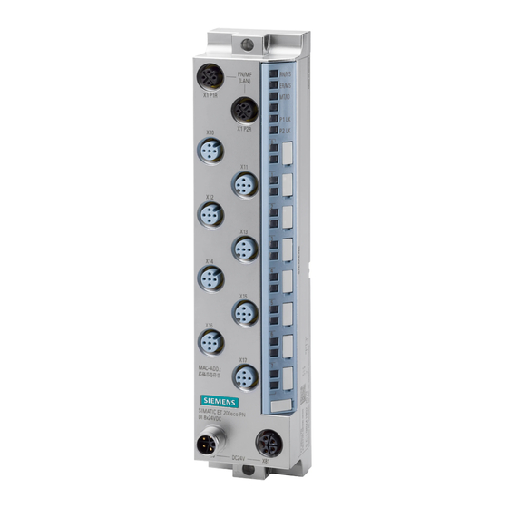
Product overview Properties Article number 6ES7142-6BR00-0BB0 View of the I/O device Figure 2-1 View of the I/O device DQ 8x24VDC/2A M12-L 8xM12 I/O device digital outputs DQ 8x24VDC/2A M12-L 8xM12 (6ES7142-6BR00-0BB0) Equipment Manual, 02/2022, A5E46575328-AC... - Page 13 Product overview 2.1 Properties Properties The I/O device has the following technical properties: • Using the MultiFieldbus function, it connects the ET 200eco PN M12-L distributed I/O system with one of the following bus protocols: – PROFINET IO – EtherNet/IP –...
- Page 14 • Connectors and cables • M12 sealing cap See also You can find additional information on the accessories in the ET 200eco PN M12-L distributed I/O system (https://support.industry.siemens.com/cs/ww/en/view/109778292) system manual. I/O device digital outputs DQ 8x24VDC/2A M12-L 8xM12 (6ES7142-6BR00-0BB0) Equipment Manual, 02/2022, A5E46575328-AC...
-
Page 15: Operator Controls And Display Elements
Product overview 2.2 Operator controls and display elements Operator controls and display elements The figure below shows the operator controls and display elements of the DQ 8x24VDC/2A M12-L 8xM12 I/O device. ① PN/MF (LAN): Sockets for connecting MultiFieldbus ② RN/NS: RUN/network status LED ③... -
Page 16: Wiring
Wiring Terminal and block diagram The figure below shows an example of the pin assignment of signal outputs with single and dual assignment of the sockets. I/O device digital outputs DQ 8x24VDC/2A M12-L 8xM12 (6ES7142-6BR00-0BB0) Equipment Manual, 02/2022, A5E46575328-AC... -
Page 17: Pin Assignment
Wiring 3.2 Pin assignment ① Bus interface with integrated 2-port switch Supply voltage 1L+ (non-switched) ② Monitoring Ground 1M (non-switched) ③ DQ circuit Load voltage 2L+ (switched) ④ Internal supply voltage Ground 2M (switched) ⑤ Output (dual assignment of the socket) Ground with reverse polarity protection, divert- ed from 2M (switched) ⑥... - Page 18 Wiring 3.2 Pin assignment Pin assignment of sockets for digital outputs The table below shows the pin assignment of the 8 sockets for the connection of the digital outputs. Table 3- 2 Pin assignment for digital outputs Assignment Front view of the sockets X10 to X17 - sockets for digital outputs X10, X12, X11, X13,...
- Page 19 Wiring 3.2 Pin assignment The following graphic shows the assignment of the output signals to the respective sockets with dual or single assignment. Figure 3-2 Assignment of output signals with dual or single assignment of sockets Pin assignment of the connector for infeed of the supply voltage (M12 L-coded) The table below shows the pin assignment of the M12 L-coded connector for infeed of the supply voltage.
- Page 20 Wiring 3.2 Pin assignment Pin assignment of the socket for loop-through of the supply voltage (M12 L-coded) The table below shows the pin assignment of the M12 L-coded socket for loop-through of the supply voltage. Table 3- 4 Pin assignment of the supply voltage socket Assignment of the Assignment Front view of the...
-
Page 21: Profinet Io
PROFINET IO Parameters/address space 4.1.1 Parameters The table below shows the parameters for the I/O device DQ 8x24VDC/2A M12-L 8xM12. Table 4- 1 Configurable parameters and their defaults (GSD file) Parameters Value range Default Scope with configuration software, e.g. STEP 7 (TIA Portal) Diagnostics: Undervoltage 1L+ Disable... -
Page 22: Address Space
PROFINET IO 4.1 Parameters/address space Diagnostics: Short-circuit Enabling of the diagnostics for short-circuit of the output to ground. Diagnostics: Wire break Enabling of diagnostics when the line between the actuator and the I/O device is interrupted. Reaction to CPU STOP With this parameter, you set the reaction of the digital outputs of the I/O device after a CPU STOP: •... - Page 23 PROFINET IO 4.1 Parameters/address space Address space for configuration as 1 x 8-channel DQ 8x24VDC The following figure shows the address space allocation for the configuration as 8-channel I/O device digital outputs without value status. Figure 4-1 Address space for configuration as 1 x 8-channel DQ 8x24VDC without value status Value status (Quality Information, QI) The value status is always returned with the following configuration options: •...
- Page 24 PROFINET IO 4.1 Parameters/address space Address space for configuration as 1 x 8-channel DQ 8x24VDC MSO With the configuration 1 x 8-channel I/O device (module-internal shared output, MSO), the channels 0 to 7 (incl. value status) of the I/O device are copied into two submodules. Channels 0 to 7 are then available with identical values in various submodules.
- Page 25 You can find information on the functionality Module-internal Shared Input/Shared Output (MSI/MSO) in the STEP 7 online help or in the function manual SIMATIC PROFINET with STEP 7 (https://support.industry.siemens.com/cs/ww/en/view/49948856). I/O device digital outputs DQ 8x24VDC/2A M12-L 8xM12 (6ES7142-6BR00-0BB0) Equipment Manual, 02/2022, A5E46575328-AC...
-
Page 26: Interrupts/Diagnostics Alarms
PROFINET IO 4.2 Interrupts/diagnostics alarms Interrupts/diagnostics alarms 4.2.1 Status and error displays LED displays The figure below shows the LED displays (status and error displays) of the I/O device DQ 8x24VDC/2A M12-L 8xM12. ① RN/NS: RUN/network status LED ② ER/MS: ERROR/module status LED ③... - Page 27 PROFINET IO 4.2 Interrupts/diagnostics alarms Meaning of the LEDs The following tables set out the meaning of the status and error displays. Measures for dealing with diagnostics alarms can be found in the section Diagnostics alarms (Page 28). Behavior of the LEDs RN/NS (RUN/network status), ER/MS (ERROR/module status) and MT/IO (MAINT/IO status) on PROFINET Table 4- 3 Fault display of the LEDs...
- Page 28 PROFINET IO 4.2 Interrupts/diagnostics alarms PWR LED Table 4- 4 Status display of the PWR LED PWR LED Meaning Load voltage 2L+ is missing or too low Load voltage 2L+ present P1 LK and P2 LK LEDs Table 4- 5 Error display of the P1 LK and P2 LK LEDs LEDs Meaning...
-
Page 29: Interrupts
PROFINET IO 4.2 Interrupts/diagnostics alarms 4.2.2 Interrupts The I/O device digital outputs DQ 8x24VDC/2A M12-L 8xM12 supports diagnostic interrupts and maintenance alarms. Diagnostic interrupt The I/O device generates a diagnostic interrupt on the following events: • Wire break • Internal module fault •... -
Page 30: Maintenance Events
PROFINET IO 4.2 Interrupts/diagnostics alarms Table 4- 7 Diagnostics alarms, their meanings and corrective measures Diagnostics alarm Error code Meaning Corrective measures Wire break Fault in the external circuitry Check the external circuitry and correct the fault. Actuator faulty Replace the actuator. Actuator circuit impedance too high Use a different actuator type or modify the wiring. -
Page 31: Ethernet/Ip
EtherNet/IP Functions/parameters/address space 5.1.1 Supported EtherNet/IP functions Supported functions The table below shows the functions that the module supports with EtherNet/IP. Supported functions Remarks I/O communication with scanner FW 5.1.x or higher Parameter assignment FW 5.1.x or higher Reading diagnostics FW 5.1.x or higher Normative CIP objects FW 5.1.x or higher... -
Page 32: Parameters
EtherNet/IP 5.1 Functions/parameters/address space Supported CIP objects for EtherNet/IP The table below shows the functions that the module supports with EtherNet/IP. Supported CIP object Remarks Identity object FW 5.1.x or higher Assembly object FW 5.1.x or higher Connection Manager object FW 5.1.x or higher TCP/IP Interface object FW 5.1.x or higher... -
Page 33: Explanation Of The Parameters
EtherNet/IP 5.1 Functions/parameters/address space 5.1.3 Explanation of the parameters Diagnostics: Undervoltage 1L+ Enabling of the diagnostics for insufficient supply voltage 1L+. Diagnostics: Missing 2L+ Enabling of the diagnostics for missing or insufficient load voltage 2L+. Diagnostics: Short-circuit Enabling of the diagnostics for short-circuit of the output to ground. Diagnostics: Wire break Enabling of diagnostics when the line between the actuator and the I/O device is interrupted. - Page 34 EtherNet/IP 5.1 Functions/parameters/address space Configuration options of the DQ 8x24VDC/2A M12-L 8xM12 I/O device When the I/O device is configured using a GSD file, the configurations are available under different short designations/device names in the device view of MFCT. The following configurations are possible: Table 5- 2 Configuration options Configuration...
- Page 35 EtherNet/IP 5.1 Functions/parameters/address space Address space for configuration as 1 x 8-channel DQ 8x24VDC QI The following figure shows the address space allocation for the configuration as 8-channel I/O device digital outputs with value status. The addresses of the channels are derived from the start address.
- Page 36 EtherNet/IP 5.1 Functions/parameters/address space The following figure shows the assignment of the address space with submodules 1 and 2 and the value status. Figure 5-3 Address space for configuration as 1 x 8-channel DQ 8x24VDC MSO with value status I/O device digital outputs DQ 8x24VDC/2A M12-L 8xM12 (6ES7142-6BR00-0BB0) Equipment Manual, 02/2022, A5E46575328-AC...
- Page 37 Address space for configuration as 2 x 4-channel DQ 8x24VDC S Reference You can find information about the Module Internal Shared Input/Shared Output (MSI/MSO) functionality in the MultiFieldbus (https://support.industry.siemens.com/cs/ww/en/view/109773209) Function Manual SIMATIC PROFINET with STEP 7 (https://support.industry.siemens.com/cs/ww/en/view/49948856). I/O device digital outputs DQ 8x24VDC/2A M12-L 8xM12 (6ES7142-6BR00-0BB0) Equipment Manual, 02/2022, A5E46575328-AC...
-
Page 38: Diagnostics
EtherNet/IP 5.2 Diagnostics Diagnostics 5.2.1 Status and error displays for EtherNet/IP LED displays The figure below shows the LED displays (status and fault displays) of the I/O device DQ 8x24VDC/2A M12-L 8xM12. ① RN/NS: RUN/network status LED ② ER/MS: ERROR/module status LED ③... - Page 39 EtherNet/IP 5.2 Diagnostics Behavior of the LEDs RN/NS (RUN/network status), ER/MS (ERROR/module status) and MT/IO (MAINT/IO status) on EtherNet/IP The LEDs display the status with the highest priority if there are different LED states due to overlaid events. (0 = off, 1 = green flashing, 2 = green, 3 = yellow, 4 = red flashing, 5 = red) The following table shows the meaning of the RN/NS, ER/MS LEDs and MT/IO LEDs for EtherNet/IP: Table 5- 3...
- Page 40 EtherNet/IP 5.2 Diagnostics LEDs Meaning Remedy Hardware or firmware defective. You can read out the ser- vice data with MFCT. Flashes Flashes Flashes The "Node flash test" is running (the P1 LK and P2 LK LEDs are also flashing). Flashes Flashes Flashes PWR LED...
- Page 41 EtherNet/IP 5.2 Diagnostics Channel status/channel fault LED Table 5- 6 Status and fault display of the channel status/channel fault LED LEDs Meaning Channel sta- tus/channel fault Process value = 0 Process value = 1 Channel diagnostics I/O device digital outputs DQ 8x24VDC/2A M12-L 8xM12 (6ES7142-6BR00-0BB0) Equipment Manual, 02/2022, A5E46575328-AC...
-
Page 42: Modbus Tcp
Modbus TCP Functions/parameters/address space 6.1.1 Supported Modbus TCP functions Supported functions The table below shows the functions that the module supports with Modbus TCP. Supported functions RegLayoutVer- Remarks sion I/O communication with Modbus client V1.0 FW 5.1.x or higher Free user registers (e.g. for coordination of the redundancy) V1.0 FW 5.1.x or higher Device information... -
Page 43: Parameters
Modbus TCP 6.1 Functions/parameters/address space 6.1.2 Parameters The table below shows the parameters for the I/O device DQ 8x24VDC/2A M12-L 8xM12. Table 6- 1 Configurable parameters and their defaults (GSD file) Parameters Value range Default Effective range with configura- tion software, for example, MFCT Diagnostics: Undervoltage 1L+ Disable Channel... -
Page 44: Update Time Of The I/O Data
Modbus TCP 6.1 Functions/parameters/address space Reaction to CPU STOP With this parameter, you set the reaction of the digital outputs of the I/O device after a CPU STOP: • Shutdown: The digital output is de-energized. • Keep last value: The last value of the digital output remains activated. •... - Page 45 Modbus TCP 6.1 Functions/parameters/address space Address space for configuration as 1 x 8-channel DQ 8x24VDC The following figure shows the address space allocation for the configuration as 8-channel I/O device digital outputs without value status. Figure 6-1 Address space for configuration as 1 x 8-channel DQ 8x24VDC without value status Value status (Quality Information, QI) The value status is always returned with the following configuration options: •...
- Page 46 Modbus TCP 6.1 Functions/parameters/address space Address space for configuration as 1 x 8-channel DQ 8x24VDC QI The following figure shows the address space allocation for the configuration as 8-channel I/O device digital outputs with value status. The addresses of the channels are derived from the start address.
- Page 47 Modbus TCP 6.1 Functions/parameters/address space The following figure shows the assignment of the address space with submodules 1 and 2 and the value status. Figure 6-3 Address space for configuration as 1 x 8-channel DQ 8x24VDC MSO with value status I/O device digital outputs DQ 8x24VDC/2A M12-L 8xM12 (6ES7142-6BR00-0BB0) Equipment Manual, 02/2022, A5E46575328-AC...
- Page 48 Address space for configuration as 2 x 4-channel DQ 8x24VDC S Reference You can find information about the Module Internal Shared Input/Shared Output (MSI/MSO) functionality in the MultiFieldbus (https://support.industry.siemens.com/cs/ww/en/view/109773209) Function Manual SIMATIC PROFINET with STEP 7 (https://support.industry.siemens.com/cs/ww/en/view/49948856). I/O device digital outputs DQ 8x24VDC/2A M12-L 8xM12 (6ES7142-6BR00-0BB0) Equipment Manual, 02/2022, A5E46575328-AC...
-
Page 49: Diagnostics
Modbus TCP 6.2 Diagnostics Diagnostics 6.2.1 Status and error displays for Modbus TCP LED displays The figure below shows the LED displays (status and fault displays) of the I/O device DQ 8x24VDC/2A M12-L 8xM12. ① RN/NS: RUN/network status LED ② ER/MS: ERROR/module status LED ③... - Page 50 Modbus TCP 6.2 Diagnostics Behavior of the LEDs RN/NS (RUN/network status), ER/MS (ERROR/module status) and MT/IO (MAINT/IO status) on modbus TCP The LEDs display the status with the highest priority if there are different LED states due to overlaid events. (0 = off, 1 = green flashing, 2 = green, 3 = yellow, 4 = red flashing, 5 = red) The following table shows the meaning of the RN/NS, ER/MS LEDs and MT/IO LEDs for Modbus TCP: Table 6- 3...
- Page 51 Modbus TCP 6.2 Diagnostics PWR LED Table 6- 4 Status display of the PWR LED PWR LED Meaning Load voltage 2L+ is missing or too low Load voltage 2L+ present P1 LK and P2 LK LEDs Table 6- 5 Error display of the P1 LK and P2 LK LEDs LEDs Meaning Remedy...
-
Page 52: Technical Specifications
Technical specifications of the I/O device DQ 8x24VDC/2A M12-L 8xM12 The following table shows the technical specifications as of the issue date. You can find a data sheet including daily updated technical specifications on the Internet (https://support.industry.siemens.com/cs/de/en/pv/6ES7142-6BR00-0BB0/td?dl=en). Article number 6ES7142-6BR00-0BB0... - Page 53 Technical specifications Article number 6ES7142-6BR00-0BB0 Load voltage 2L+ 24 V • Rated value (DC) 20.4 V • permissible range, lower limit (DC) 28.8 V • permissible range, upper limit (DC) Yes; against destruction • Reverse polarity protection Input current Current consumption (rated value) 65 mA;...
- Page 54 Technical specifications Article number 6ES7142-6BR00-0BB0 Output delay with resistive load 50 µs; at rated load • "0" to "1", max. 100 µs; at rated load • "1" to "0", max. Parallel switching of two outputs • for uprating • for redundant control of a load Switching frequency 100 Hz •...
- Page 55 Technical specifications Article number 6ES7142-6BR00-0BB0 PROFINET IO Device Services – Yes; 250 µs to 4 ms in 125 µs frame – Prioritized startup – Shared device – Number of IO Controllers with shared de- vice, max. Redundancy mode • PROFINET system redundancy (S2) –...
- Page 56 Technical specifications Article number 6ES7142-6BR00-0BB0 Modbus TCP Services – read coils (code=1) – read discrete inputs (code=2) – Read Holding Registers (Code=3) – write single coil (code=5) – write multiple coils (code=15) – Write Multiple Registers (Code=16) – Parameter change by master –...
- Page 57 Technical specifications Article number 6ES7142-6BR00-0BB0 Diagnostics indication LED Yes; green LED • RUN LED Yes; red LED • ERROR LED Yes; Yellow LED • MAINT LED Yes; green/red LED • NS LED Yes; green/red LED • MS LED Yes; red-green-yellow LED •...
- Page 58 Technical specifications Article number 6ES7142-6BR00-0BB0 connection method / header Design of electrical connection 4/5-pin M12 circular connectors Design of electrical connection for the inputs and M12, 5-pin, A-coded outputs Design of electrical connection for supply voltage M12, 4-pin, L-coded Dimensions Width 45 mm Height...
- Page 59 Dimension drawing Dimension drawing The figure below shows the dimension drawing of the I/O device digital outputs DQ 8x24VDC/2A M12-L 8xM12 in front and side views. Figure A-1 Dimension drawing I/O device digital outputs DQ 8x24VDC/2A M12-L 8xM12 (6ES7142-6BR00-0BB0) Equipment Manual, 02/2022, A5E46575328-AC...