ABB TTF300 Manual
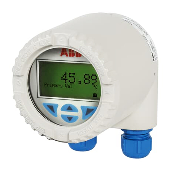
Field-mount temperature transmitter
Hide thumbs
Also See for TTF300:
- Commissioning instructions (364 pages) ,
- Operating instruction (92 pages) ,
- Safety instructions (24 pages)
Table of Contents
Advertisement
Quick Links
—
A BB MEA SU RE ME NT & A NA L YT I C S | C O MMI SSI ON I N G I NS T RU C TI O N | C I / TT F 3 0 0 - E N R EV . H
TTF300
Field-mount temperature transmitter
—
Introduction
TTF300
The TTF300 is available with the HART,
PROFIBUS PA and FOUNDATION Fieldbus
communication protocols.
The TTF300 has global approvals for explosion
protection up to Zone 0.
The TTF300 implements various NAMUR
recommendations, including NE 89 and NE 107.
Safety-relevant applications up to SIL 3
(redundant) are supported in accordance with
IEC 61508.
Temperature transmitter for all
communications protocols.
Redundancy thanks to two inputs.
Measurement made easy
Additional Information
Additional documentation on TTF300 is available for
download free of charge at
www.abb.com/temperature.
Alternatively simply scan this code:
Advertisement
Table of Contents

Related Manuals for ABB TTF300


Summary of Contents for ABB TTF300
- Page 1 Redundancy thanks to two inputs. Measurement made easy — Introduction Additional Information TTF300 The TTF300 is available with the HART, Additional documentation on TTF300 is available for PROFIBUS PA and FOUNDATION Fieldbus download free of charge at communication protocols. www.abb.com/temperature.
-
Page 2: Table Of Contents
TTF300 FIELD-MOUNT TEMPERATURE TRANSMITTER | CI/TTF300-EN REV. H Table of contents Product identification ........... 22 Safety ................4 Name plate ................22 General information and instructions ....... 4 Explosion protection marking for devices with one Warnings ................4 type of protection ............22 Intended use ................. - Page 3 TTF300 FIELD-MOUNT TEMPERATURE TRANSMITTER | CI/TTF300-EN REV. H Commissioning ............39 General ................39 Checks prior to commissioning........39 Communication..............39 HART® Communication ..........39 PROFIBUS® Communication......... 40 FOUNDATION Fieldbus® Communication ....41 Basic Setup ................41 Operation ..............42 Safety instructions ............
-
Page 4: Safety
TTF300 FIELD-MOUNT TEMPERATURE TRANSMITTER | CI/TTF300-EN REV. H 1 Safety Warnings General information and instructions The warnings in these instructions are structured as follows: These instructions are an important part of the product and must be retained for future reference. -
Page 5: Intended Use
• When using as a SIL-device in safety-relevant applications, ABB and its affiliates are not liable for damages and/or losses the corresponding SIL-Safety Manual should be observed. related to such security breaches, any unauthorized access,... -
Page 6: Use In Potentially Explosive Atmospheres In Accordance With Atex And Iecex
A list of standards, including the output data to which the device conforms, can be found in the examination certificate or manufacturer’s declaration supplied with the device. • In devices with several types of protection, for example TTF300 -E4, observe the ‘Product Identification’ chapter in the operating or commissioning instruction before commissioning. Transmitter... -
Page 7: Lcd Indicator
TTF300 FIELD-MOUNT TEMPERATURE TRANSMITTER | CI/TTF300-EN REV. H ATEX flameproof (enclosure) | intrinsic safety IECEx flameproof (enclosure) Permitted for zone 1 and 2 (flameproof enclosure) | Zone 0, 1 and Approved for use in Zone 1 and 2. 2 (intrinsic safety). -
Page 8: Temperature Data
TTF300 FIELD-MOUNT TEMPERATURE TRANSMITTER | CI/TTF300-EN REV. H … 2 Use in potentially explosive atmospheres in accordance with ATEX and IECEx Temperature data Electrical data Transmitter Transmitter ATEX / IECEx intrinsic safety, ATEX increased safety as well Intrinsic safety type of protection Ex ia IIC (Part 1) -
Page 9: Lcd Indicator
In this case, the electric data of the transmitter for the intrinsic safety type of protection Ex ia IIC (Part 1) for TTF300-E1H and TTF300-H1H, Ex ia IIC (Part 2) as well Ex ia IIC (Part 3) should be complied with. -
Page 10: Installation Instructions
TTF300 FIELD-MOUNT TEMPERATURE TRANSMITTER | CI/TTF300-EN REV. H … 2 Use in potentially explosive atmospheres in accordance with ATEX and IECEx Installation instructions ATEX / IECEx / EAC-Ex The installation, commissioning, maintenance and repair of Installation instructions for cable glands... -
Page 11: Electrical Connections
TTF300 FIELD-MOUNT TEMPERATURE TRANSMITTER | CI/TTF300-EN REV. H Maintenance Intrinsic safety installation check Check the cable glands during each maintenance session. If the If transmitters are operated in an intrinsically safe circuit, proof cable is slack, retighten the cap(s) of the cable glands. - Page 12 Risk of explosion! When using the device in areas which require the ‘Ga’ equipment protection level - EPL (Zone 0), the TTF300 types should be installed with aluminum housings to protect against mechanical impact loads or friction.
- Page 13 TTF300 FIELD-MOUNT TEMPERATURE TRANSMITTER | CI/TTF300-EN REV. H ATEX – Zone 1 (20) ATEX – Zone 2 and Zone 22 Marking: II 2 G (1D) Ex [ia IIIC Da] ib IIC T6...T1 Gb Marking: II 3 G Ex nA IIC T6...T1 Gc...
- Page 14 TTF300 FIELD-MOUNT TEMPERATURE TRANSMITTER | CI/TTF300-EN REV. H … 2 Use in potentially explosive atmospheres in accordance with ATEX and IECEx … Installation instructions In addition, the following points must be observed for TTF300 Dust explosion protection – Zone 21 HART (TTF300-E5H) from HW rev. 02.00.00:...
- Page 15 TTF300 FIELD-MOUNT TEMPERATURE TRANSMITTER | CI/TTF300-EN REV. H Dust explosion protection – Zone 0/21 Flameproof (enclosure) – Zone 1 Housing design: ATEX II 2D Ex tb IIIC T135°C Db Housing design: ATEX II 2G Ex db IIC T6/T4 Gb Transmitter design: ATEX II 1G Ex ia IIC T6...T1 Ga...
-
Page 16: Commissioning
TTF300 FIELD-MOUNT TEMPERATURE TRANSMITTER | CI/TTF300-EN REV. H … 2 Use in potentially explosive atmospheres in accordance with ATEX and IECEx … Installation instructions Commissioning The transmitter must be connected using suitable cable and The commissioning and parameterization of the device may also... -
Page 17: Operating Instructions
• A waiting time of at least four minutes should be observed • The device may only be repaired by the ABB Service before opening the device. Department. • Repairs on flameproof joints are not permitted. -
Page 18: Use In Potentially Explosive Atmospheres In Accordance With Fm And Csa
TTF300 FIELD-MOUNT TEMPERATURE TRANSMITTER | CI/TTF300-EN REV. H 3 Use in potentially explosive atmospheres in accordance with FM and CSA Note • Further information on the approval of devices for use in potentially explosive atmospheres can be found in the explosion protection test certificates (at www.abb.com/temperature). -
Page 19: Lcd Indicator
TTF300 FIELD-MOUNT TEMPERATURE TRANSMITTER | CI/TTF300-EN REV. H LCD indicator CSA Explosion Proof and Intrinsically Safe FM Intrinsically Safe Model TTF300-R7H (R1H + R3H) Control Drawing SAP_214 748 To HW rev. 01.07: I.S. Class I Div 1 and Div 2, Group: A, B, C, D or... -
Page 20: Installation Instructions
TTF300 FIELD-MOUNT TEMPERATURE TRANSMITTER | CI/TTF300-EN REV. H … 3 Use in potentially explosive atmospheres in accordance with FM and CSA Installation instructions FM / CSA Proof of intrinsic safety is said to have been provided if the The installation, commissioning, maintenance and repair of... -
Page 21: Commissioning
Alternatively, an Ex modem can be connected to the circuit • The device may only be repaired by the ABB Service outside the potentially explosive atmosphere. Department. •... -
Page 22: Product Identification
TTF300 FIELD-MOUNT TEMPERATURE TRANSMITTER | CI/TTF300-EN REV. H 4 Product identification Name plate Note The name plates displayed are examples. The device identification plates affixed to the device can differ from this representation. Note The ambient temperature range specified on the name plate Figure 13: PROFIBUS PA®... -
Page 23: Explosion Protection Marking For Devices With Several
TTF300 FIELD-MOUNT TEMPERATURE TRANSMITTER | CI/TTF300-EN REV. H Explosion protection marking for devices with several types of protection Coding of the type of protection of the device in accordance Devices with several types of protection may only be operated in with ordering information can also refer to different explosion one of the possible types of protection. -
Page 24: Transport And Storage
Transporting the device purposes: All devices delivered to ABB must be free from any hazardous Observe the following instructions: materials (acids, alkalis, solvents, etc.). •... -
Page 25: Installation
TTF300 FIELD-MOUNT TEMPERATURE TRANSMITTER | CI/TTF300-EN REV. H 6 Installation Mounting Note When using the device in potentially explosive atmospheres, note the additional data in Use in potentially explosive atmospheres in accordance with ATEX and IECEx on page 6 and... -
Page 26: Opening And Closing The Housing
TTF300 FIELD-MOUNT TEMPERATURE TRANSMITTER | CI/TTF300-EN REV. H … 6 Installation Rotating the LCD indicator Opening and closing the housing DANGER Danger of explosion if the device is operated with the transmitter housing or terminal box open! While using the device in potentially explosive atmospheres... -
Page 27: Electrical Connections
TTF300 FIELD-MOUNT TEMPERATURE TRANSMITTER | CI/TTF300-EN REV. H 7 Electrical connections Protection of the transmitter from damage Safety instructions caused by highly energetic electrical DANGER interferences Improper installation and commissioning of the device The transmitter has no switch-off elements. Therefore, carries a risk of explosion. -
Page 28: Suitable Protective Measures
TTF300 FIELD-MOUNT TEMPERATURE TRANSMITTER | CI/TTF300-EN REV. H … 7 Electrical connections … Protection of the transmitter from Cable glands damage caused by highly energetic The cable diameter must be appropriate for the cable gland used electrical interferences so that IP rating IP 66 /IP 67 or NEMA 4X can be maintained. This must be checked during installation. -
Page 29: Shielding Of The Sensor Connecting Cable
TTF300 FIELD-MOUNT TEMPERATURE TRANSMITTER | CI/TTF300-EN REV. H Shielding of the sensor connecting cable To ensure the system benefits from optimum electromagnetic interference immunity, the individual system components, and the connection cables in particular, need to be shielded. The shield must be connected to the ground reference plane. -
Page 30: Additional Examples For Shielding / Grounding
TTF300 FIELD-MOUNT TEMPERATURE TRANSMITTER | CI/TTF300-EN REV. H … 7 Electrical connections … Shielding of the sensor connecting cable Additional examples for shielding / grounding Insulated sensor measuring inset (thermocouple, mV, RTD, Ohm), transmitter housing grounded The shielding of the sensor connection cable is grounded via the grounded transmitter housing. This shielding is insulated from the sensor. - Page 31 TTF300 FIELD-MOUNT TEMPERATURE TRANSMITTER | CI/TTF300-EN REV. H Insulated sensor measuring inset (thermocouple, mV, RTD, Ohm), transmitter housing not grounded The shielding of the power supply cable and the shielding of the sensor connection cable are connected to one another via the transmitter housing.
-
Page 32: Terminal Assignment
TTF300 FIELD-MOUNT TEMPERATURE TRANSMITTER | CI/TTF300-EN REV. H … 7 Electrical connections Terminal assignment Resistance thermometers (RTD) / resistors (potentiometer) A Potentiometer, four-wire circuit I Sensor 1 B Potentiometer, three-wire circuit J Sensor 2* C Potentiometer, two-wire circuit K 4 to 20 mA HART®, PROFIBUS PA®, FOUNDATION Fieldbus®... -
Page 33: Thermocouples / Voltages And Resistance
TTF300 FIELD-MOUNT TEMPERATURE TRANSMITTER | CI/TTF300-EN REV. H Thermocouples / voltages and resistance thermometers (RTD) / thermocouple combinations A 2 x voltage measurement* H Sensor 1 B 1 x voltage measurement I Sensor 2* C 2 x thermocouple* J 4 to 20 mA HART®, PROFIBUS PA®, FOUNDATION Fieldbus®... -
Page 34: Terminal For Sensor Connection Cable
TTF300 FIELD-MOUNT TEMPERATURE TRANSMITTER | CI/TTF300-EN REV. H … 7 Electrical connections Terminal for sensor connection cable 1. Tighten the lock screw under the housing cover. DANGER 2. Unscrew the housing cover. Danger of explosion if the device is operated with the 3. -
Page 35: Electrical Data For Inputs And Outputs
TTF300 FIELD-MOUNT TEMPERATURE TRANSMITTER | CI/TTF300-EN REV. H Electrical data for inputs and outputs Input - resistance thermometer / resistances Input - thermocouples / voltages Resistance thermometer Types • Pt100 in accordance with IEC 60751, JIS C1604, MIL-T-24388 • B, E, J, K, N, R, S, T in accordance with IEC 60584 •... -
Page 36: Output - Hart
TTF300 FIELD-MOUNT TEMPERATURE TRANSMITTER | CI/TTF300-EN REV. H … 7 Electrical connections … Electrical data for inputs and outputs Output – HART® Output – PROFIBUS PA® Note Note The HART® protocol is an unsecured protocol, as such the The PROFIBUS PA® protocol is an unsecured protocol, as such... -
Page 37: Output - Foundation Fieldbus
TTF300 FIELD-MOUNT TEMPERATURE TRANSMITTER | CI/TTF300-EN REV. H Output – FOUNDATION Fieldbus® Power supply Note Two-wire technology, polarity safe; power supply lines = signal The FOUNDATION Fieldbus® protocol is an unsecured protocol, lines as such the intended application should be assessed to ensure that these protocols are suitable before implementation. -
Page 38: Power Supply - Profibus / Foundation Fieldbus
TTF300 FIELD-MOUNT TEMPERATURE TRANSMITTER | CI/TTF300-EN REV. H … 7 Electrical connections … Electrical data for inputs and outputs Voltage drop on the signal line Power supply – PROFIBUS / FOUNDATION Fieldbus When connecting the devices, note the voltage drop on the Supply voltage signal line.The minimum supply voltage on the transmitter must... -
Page 39: Commissioning
TTF300 FIELD-MOUNT TEMPERATURE TRANSMITTER | CI/TTF300-EN REV. H 8 Commissioning General In case of corresponding order the transmitter is ready for The device is listed with the FieldComm Group. operation after mounting and installation of the connections. The parameters are set at the factory. -
Page 40: Profibus® Communication
TTF300 FIELD-MOUNT TEMPERATURE TRANSMITTER | CI/TTF300-EN REV. H … 8 Commissioning … Communication Operating modes PROFIBUS® Communication • Point-to-point communication mode – standard (general Note address 0) The PROFIBUS PA® protocol is an unsecured protocol, as such • HART 5: Multidrop mode (addressing 1 to 15) the intended application should be assessed to ensure that •... -
Page 41: Foundation Fieldbus® Communication
TTF300 FIELD-MOUNT TEMPERATURE TRANSMITTER | CI/TTF300-EN REV. H Basic Setup Note FOUNDATION Fieldbus® Communication The communication and configuration of the transmitter via Note HART®, PROFIBUS PA®, and FOUNDATION Fieldbus H1® are The FOUNDATION Fieldbus® protocol is an unsecured protocol, described in the separate documentation “Interface Description”... -
Page 42: Operation
TTF300 FIELD-MOUNT TEMPERATURE TRANSMITTER | CI/TTF300-EN REV. H 9 Operation Menu navigation Safety instructions If there is a chance that safe operation is no longer possible, take the device out of operation and secure it against unintended startup. Hardware settings... -
Page 43: Maintenance
For detailed information on the maintenance of the device, consult the associated operating instructions (OI)! 12 Specification Note The device data sheet is available in the ABB download area at www.abb.com/temperature. 13 Additional documents Note Declarations of conformity of the device are available in the download area of ABB at www.abb.com/temperature. -
Page 44: Appendix
TTF300 FIELD-MOUNT TEMPERATURE TRANSMITTER | CI/TTF300-EN REV. H 14 Appendix Return form Statement on the contamination of devices and components Repair and/or maintenance work will only be performed on devices and components if a statement form has been completed and submitted. - Page 45 TTF300 FIELD-MOUNT TEMPERATURE TRANSMITTER | CI/TTF300-EN REV. H Trademarks HART is a registered trademark of FieldComm Group, Austin, Texas, USA PROFIBUS and PROFIBUS PA are registered trademarks of PROFIBUS & PROFINET International (PI) FOUNDATION Fieldbus is a registered trademark of FieldComm Group, Austin, Texas, USA.
- Page 46 TTF300 FIELD-MOUNT TEMPERATURE TRANSMITTER | CI/TTF300-EN REV. H Notes...
- Page 47 TTF300 FIELD-MOUNT TEMPERATURE TRANSMITTER | CI/TTF300-EN REV. H Notes...
- Page 48 We reserve the right to make technical changes or modify the contents of this document without prior notice. With regard to purchase orders, the agreed particulars shall prevail. ABB does not accept any responsibility whatsoever for potential errors or possible lack of information in this document.