Siemens SIMATIC ET 200AL Equipment Manual
Hide thumbs
Also See for SIMATIC ET 200AL:
- System manual (2255 pages) ,
- Manual (86 pages) ,
- Equipment manual (28 pages)
Table of Contents
Advertisement
Quick Links
Advertisement
Table of Contents

Related Manuals for Siemens SIMATIC ET 200AL


Summary of Contents for Siemens SIMATIC ET 200AL
- Page 2 IM 157-1 DP (6ES7157-1AA00-0AB0) Preface ET 200AL Documentation Guide SIMATIC Product overview Wiring ET 200AL IM 157-1 DP Parameters (6ES7157-1AA00-0AB0) Interrupts, error messages, diagnostics and system Equipment Manual alarms Technical specifications Dimension drawing Cycle times 08/2021 A5E32100641-AE...
- Page 3 Note the following: WARNING Siemens products may only be used for the applications described in the catalog and in the relevant technical documentation. If products and components from other manufacturers are used, these must be recommended or approved by Siemens. Proper transport, storage, installation, assembly, commissioning, operation and maintenance are required to ensure that the products operate safely and without any problems.
-
Page 4: Preface
Siemens' products and solutions undergo continuous development to make them more secure. Siemens strongly recommends that product updates are applied as soon as they are available and that the latest product versions are used. Use of product versions that are no longer supported, and failure to apply the latest updates may increase customers' exposure to cyber threats. -
Page 5: Table Of Contents
Table of contents Preface ..............................3 ET 200AL Documentation Guide ......................5 Product overview ........................... 9 Properties ..........................9 Operator controls and display elements ................11 Functions .......................... 12 2.3.1 PROFIBUS DP ........................12 2.3.2 Configuration control (option handling) ................13 Wiring .............................. -
Page 6: Et 200Al Documentation Guide
This arrangement enables you to access the specific content you require. Basic information The System Manual and Getting Started describe in detail the configuration, installation, wiring and commissioning of the SIMATIC ET 200AL distributed I/O system. The STEP 7 online help supports you in the configuration and programming. Device information Product manuals contain a compact description of the module-specific information, such as properties, wiring diagrams, characteristics and technical specifications. - Page 7 You must register once to use the full functionality of "mySupport". You can find "mySupport" on the Internet (https://support.industry.siemens.com/My/ww/en). "mySupport" - Documentation With "mySupport", your personal workspace, you make the best out of your Industry Online Support.
- Page 8 You can find the SIMATIC Automation Tool on the Internet (https://support.industry.siemens.com/cs/ww/en/view/98161300). PRONETA SIEMENS PRONETA (PROFINET network analysis) allows you to analyze the plant network during commissioning. PRONETA features two core functions: • The topology overview automatically scans the PROFINET and all connected components.
- Page 9 ET 200AL Documentation Guide SINETPLAN SINETPLAN, the Siemens Network Planner, supports you in planning automation systems and networks based on PROFINET. The tool facilitates professional and predictive dimensioning of your PROFINET installation as early as in the planning stage. In addition, SINETPLAN supports you during network optimization and helps you to exploit network resources optimally and to plan reserves.
-
Page 10: Product Overview
Product overview Properties Article number 6ES7157-1AA00-0AB0 View of the module Figure 2-1 View of the IM 157-1 DP interface module IM 157-1 DP (6ES7157-1AA00-0AB0) Equipment Manual, 08/2021, A5E32100641-AE... - Page 11 • M12 sealing cap See also You will find additional information on accessories and the other components in the Accessories/Spare parts section of the ET 200AL Distributed I/O System (http://support.automation.siemens.com/WW/view/en/89254965) system manual. IM 157-1 DP (6ES7157-1AA00-0AB0) Equipment Manual, 08/2021, A5E32100641-AE...
-
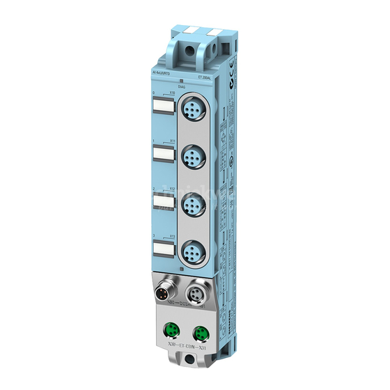
Page 12: Operator Controls And Display Elements
Product overview 2.2 Operator controls and display elements Operator controls and display elements The figure below shows the operator control and display elements of the interface module IM 157-1 DP. ① RUN, ERROR, MAINT: LED displays for the current operating status and diagnostics status ②... -
Page 13: Functions
DP master and the DP slaves. Reference You will find more information on PROFIBUS DP in the STEP 7 online help and in the Function Manual PROFIBUS with STEP 7 V13 (http://support.automation.siemens.com/WW/view/en/59193579). IM 157-1 DP (6ES7157-1AA00-0AB0) Equipment Manual, 08/2021, A5E32100641-AE... -
Page 14: Configuration Control (Option Handling)
Reference You can find more information on configuration control • In the system manual ET 200AL Distributed I/O System (https://support.industry.siemens.com/cs/ww/en/view/89254965) • On the Internet under the following link: Application collection (https://support.industry.siemens.com/cs/ww/en/view/29430270). • In the STEP 7 online help. -
Page 15: Wiring
Wiring Terminal and block diagram The image below shows the terminal and block diagram of the IM 157-1 DP interface module. ① Electronics Supply voltage 1L+ (non-switched) ② ET-Connection interface Ground 1M (non-switched) ③ Internal supply voltage Load voltage 2L+ (switched) ④... -
Page 16: Pin Assignment
Wiring 3.2 Pin assignment Pin assignment Note Color coding The sockets for ET-Connection and the power supply of the modules are color-coded. These colors correspond to the colors of the offered cables. Pin assignment of the sockets for PROFIBUS The following table shows the pin assignment of the connectors and sockets for the connection of PROFIBUS. - Page 17 Wiring 3.2 Pin assignment Pin assignment of the connector for infeed of the supply voltage The following table shows the pin assignment of the connector for infeed of the supply voltage. Table 3- 3 Pin assignment of the supply voltage connector Assignment Assignment of the Front view of the...
-
Page 18: Configuring Profibus Dp Address And Terminating Resistor
Wiring 3.3 Configuring PROFIBUS DP address and terminating resistor Configuring PROFIBUS DP address and terminating resistor Properties Use the PROFIBUS address to specify at which address the ET 200AL distributed I/O system is addressed on the PROFIBUS DP. The PROFIBUS DP address is configured for the ET 200AL distributed I/O system with a rotary coding switch on the front of the housing. - Page 19 Wiring 3.3 Configuring PROFIBUS DP address and terminating resistor Setting the PROFIBUS DP address Configurable PROFIBUS DP addresses are 1 to 99. Proceed as follows to configure the PROFIBUS DP address: 1. Remove the two M12 sealing caps from the rotary coding switches (use 14 mm socket wrench, if needed).
- Page 20 Wiring 3.3 Configuring PROFIBUS DP address and terminating resistor The following table shows how to set PROFIBUS address 26 as an example. Table 3- 5 Setting of the PROFIBUS address Tens digit Position 2 Ones digit Position 6 Connecting the terminating resistor for PROFIBUS DP Terminate a PROFIBUS DP segment, on both of its ends, which means on the first and last device of the segment, with its characteristic impedance.
-
Page 21: Parameters
Parameters Parameters The following table shows the parameters for the IM 157-1 DP interface module. Table 4- 1 Parameters Parameters Value range Default Efficiency range Configuration control Disable ET 200AL • Disable • Enable Startup if preset configuration does Disable ET 200AL •... - Page 22 Parameters 4.2 Explanation of the parameters Note Configuring the enable If you configure the enable, the ET 200AL distributed I/O system requires a control data record 196 from the user program in order for the ET 200AL distributed I/O system to operate the I/O modules.
-
Page 23: Interrupts, Error Messages, Diagnostics And System Alarms
Interrupts, error messages, diagnostics and system alarms Status and error displays LED displays The figure below shows the LED displays (status and error displays) of the IM 157-1 DP interface module. ① (green) ② ERROR (red) ③ MAINT (yellow) ④ ET-CON1 (green) ⑤... - Page 24 Interrupts, error messages, diagnostics and system alarms 5.1 Status and error displays Meaning of the LEDs The following tables set out the meaning of the status and error displays. Corrective measures for diagnostics alarms can be found in the section Diagnostics alarms (Page 34). LED RUN, LED ERROR, LED MAINT Table 5- 1 Status and error displays of the LEDs RUN, ERROR, MAINT...
- Page 25 Interrupts, error messages, diagnostics and system alarms 5.1 Status and error displays DP LED Table 5- 2 Status display of the DP LED DP LED Meaning Solution There is no connection between the Check whether the bus cable to the DP PROFIBUS interface of your PROFIBUS master is disconnected.
-
Page 26: Interrupts
Interrupts, error messages, diagnostics and system alarms 5.2 Interrupts Interrupts 5.2.1 Evaluating interrupts Introduction With certain process statuses/errors, the DP slave in each case creates an interrupt block with the corresponding information in the diagnostics frame (DPV1 interrupt mechanism). Regardless of this, the diagnostic status of the DP slave is displayed in the identifier-related diagnostics, in the module status, and in the channel diagnostics. -
Page 27: Triggering An Insert/Remove Module Interrupt
Interrupts, error messages, diagnostics and system alarms 5.2 Interrupts 5.2.4 Triggering an insert/remove module interrupt When an insert/remove module interrupt occurs, the CPU interrupts execution of the user program and processes the insert/remove module interrupt OB (OB 83). The event that triggered the interrupt is entered in the start information of the insert/remove OB. - Page 28 Interrupts, error messages, diagnostics and system alarms 5.2 Interrupts The figure below shows the structure of data record 1. Figure 5-3 Structure of data record 1 Reading data records You have the option to read out data records 0 and 1 via SFC 59 (RD_REC) or SFB 52 (RDREC). The data length of data record 1 is up to 240 bytes.
- Page 29 Interrupts, error messages, diagnostics and system alarms 5.2 Interrupts Contents The contents of the interrupt information depend on the interrupt type: • In the case of diagnostics interrupts, diagnostics data record 1 (up to 58 bytes) is sent as interrupt status information (starting from byte x+4). •...
- Page 30 Interrupts, error messages, diagnostics and system alarms 5.2 Interrupts Diagnostics interrupt, byte x+4 to x+7 The figure below shows the structure of the diagnostics interrupt of byte x+4 to byte x+7. Figure 5-5 Structure of bytes x+4 to x+7 for diagnostics interrupt IM 157-1 DP (6ES7157-1AA00-0AB0) Equipment Manual, 08/2021, A5E32100641-AE...
- Page 31 Interrupts, error messages, diagnostics and system alarms 5.2 Interrupts Diagnostics interrupt, starting at byte x+8 The figure below shows the structure of the diagnostics interrupt starting at byte x+8. Figure 5-6 Structure starting at byte x+8 Diagnostics interrupt from the modules, starting at byte x+14 The channel error entries start from byte x+14.
- Page 32 Interrupts, error messages, diagnostics and system alarms 5.2 Interrupts The following table is used to explain the channel error entries. Description Channel number 0 … 63: Channel number for channel error 0x8000: Entire submodule Channel properties Bits 0 to 7 : Free data type : bit : 2 bit...
- Page 33 Interrupts, error messages, diagnostics and system alarms 5.2 Interrupts Example of a diagnostics interrupt The figure below shows an example of a diagnostics interrupt. Figure 5-8 Example of a diagnostics interrupt (part 1) IM 157-1 DP (6ES7157-1AA00-0AB0) Equipment Manual, 08/2021, A5E32100641-AE...
- Page 34 Interrupts, error messages, diagnostics and system alarms 5.2 Interrupts Figure 5-9 Example of a diagnostics interrupt (part 2) Hardware interrupt of digital and analog input modules, bytes x+4 to x+7 The figure below shows the structure of a hardware interrupt. Figure 5-10 Structure as of Byte x+4 for hardware interrupt Note...
-
Page 35: Alarms
Interrupts, error messages, diagnostics and system alarms 5.3 Alarms Alarms 5.3.1 Diagnostics alarms Actions after a diagnostics alarm in DPV1 mode The error is entered in the channel diagnostics in the diagnostics frame: • In DPV1 mode, diagnostics can be reported as diagnostics interrupts. •... -
Page 36: Slave Diagnostics
Interrupts, error messages, diagnostics and system alarms 5.3 Alarms 5.3.2 Slave diagnostics The figure below shows the structure of the slave diagnostics. Figure 5-11 Structure of the slave diagnostics Note The length of the diagnostics frame varies with the IM 157-1 DP (depending on parameter assignment) between 6 and 244 bytes in DPV1 mode. -
Page 37: Station Statuses 1 To 3
Interrupts, error messages, diagnostics and system alarms 5.3 Alarms 5.3.3 Station statuses 1 to 3 The following tables show station status 1 to 3 and provide an overview of the status of a DP slave. Structure of station status 1 (byte 0) Table 5- 5 Structure of station status 1 (byte 0) Meaning... -
Page 38: Master Profibus Address
Interrupts, error messages, diagnostics and system alarms 5.3 Alarms Structure of station status 2 (byte 1) Table 5- 6 Structure of station status 2 (byte 1) Meaning 1: The DP slave parameters need to be reassigned. 1: A diagnostics alarm is pending. The DP slave will not operate until the problem is elim- inated (static diagnostics alarm). -
Page 39: Identifier-Related Diagnostics
Interrupts, error messages, diagnostics and system alarms 5.3 Alarms 5.3.6 Identifier-related diagnostics The identifier-related diagnostics indicates whether modules of the ET 200AL distributed I/O system have errors or not. Identifier-related diagnostics starts at byte 6 and comprises 6 bytes. The figure below shows how the identifier-related diagnostics for the ET 200AL distributed I/O system is structured with the IM 157-1 DP interface module. -
Page 40: Module Status
Interrupts, error messages, diagnostics and system alarms 5.3 Alarms 5.3.7 Module status The module status indicates the status of the configured modules and provides more information on the identifier-related diagnostics with respect to the configuration. The module status begins after the identifier-related diagnostics and comprises 13 bytes. The figure below shows how the module status for the ET 200AL distributed I/O system is structured with the IM 157-1 DP interface module. -
Page 41: Channel Diagnostics
Interrupts, error messages, diagnostics and system alarms 5.3 Alarms 5.3.8 Channel diagnostics Function Channel diagnostics provides information about channel errors in modules and details of the identifier-related diagnostics. Channel diagnostics begins after the module status. Channel diagnostics does not affect the module status. The figure below shows how the channel diagnostics for the ET 200AL distributed I/O system is structured with the IM 157-1 DP interface module. -
Page 42: Technical Specifications
Technical specifications of the interface module IM 157-1 DP The following table shows the technical specifications as of the issue date. You can find a data sheet including daily updated technical specifications on the Internet (https://support.industry.siemens.com/cs/ww/en/pv/6ES7157-1AA00-0AB0/td?dl=en). Article number 6ES7157-1AA00-0AB0 General information... - Page 43 Technical specifications Article number 6ES7157-1AA00-0AB0 1. Interface Interface type PROFIBUS DP Interface types • RS 485 Yes; 2x M12 B-coded • M12 port Protocols • PROFIBUS DP slave Interface types RS 485 12 Mbit/s • Transmission rate, max. PROFIBUS DP Services –...
- Page 44 Technical specifications Article number 6ES7157-1AA00-0AB0 Highest safety class achievable for safety- related tripping of standard modules PL d • Performance level according to ISO 13849- Cat. 3 • Category according to ISO 13849-1 SILCL 2 • SILCL according to IEC 62061 Ambient conditions Ambient temperature during operation -30 °C...
-
Page 45: Dimension Drawing
Dimension drawing The figure below shows the dimension drawing of the IM 157-1 DP interface module in the front and side view. Figure A-1 Dimension drawing IM 157-1 DP (6ES7157-1AA00-0AB0) Equipment Manual, 08/2021, A5E32100641-AE... -
Page 46: Cycle Times
Cycle times The following figure shows the cycle times at ET-Connection based on the number of I/O modules. Figure B-1 Cycle times The cycle time is independent of the PROFIBUS transmission rate. IM 157-1 DP (6ES7157-1AA00-0AB0) Equipment Manual, 08/2021, A5E32100641-AE...