Siemens SIMATIC ET 200AL Manual
Interface module im 157-1 pn
Hide thumbs
Also See for SIMATIC ET 200AL:
- System manual (2255 pages) ,
- Manual (86 pages) ,
- Equipment manual (46 pages)
Table of Contents
Advertisement
Advertisement
Table of Contents

Related Manuals for Siemens SIMATIC ET 200AL


Summary of Contents for Siemens SIMATIC ET 200AL
- Page 2 ___________________ Preface ___________________ Documentation guide ___________________ SIMATIC Product overview ___________________ Wiring ET 200AL Interface module IM 157-1 PN ___________________ (6ES7157-1AB00-0AB0) Parameters ___________ Interrupts, error messages, diagnostics and system Manual alarms ___________________ Technical specifications ___________________ Dimension drawing ___________________ Cycle times 12/2016 A5E32347036-AD...
- Page 3 Note the following: WARNING Siemens products may only be used for the applications described in the catalog and in the relevant technical documentation. If products and components from other manufacturers are used, these must be recommended or approved by Siemens. Proper transport, storage, installation, assembly, commissioning, operation and maintenance are required to ensure that the products operate safely and without any problems.
-
Page 4: Preface
In order to protect plants, systems, machines and networks against cyber threats, it is necessary to implement – and continuously maintain – a holistic, state-of-the-art industrial security concept. Siemens’ products and solutions only form one element of such a concept. Customer is responsible to prevent unauthorized access to its plants, systems, machines and networks. -
Page 5: Table Of Contents
Table of contents Preface ..............................4 Documentation guide ..........................6 Product overview ............................ 8 Properties ..........................8 Operator controls and display elements ................. 10 Functions ..........................11 2.3.1 PROFINET IO ......................... 11 2.3.2 PROFIenergy .......................... 14 2.3.2.1 What is PROFlenergy? ......................14 2.3.2.2 Principle of operation ...................... -
Page 6: Documentation Guide
Documentation guide The documentation for the SIMATIC ET 200AL distributed I/O system is arranged into three areas. This arrangement enables you to access the specific content you require. Basic information The System Manual and Getting Started describe in detail the configuration, installation, wiring and commissioning of the SIMATIC ET 200AL distributed I/O system. - Page 7 You must register once to use the full functionality of "mySupport". You can find "mySupport" on the Internet (https://support.industry.siemens.com/My/ww/en). "mySupport" - Documentation In the Documentation area in "mySupport" you can combine entire manuals or only parts of these to your own manual.
-
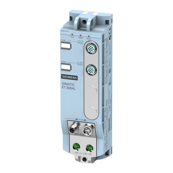
Page 8: Product Overview
Product overview Properties Article number 6ES7157-1AB00-0AB0 View of the module Figure 2-1 View of the IM 157-1 PN interface module Properties The module has the following technical properties: ● Connects the ET 200AL distributed I/O system with PROFINET IO ● 24 V DC supply voltage ●... - Page 9 ● M12 sealing cap See also You will find additional information on accessories and the other components in the Accessories/Spare parts section of the ET 200AL Distributed I/O System (http://support.automation.siemens.com/WW/view/en/89254965) system manual. Interface module IM 157-1 PN (6ES7157-1AB00-0AB0) Manual, 12/2016, A5E32347036-AD...
-
Page 10: Operator Controls And Display Elements
Product overview 2.2 Operator controls and display elements Operator controls and display elements The figure below shows the operator control and display elements of the interface module IM 157-1 PN. ① RUN, ERROR, MAINT: LED displays for the current operating status and diagnostics status ②... -
Page 11: Functions
Product overview 2.3 Functions Functions 2.3.1 PROFINET IO Introduction The interface module supports the following PROFINET IO functions: ● Integrated switch with 2 ports ● Supported Ethernet services: ping, arp, network diagnostics (SNMP)/MIB-2, LLDP ● Port diagnostics ● Deactivating of ports ●... - Page 12 Product overview 2.3 Functions Requirements The following table shows the software requirements for the use of PROFINET IO functions with the IM 157-1 PN interface module. Table 2- 1 Software requirements for PROFINET IO functions PROFINET IO function Configuration software STEP 7 (TIA Portal) V13 or STEP 7 V5.5 SP4 or higher higher...
- Page 13 IO device to the delivery state with "Reset to factory settings". You will find more information on "Resetting to factory settings" in the ET 200AL Distributed I/O System (http://support.automation.siemens.com/WW/view/en/89254965) system manual in the section "Resetting interface module (PROFINET) to factory settings".
-
Page 14: Profienergy
Product overview 2.3 Functions 2.3.2 PROFIenergy 2.3.2.1 What is PROFlenergy? Introduction PROFIenergy is a PROFINET-based data interface which makes it possible to switch off consumers in a coordinated and centrally controlled manner during break times regardless of the manufacturer or device. This has the aim that the process is only provided with the energy that is absolutely required. - Page 15 (https://support.industry.siemens.com/cs/ww/en/ps/14247/man) ● System manual PROFINET System Description (https://support.industry.siemens.com/cs/ww/en/view/19292127) ● PROFINET with STEP 7 V14 (https://support.industry.siemens.com/cs/ww/en/view/49948856), function manual, section: Saving energy with PROFIenergy ● Application guide for implementation of shutdown concepts with PROFIenergy. (https://support.industry.siemens.com/cs/ww/en/view/96837137) ● Saving energy with SIMATIC S7 (STEP 7 as of V5.5) (https://support.industry.siemens.com/cs/ww/en/view/41986454)
-
Page 16: Principle Of Operation
Product overview 2.3 Functions 2.3.2.2 Principle of operation "Pause" control and "Pause" behavior At the beginning/end of pauses, enable/disable the pause function on the system; the IO controller then sends the PROFIenergy command "Start_Pause" or "End_Pause" to the modules. The module then interprets the content of the PROFIenergy command and turns it off or on again. - Page 17 Product overview 2.3 Functions Hardware interrupt Ending a "Pause" causes hardware interrupts to be detected again. "Pause" behavior under certain operating conditions A "Pause" is ended in the following cases: Table 2- 2 Ending a "Pause" Ending a "Pause" Explanation The supply voltage 1L+ of the interface module module The "pause"...
-
Page 18: Parameter Assignment
Product overview 2.3 Functions 2.3.2.3 Parameter assignment Parameter assignment Keep the following points in mind when assigning parameters for PROFIenergy: ● Parameters for PROFIenergy are assigned with the parameter data record (version 2), index 3. The interface module distributes the PROFIenergy parameters to the I/O modules. - Page 19 Product overview 2.3 Functions Parameter data record You specify in the parameter data record for PROFIenergy which I/O modules (slots) are controlled with the PROFIenergy commands. The following table shows the content of the parameter data record for PROFIenergy, index 3, which you create yourself and can transfer to the interface module.
-
Page 20: Profienergy Control Data Records
Reference You can find more information on configuration control ● In the system manual ET 200AL Distributed I/O System (https://support.industry.siemens.com/cs/ww/en/view/89254965) ● On the Internet under the following link: Application collection (https://support.industry.siemens.com/cs/ww/en/view/29430270). ● In the STEP 7 online help. -
Page 21: Wiring
Wiring Terminal and block diagram The image below shows the terminal and block diagram of the IM 157-1 PN interface module. ① Switch Supply voltage 1L+ (non-switched) ② Electronics Ground 1M (non-switched) ③ ET-Connection interface Load voltage 2L+ (switched) ④ Internal supply voltage Ground 2M (switched) X1 P1 R... -
Page 22: Pin Assignment
Wiring 3.2 Pin assignment Pin assignment Note Color coding The sockets for ET-Connection and the power supply of the modules are color-coded. These colors correspond to the colors of the offered cables. Pin assignment of the sockets for PROFINET The following table shows the pin assignment of the two sockets for PROFINET. Table 3- 1 Pin assignment of the PROFINET sockets Assignment... - Page 23 Wiring 3.2 Pin assignment Pin assignment of the sockets for ET-Connection The table below shows the pin assignments of the 2 sockets for the connection of ET-Connection. Table 3- 2 Pin assignment for ET-Connection Assignment Assignment of Front view of the sockets the wire color of X30 socket X31 socket...
- Page 24 Wiring 3.2 Pin assignment NOTICE ET-Connection/supply voltage Observe the correct wiring of the M8 sockets for ET-Connection and the supply voltage. Mixing up the ET-Connection connectors and the connectors for the supply voltage can destroy the module. CAUTION PROFINET IO Modules with PROFINET interfaces may only be operated under the following condition: All connected devices must be equipped with SELV/PELV power supplies.
-
Page 25: Parameters
Parameters Parameters The following table shows the parameters for the IM 157-1 PN interface module. Table 4- 1 Parameters (GSD file) Parameters Value range Default Efficiency range Configuration control Disable ET 200AL Disable • Enable • Explanation of the parameters Configuration control You can use this parameter to enable the configuration control function in the ET 200AL distributed I/O system. -
Page 26: Interrupts, Error Messages, Diagnostics And System Alarms
Interrupts, error messages, diagnostics and system alarms Status and error displays LED displays The figure below shows the LED displays (status and error displays) of the interface module IM 157-1 PN. ① (green) ② ERROR (red) ③ MAINT (yellow) ④ ET-CON1 (green) ⑤... - Page 27 Interrupts, error messages, diagnostics and system alarms 5.1 Status and error displays Meaning of the LEDs The following tables set out the meaning of the status and error displays. Corrective measures for diagnostics alarms can be found in the section Diagnostics alarms (Page 30). LED RUN, LED ERROR, LED MAINT Table 5- 1 Status and error displays of the LEDs RUN, ERROR, MAINT...
- Page 28 Interrupts, error messages, diagnostics and system alarms 5.1 Status and error displays LED P1 LINK, LED P2 LINK Table 5- 2 Status displays of the LEDs P1 LINK and P2 LINK LEDs Meaning Solution P1 LINK P2 LINK There is no connection between the Check whether the bus cable to the switch PROFINET interface of your PROFINET or IO controller is disconnected.
-
Page 29: Interrupts
Independent of the cyclic user program, messages are made available on the display of the CPU S7-1500, the CPU web server and the HMI device. You will find more information on systemic diagnostics in the Function Manual Diagnostics (http://support.automation.siemens.com/WW/view/en/59192926). 5.2.2 Trigger a diagnostics interrupt... -
Page 30: Triggering A Hardware Interrupt
Interrupts, error messages, diagnostics and system alarms 5.3 Alarms 5.2.3 Triggering a hardware interrupt During a hardware interrupt, the CPU interrupts the processing of the user program and processes the hardware interrupt OB (e.g., OB 40). The event that triggered the interrupt is entered in the start information of the hardware interrupt OB. - Page 31 (http://support.automation.siemens.com/WW/view/en/24000238). Causes of error and troubleshooting Causes of errors and corrective measures of diagnostics alarms are described in the device manuals of the I/O modules (http://support.automation.siemens.com/WW/view/en/89013554) in the section Interrupt, Error and System Messages. Interface module IM 157-1 PN (6ES7157-1AB00-0AB0)
-
Page 32: Maintenance Events
Interrupts, error messages, diagnostics and system alarms 5.3 Alarms 5.3.2 Maintenance events Triggering of a maintenance event The PROFINET IO interfaces of the interface module support the diagnostics concept and maintenance concept in PROFINET IO according to standard IEC 61158-6-10. The goal is the early recognition and correction of potential disruptions. -
Page 33: Channel Diagnostics
Interrupts, error messages, diagnostics and system alarms 5.3 Alarms 5.3.3 Channel diagnostics Function Channel-related diagnostics provides information about channel faults in modules. Channel faults are mapped as channel diagnostics data in IO diagnostics data records. The data record is read with the "RDREC" instruction (SFB 52). Structure of the diagnostics data records The data records supported by the ET 200AL distributed I/O system are based on the PROFINET IO standard - Application Layer Service definition V2.2. -
Page 34: Technical Specifications
Technical specifications Technical specifications of the interface module IM 157-1 PN 6ES7157-1AB00-0AB0 General information Product type designation IM 157-1 PN Hardware functional status Firmware version V1.0.x Vendor identifier (VendorID) 002AH Product function I&M data Yes; I&M0 to I&M4 Engineering with STEP 7 TIA Portal can be configured/integrated as of STEP 7 V13 SP1 as of version... - Page 35 Technical specifications 6ES7157-1AB00-0AB0 Protocols PROFINET IO device Interface hardware M12 port 10 Mbps Yes; for Ethernet services 100 Mbps Yes; PROFINET with 100 Mbps full duplex (100BASE-TX) Transmission method PROFINET with 100 Mbps full duplex (100BASE- Autonegotiation Autocrossing Protocols PROFINET IO device Services Open IE communication •...
- Page 36 Technical specifications 6ES7157-1AB00-0AB0 Degree of protection and protection class Degree of protection according to EN 60529 IP65 • IP67 • Ambient conditions Ambient temperature during operation Min. -25 °C Max. 55 °C Connection technology Power supply M8, 4-pin ET-Connection ET-Connection M8, 4-pin, shielded Dimensions Width...
-
Page 37: Dimension Drawing
Dimension drawing The figure below shows the dimension drawing of the IM 157-1 PN interface module in the front and side view. Figure A-1 Dimension drawing Interface module IM 157-1 PN (6ES7157-1AB00-0AB0) Manual, 12/2016, A5E32347036-AD... -
Page 38: Cycle Times
Cycle times The figure below shows the cycle times at ET-Connection based on the number of I/O modules with a Profinet send clock of 0.5ms. Figure B-1 Cycle times The cycle time at ET-Connection is synchronized with the PROFINET send clock. This means that the input data of the I/O modules are transmitted via ET-Connection without further delay (wait time in the interface module) via PROFINET.