Siemens SIMATIC ET 200AL Equipment Manual
Digital input module di 8x24vdc 4xm12
Hide thumbs
Also See for SIMATIC ET 200AL:
- System manual (2255 pages) ,
- Manual (86 pages) ,
- Equipment manual (46 pages)
Table of Contents
Advertisement
Quick Links
Advertisement
Table of Contents

Related Manuals for Siemens SIMATIC ET 200AL


Summary of Contents for Siemens SIMATIC ET 200AL
- Page 2 DI 8x24VDC 4xM12 (6ES7141-5AF00-0BA0) Preface ET 200AL Documentation Guide SIMATIC Product overview Wiring ET 200AL DI 8x24VDC 4xM12 Parameters/address space (6ES7141-5AF00-0BA0) Interrupts/diagnostic alarms Equipment Manual Technical specifications PROFIenergy Dimension drawing 08/2021 A5E36680963-AB...
- Page 3 Note the following: WARNING Siemens products may only be used for the applications described in the catalog and in the relevant technical documentation. If products and components from other manufacturers are used, these must be recommended or approved by Siemens. Proper transport, storage, installation, assembly, commissioning, operation and maintenance are required to ensure that the products operate safely and without any problems.
-
Page 4: Preface
Siemens' products and solutions undergo continuous development to make them more secure. Siemens strongly recommends that product updates are applied as soon as they are available and that the latest product versions are used. Use of product versions that are no longer supported, and failure to apply the latest updates may increase customers' exposure to cyber threats. -
Page 5: Table Of Contents
Table of contents Preface ..............................3 ET 200AL Documentation Guide ......................5 Product overview ........................... 9 Properties ..........................9 Operator controls and display elements ................11 Wiring ..............................12 Terminal and block diagram ....................12 Pin assignment ........................13 Parameters/address space ........................16 Parameters ........................ -
Page 6: Et 200Al Documentation Guide
This arrangement enables you to access the specific content you require. Basic information The System Manual and Getting Started describe in detail the configuration, installation, wiring and commissioning of the SIMATIC ET 200AL distributed I/O system. The STEP 7 online help supports you in the configuration and programming. Device information Product manuals contain a compact description of the module-specific information, such as properties, wiring diagrams, characteristics and technical specifications. - Page 7 You must register once to use the full functionality of "mySupport". You can find "mySupport" on the Internet (https://support.industry.siemens.com/My/ww/en). "mySupport" - Documentation With "mySupport", your personal workspace, you make the best out of your Industry Online Support.
- Page 8 You can find the SIMATIC Automation Tool on the Internet (https://support.industry.siemens.com/cs/ww/en/view/98161300). PRONETA SIEMENS PRONETA (PROFINET network analysis) allows you to analyze the plant network during commissioning. PRONETA features two core functions: • The topology overview automatically scans the PROFINET and all connected components.
- Page 9 ET 200AL Documentation Guide SINETPLAN SINETPLAN, the Siemens Network Planner, supports you in planning automation systems and networks based on PROFINET. The tool facilitates professional and predictive dimensioning of your PROFINET installation as early as in the planning stage. In addition, SINETPLAN supports you during network optimization and helps you to exploit network resources optimally and to plan reserves.
-
Page 10: Product Overview
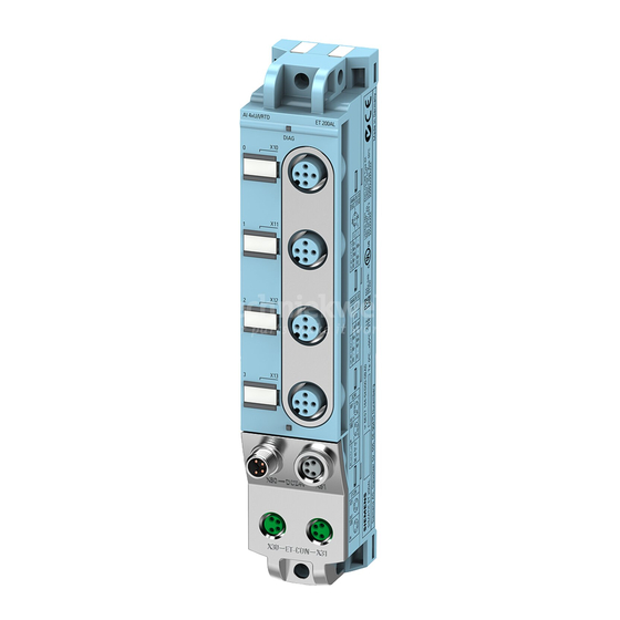
Product overview Properties Article number 6ES7141-5AF00-0BA0 View of the module Figure 2-1 View of the DI 8x24VDC 4xM12 digital input module DI 8x24VDC 4xM12 (6ES7141-5AF00-0BA0) Equipment Manual, 08/2021, A5E36680963-AB... - Page 11 • M8 sealing cap • M12 sealing cap See also You can find more information on accessories in the Accessories/spare parts section of the ET 200AL distributed I/O system (https://support.industry.siemens.com/cs/us/en/view/89254965) system manual. DI 8x24VDC 4xM12 (6ES7141-5AF00-0BA0) Equipment Manual, 08/2021, A5E36680963-AB...
-
Page 12: Operator Controls And Display Elements
Product overview 2.2 Operator controls and display elements Operator controls and display elements The figure below shows the operator controls and display elements of the DI 8x24VDC 4xM12 digital input module. ① DIAG: LED display for the diagnostic status ② X10 to X13: Sockets for the input signal ③... -
Page 13: Wiring
Wiring Terminal and block diagram The figure below shows an example of the pin assignment of signal inputs with 2-wire and 3-wire connection. ① 3-wire connection Infeed of the ET-Connection ② 2-wire connection Loop-through of the ET-Connection ③ 2-wire connection Supply voltage 1L+ (non-switched) ④... -
Page 14: Pin Assignment
Wiring 3.2 Pin assignment Pin assignment Note Color coding The sockets for ET-Connection and the power supply of the modules are color-coded. These colors correspond to the colors of the offered cables. Pin assignment of the sockets for digital inputs The table below shows the pin assignment of the 4 sockets for the connection of digital inputs. - Page 15 Wiring 3.2 Pin assignment Pin assignment of the sockets for ET-Connection The table below shows the pin assignments of the 2 sockets for the connection of ET-Connection. Table 3- 2 Pin assignment for ET-Connection Assignment Assignment of the Front view of the sockets wire color of the X30 socket X31 socket...
- Page 16 Wiring 3.2 Pin assignment Pin assignment of the socket for loop-through of the supply voltage The table below shows the pin assignment of the socket for loop-through of the supply voltage. Table 3- 4 Pin assignment of the supply voltage socket Assignment Assignment of the Front view of the...
-
Page 17: Parameters/Address Space
Parameters/address space Parameters The table below shows the parameters for the DI 8x24VDC 4xM12 digital input module. Table 4- 1 Parameters Parameters Value range Default Scope Diagnostics: Short-circuit to ground Disable Module • Disable • Enable Explanation of the parameters Diagnostics: Short-circuit to ground Enabling of the diagnostics if a short-circuit of the encoder supply to ground occurs. -
Page 18: Address Space
Parameters/address space 4.3 Address space Address space The figure below shows the assignment of the address space for the digital input module DI 8x24VDC 4xM12 with value status (Quality Information, QI). The address space for the value status is allocated by the module, if the value status is configured using the PROFINET interface module. -
Page 19: Interrupts/Diagnostic Alarms
Interrupts/diagnostic alarms Status and error displays LED displays The figure below shows the LED displays (status and error displays) of the DI 8x24VDC 4xM12 digital input module. ① Diagnostic status (DIAG) (red/green) ② Channel status (0 to 7) (green) Figure 5-1 LED displays DI 8x24VDC 4xM12 (6ES7141-5AF00-0BA0) Equipment Manual, 08/2021, A5E36680963-AB... - Page 20 Interrupts/diagnostic alarms 5.1 Status and error displays Meaning of the LEDs The following tables set out the meaning of the status and error displays. Corrective measures for diagnostics alarms can be found in section Diagnostics alarms (Page 20). DIAG LED Table 5- 1 Error display of the DIAG LED DIAG LED...
-
Page 21: Interrupts
Interrupts/diagnostic alarms 5.2 Interrupts Interrupts The DI 8x24VDC 4xM12 digital input module supports diagnostic interrupts. Diagnostic interrupt The digital input module generates a diagnostic interrupt at the following events: • Short-circuit of encoder supply to ground Diagnostics alarms For each diagnostic event, a diagnostics alarm is issued and the DIAG LED flashes red on the digital input module. -
Page 22: Technical Specifications
Technical specifications of the DI 8x24VDC 4xM12 digital input module The following table shows the technical specifications as of the issue date. You can find a data sheet including daily updated technical specifications on the Internet (https://support.industry.siemens.com/cs/ww/en/pv/6ES7141-5AF00-0BA0/td?dl=en). Article number 6ES7141-5AF00-0BA0... - Page 23 Technical specifications 6.1 Technical specifications Article number 6ES7141-5AF00-0BA0 Power loss Power loss, typ. 1.9 W Digital inputs Number of digital inputs Input characteristic curve in accordance with IEC 61131, type 3 Number of simultaneously controllable inputs all mounting positions – up to 55 °C, max.
- Page 24 Technical specifications 6.1 Technical specifications Article number 6ES7141-5AF00-0BA0 Potential separation channels • between the channels • between the channels and backplane bus • between the channels and the power sup- ply of the electronics Isolation Isolation tested with 707 V DC (type test) Standards, approvals, certificates Suitable for safety-related tripping of standard Yes;...
-
Page 25: Profienergy
Additional information You can find additional information on working with PROFIenergy in the "PROFIenergy" section of the manual IM 157-1 PN interface module (https://support.industry.siemens.com/cs/ww/en/view/89254863) and the "Saving energy with PROFIenergy" section of function manual PROFINET with STEP 7 V13 (https://support.industry.siemens.com/cs/ww/en/view/49948856). -
Page 26: Behavior Of The Digital Input Module
PROFIenergy 7.2 Behavior of the digital input module Behavior of the digital input module Display The channel status LEDs are directly influenced by the signal level at the socket. If the encoder supply is switched off, this causes the channel status LEDs to also switch off. Response to error detection All channels that are in pause mode on "PE_MODE_PROCEED"... -
Page 27: Dimension Drawing
Dimension drawing The figure below shows the dimension drawing of the DI 8x24VDC 4xM12 digital input module in front and side view. Figure A-1 Dimension drawing DI 8x24VDC 4xM12 (6ES7141-5AF00-0BA0) Equipment Manual, 08/2021, A5E36680963-AB...