Table of Contents
Advertisement
Quick Links
Advertisement
Table of Contents
Troubleshooting

Related Manuals for Fujitsu ETERNUS LT160


Summary of Contents for Fujitsu ETERNUS LT160
- Page 1 C144-E072-01EN Tape Library User's Guide...
- Page 3 OPERATION" Use the product according to the instructions and information available in this manual. Keep this manual handy for further reference. Fujitsu makes every effort to prevent users and bystanders from being injured or damage to their property. Use the product according to this manual.
- Page 4 IEC = International Electrical for Commission JTC1 = Joint Technical Committee 1 The contents of this manual shall not be disclosed in any way or reported in any media without the express written permission of Fujitsu Limited. All Rights Reserved, Copyright© FUJITSU LIMITED 2002 C144-E072-01EN...
- Page 5 Revision History (1/1) Edition Date Revised location (type) (*1) Revision October 15, 2002 *1 Items in the "Revised location" column refer to the latest edition unless the item is marked with an asterisk. An asterisk indicates an item in an older edition. C144-E072-01EN...
-
Page 7: Preface
Preface This manual describes the LT160 magnetic tape library. This manual first provides an overview of the tape library and then detailed information about the tape library. The detailed information includes specifications, installation requirements and procedures for incorporating the tape library into a system, and information about how to clean the tape library. - Page 8 Preface Chapter 7 Cartridge Media and Bar Code Label Specifications This chapter provides information on Ultrium cartridges and cleaning cartridges, handling of cartridges, bar code label specifications, and maintenance and the service life of cartridges. Appendix A Model Configurations This appendix provides a the diagram of the configuration of each library. Appendix B Technical Specifications This appendix provides ambient environment, library, physical, and Fibre Channel cable specifications.
- Page 9 Notice If any information in this manual is unclear or incorrect, please complete the comment form at the back of this manual and give it to a Fujitsu systems engineer or salesperson. The contents of this manual may be revised without prior notice.
-
Page 11: Important Alert Items
Important Alert Items Important Alert Messages The important alert messages in this manual are as follows: A hazardous situation could result in minor or moderate personal CAUTION injury if the user does not perform the procedure correctly. Also, damages to the product or other property, may occur if the user does not perform the procedure correctly. - Page 12 Important Alert Items Task Alert message Page Normal operation 4-40 Data loss: If a drive is used for the load/unload operation, the drive cannot be used from backup software. Be sure to stop the operation of backup software before performing the load/unload operation. Cleaning 4-41 Data loss:...
-
Page 13: Important Information On Handling
A manifest form (waste management form) must be issued when it is to be disposed of. If you request that Fujitsu dispose of the tape library, Fujitsu's affiliate logistics company (company permitted to collect and transport industrial waste) will pick the tape library up. - Page 14 Important Information on Handling Eco Center of Fujitsu Logistics (Telephone: 045-470-5305) Fujitsu Recycle System, which has constructed Fujitsu's recycling system, disassembles used products at its recycle center and segregates components for reuse or recycles them as materials. Disposal of magnetic tape Handle magnetic tape that is disposed of as described in "Request for collecting and...
-
Page 15: Manual Organization
Manual Organization Manual Organization Magnetic Tape Library User's Overview Guide (C144-E072) Introducing and Preparing the Library (This Manual) Library Operation Operator Panel Operation Remote Panel Operation Troubleshooting Cartridge Media and Bar Code Label Specifications Magnetic Tape Library Setup Overview Guide (C144-E073) Setting Up the Tape Library Setting the Fibre Channel Interface Setting the Operating System... -
Page 17: Table Of Contents
Contents Preface........................i Important Alert Items ....................v Important Information on Handling ............... vii Manual Organization....................ix Contents.........................xi Chapter 1 Overview .................... 1-1 1.1 Device Configuration ..................1-1 1.1.1 Device outline..................1-1 1.1.2 Robot ....................1-4 1.1.3 Each component of the library............1-7 1.1.3.1 Configuration of the basic model components ..... -
Page 18: Contents
Contents 1.2.8 E-mail function................. 1-35 1.2.9 SNMP function................. 1-36 Chapter 2 Introducing and Preparing the Library ..........2-1 2.1 Installing the Library..................2-1 2.1.1 Conditions for library installation ............2-1 2.2 Preparing the Host Installation................ 2-4 2.3 Connecting the Library ................... 2-5 2.4 Power-on and Power-off ................. - Page 19 Contents 4.3.3 Referencing setup information for the library ........4-20 4.3.4 Referencing information about the drive .......... 4-20 4.3.5 Referencing setup information for the network ........ 4-22 4.3.6 Referencing error information ............4-22 4.3.6.1 Referencing hardware error information for the library ..4-22 4.3.6.2 Referencing hardware error information for the drive ..
- Page 20 Contents 5.5.5 Setting the e-mail function ............... 5-38 5.5.6 Setting the SNMP agent ..............5-40 5.5.7 Changing the password ..............5-42 5.6 Operating the Library..................5-43 5.6.1 Cleaning the drive manually ............5-43 5.6.2 Operating the trace file..............5-45 5.6.3 Saving setup information for the library/drive ......... 5-46 5.6.4 Restoring setup information for the library/drive......
- Page 21 Contents A.3 Model Configuration of Basic Model A20 (10 drive options/221 cell options/10 CASs) ..................A-4 A.4 Model Configuration of Basic Model A32 (16 drive options/89 cell options/10 CASs) ..................A-5 A.5 Model Configuration of Basic Model A32 (16 drive options/167 cell options/10 CASs) ..................
- Page 23 Contents Illustrations Figure Figure 1.1 Appearance (front)................1-1 Figure 1.2 Appearance (rear) ................1-2 Figure 1.3 Appearance (rear: with the open rear door) ........1-3 Figure 1.4 Appearance (isometric view from left: with left side board removed) ..................1-3 Figure 1.5 Hand mechanism ................
- Page 24 Contents Figure 4.7 Reference window for magazine cell cartridge information ..4-13 Figure 4.8 Reference window for cleaning cell cartridge information ....4-14 Figure 4.9 Reference window for reserve cell cartridge information ....4-15 Figure 4.10 Cartridge information reference window for diagnostic cell..4-16 Figure 4.11 Selecting the [Host I/F] button ............4-17 Figure 4.12...
- Page 25 Contents Figure 5.28 E-mail function setting window............. 5-38 Figure 5.29 SNMP agent setting window ............5-40 Figure 5.30 Password change window.............. 5-42 Figure 5.31 Manual cleaning operation window..........5-44 Figure 5.32 Trace file operation window ............5-45 Figure 5.33 Library/drive setup information save window ....... 5-46 Figure 5.34 Confirming that library/drive setup information has been downloaded..................
- Page 26 Contents Table Table 1.1 Configuration list of model elements ..........1-9 Table 1.2 Upgrade pattern (A20) ..............1-9 Table 1.3 Upgrade pattern (A32) ..............1-9 Table 4.1 Library status..................4-9 Table 4.2 Drive/Cartridge.................4-9 Table 4.3 Drive/cartridge status (added to the end of indications of library or drive statuses listed in Table 4.2) ..........4-10 Table 4.4 LOOP ID/ALPA correspondence table ..........4-27...
-
Page 27: Chapter 1 Overview
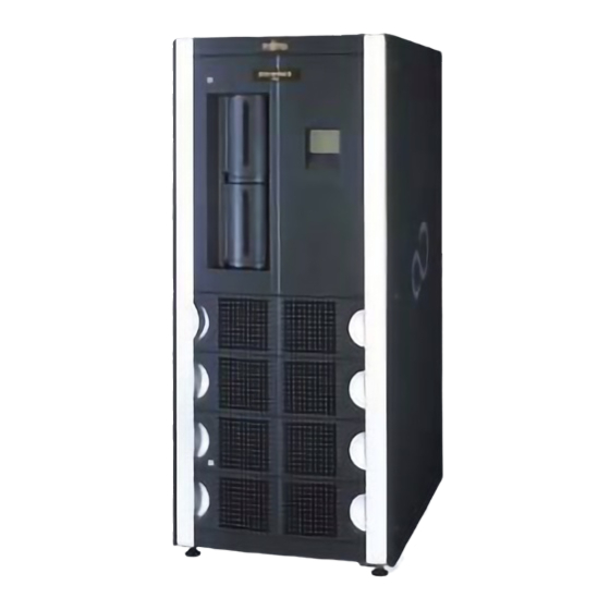
Chapter 1 Overview Device Configuration Functional Overview Device Configuration 1.1.1 Device outline Figure 1.1 Appearance (front) (1) Front door (2) Rear door (3) Operator panel (4) Window (5) CAS (Cartridge Access Station) (6) Key C144-E072-01EN... -
Page 28: Figure 1.2 Appearance (Rear)
Overview Figure 1.2 Appearance (rear) (1) Key (2) Power switch C144-E072-01EN... -
Page 29: Figure 1.3 Appearance (Rear: With The Open Rear Door)
1.1 Device Configuration Figure 1.3 Appearance (rear: with the open rear door) (1) Drive module Figure 1.4 Appearance (isometric view from left: with left side board removed) (1) Robot unit C144-E072-01EN... -
Page 30: Robot
Overview 1.1.2 Robot The robot is used for transporting a tape cartridge from cell to cell, or from cell and CAS (See 1.1.4 "Cartridge Access Station (CAS)) to the drive". Figure 1.6 shows the appearance of the robot unit. (1) Hand mechanism Mechanism for ejecting or inserting cartridges from or into a cell, CAS, or drive. - Page 31 1.1 Device Configuration CM reader: Reads the cartridge memory information contained in a cartridge. CIC sensor: Identifies whether a cartridge is in the cell, CAS, or drive. CIP sensor: Indicates whether there is a cartridge in the hand mechanism. (2) Tilt mechanism Mechanism for tilting the hand mechanism to 0 degree and 12 degrees.
-
Page 32: Figure 1.6 Robot Appearance
Overview Figure 1.6 Robot appearance (1) Hand mechanism (For details, see Figure 1.5) (2) Tilt mechanism (3) Swivel mechanism (4) X mechanism (5) Y mechanism C144-E072-01EN... -
Page 33: Each Component Of The Library
1.1 Device Configuration 1.1.3 Each component of the library This section explains the physical location of each element in the library, namely, the cell, drive, and CAS (Cartridge Access Station) and their element addresses. Remarks: For information on the configuration diagram of each model, see Appendix A, "Model Configuration."... -
Page 34: Special Cells
Overview 1.1.3.2 Special cells In the library, there are special cells that cannot be accessed from the host. The number of cells of each type depends on the model. COLUMN - 5 Includes the cleaning cell(5), replacement cell(1), reserve cell(2), and diagnostic cell(3). -
Page 35: Configuration And Upgrade Pattern For Each Model
1.1 Device Configuration 1.1.3.3 Configuration and upgrade pattern for each model The following shows the component configuration and the upgradable configuration for each model. Table 1.1 Configuration list of model elements Option Power Number Locker Model supply Number of of CASs Number of used drivers... -
Page 36: Cartridge Access Station (Cas)
Overview 1.1.4 Cartridge Access Station (CAS) CAS is a mechanism through which the operator inserts or ejects cartridges when the device is operating. A special magazine is used for inserting or ejecting cartridges and up to five volumes of cartridges can be inserted/ejected simultaneously for each CAS. CAS consists of the following mechanisms. -
Page 37: Inserting A Magazine From Cas
1.1 Device Configuration (1) External door Door that covers the magazine insertion/ejection port. The external door is normally locked by covering the magazine insertion/ejection port. The external door can be unlocked by using an operation from the operator panel so that a magazine can be inserted or ejected. - Page 38 Overview Insertion Ejection Figure 1.9 Magazine insertion method 1 3) Make sure that the magazine is in its regular position and then close the external door until it is locked. 1-12 C144-E072-01EN...
- Page 39 1.1 Device Configuration Notes: The magazine is tilted while pushing it into CAS so that it rests on the positioning projection (Figure 1.10). If the magazine is pushed further, it is completely over the positioning projection (Figure 1.11). This state in which the magazine is pushed in completely is its regular position.
-
Page 40: Figure 1.11 Magazine Insertion Method 3 (Magazine Regular Position)
Overview Figure 1.11 Magazine insertion method 3 (magazine regular position) 1-14 C144-E072-01EN... -
Page 41: Ejecting A Magazine From Cas
1.1 Device Configuration 1.1.4.2 Ejecting a magazine from CAS 1) After the CAS external door is unlocked with an operation from the operator panel, the external door opens slightly. By hand, gently open the external door to the left until you hear a click. 2) Hold the handle on the rear side of the magazine inside CAS, lift the handle by holding it so that the magazine front is pointing downward and the bottom on the rear side is lifted... -
Page 42: Magazine
Overview 1.1.5 Magazine The magazine is used as a shelf unit for receiving/delivering cartridges inside CAS when the operator inserts/ejects cartridges via CAS. The magazine has a 5-shelf unit for storing cartridges and up to five volumes of cartridges can be inserted/ejected simultaneously from CAS. -
Page 43: Inserting Cartridges Into The Magazine
1.1 Device Configuration (4) CAS insertion/ejection handle This handle is used for pushing in/pulling out the magazine at insertion into or ejection from CAS. (5) Lever for preventing cartridges from being inserted backwards Lever to keep cartridges from being inserted backwards. If an attempt is made to insert a cartridge into the magazine with the cartridge having the wrong orientation, this lever is extended, making insertion into the CAS physically impossible. -
Page 44: Ejecting Cartridges From The Magazine
Overview Figure 1.15 Figure for explaining cartridge insertion method b Orientation of cartridges during insertion Set the orientation of the magazine so that the bar code label affixed to the cartridge rear side faces the front of the magazine and the bottom (surface with the hub) of the cartridge is pointing downward. -
Page 45: Drive Module
1.1 Device Configuration 1.1.6 Drive module The drive module is a module unit that contains the drive for recording data, drive power supply, and external interface. When, for example, a drive fails, maintenance replacement is carried out in units of drive modules. The host interface supports the fiber channel. - Page 46 Overview (2) Connection connector Connector for connecting a drive module and the main unit of the device. This connector is used for information management and power supply of the drive. (3) Relative position flag Mark for inserting cartridges into the drive with the robot. Remarks: Note that the robot may not be able to insert cartridges into the drive correctly due to deformation or dust adherence.
-
Page 47: Opening/Closing The Door
1.1 Device Configuration 1.1.7 Opening/Closing the door The following explains how to open and close the front door, internal door, and rear door. CAUTION Damage on the library and electrical shock: Be sure to open and close the front door and internal door after making sure that the device is turned off. - Page 48 Overview (1) Opening the front door 1) Turn to the open position the keys in the locked position at the upper and lower parts of the front door (two locations). 2) Open the front door by pulling the handle out. (2) Closing the front door 1) Close the front door by pressing the aluminum part at the left end of the front door.
-
Page 49: Opening And Closing The Internal Door
1.1 Device Configuration 1.1.7.2 Opening and closing the internal door (1) Thumbscrew (2) Handle (3) Internal door Figure 1.18 Internal door C144-E072-01EN 1-23... -
Page 50: Figure 1.19 Internal Door (When Open)
Overview (1) Opening the internal door 1) Keep the front door open. 2) Rotate the thumbscrews at the upper and lower parts of the door counterclockwise until they come off. 3) If the two screws come off, pull the handle out to open the internal door (Figure 1.19). -
Page 51: Opening And Closing The Rear Door
1.1 Device Configuration 1.1.7.3 Opening and closing the rear door Locked Open (1) Rear door (2) Handle Figure 1.20 Rear door C144-E072-01EN 1-25... -
Page 52: Figure 1.21 Rear Door (When Open)
Overview (1) Opening the rear door 1) Turn the rear door key from the locked position to the open position. 2) Pull the handle out to open the rear door (Figure 1.21). Figure 1.21 Rear door (when open) (2) Closing the rear door 1) Close the rear door slowly and turn the key to the locked position. -
Page 53: Hardware Module (Interface Card, Power Supply, And Bcr)
1.1 Device Configuration 1.1.8 Hardware module (interface card, power supply, and BCR) Drive power supply Robot power supply PDU section (10) (11) Remarks: Drive power supply (1) Power ON (green) (2) Power ALARM (orange) (3) Fan ALARM (orange) Figure 1.22 LED sections (device rear view) (1/2) C144-E072-01EN 1-27... -
Page 54: Figure 1.22 Led Sections (Device Rear View) (2/2)
Overview Robot power supply (4) Power ON (green) (5) Power ALARM (orange) (6) Fan ALARM (orange) PDU section (7) Power ON (green) (8) Robot side ALARM (orange) (9) Drive side ALARM (orange) (10) Robot side ON (green) (11) Drive side ON (green) Figure 1.22 LED sections (device rear view) (2/2) Figure 1.23 Cable insertion port (Lower part on the rear side of the device) (1) Interface between HOST and drive (FC) -
Page 55: Functional Overview
1.2 Functional Overview Functional Overview This section explains the functions provided by the magnetic tape library device (referred to as the library hereafter). 1.2.1 FC control function The library is controlled by software that controls a magnetic tape library device, such as backup software (collectively referred to as backup software hereafter). -
Page 56: Inventory Function
Overview 1.2.3 Inventory function This is a function for updating cartridge management information by reading the bar code labels affixed to the cartridges inside the library. The inventory function is used in the following cases: When the library is turned on (only if the auto-inventory function is "enabled") When the inventory is operated from the operator panel When the front door is opened and closed to insert or eject a large number of cartridges. -
Page 57: Manual Load Function
1.2 Functional Overview 1.2.4 Manual load function This is a function for loading cartridges directly to the drive from CAS or to unload them directly from the drive to CAS without using backup software. To load a cartridge to the drive or to unload it from the drive manually, perform the Load/Unload operation on the operator panel. -
Page 58: Manual Cleaning Function
Furthermore, the auto-cleaning function of the backup software uses ordinary cells, reducing the cells available for data cartridges. Fujitsu therefore recommends using the auto-cleaning function under control of the library (the factory default is "enabled"). -
Page 59: Functions For Recovery
1.2 Functional Overview 1.2.6 Functions for recovery This library takes into account settings and operations for recovery corresponding to errors of the drive, library, and server. 1.2.6.1 Recovery method when a drive error occurs If an error occurs in the drive during initialization or when a cartridge is loaded, "Error" is displayed in the "Drive Status"... -
Page 60: Auto-Eject Function
Overview Remarks: For information on the method of operating the manual ejection from the operator panel, see 4.12, "Unloading a Cartridge Loaded from the Host." CAUTION Data loss: Do not perform this operation when the host accesses the drive normally. Otherwise, an error may occur in the drive path. 1.2.6.4 Auto-eject function This function can unload all cartridges already loaded in the drive when the library is turned on (*1). -
Page 61: E-Mail Function
1.2 Functional Overview Remarks: 1. To use the remote panel, it is necessary to make network settings in advance from the operator panel. For information on the methods of network settings and operating the remote panel, see 5, "Remote Panel Operation." 2. -
Page 62: Snmp Function
Overview 1.2.9 SNMP function This library has the SNMP function linked to a system that manages hardware connected to a network. The SNMP function uses the SNMP protocol to transmit device information obtained via MIB and error information obtained via TRAP from the SNMP agent incorporated into the library to the management software. -
Page 63: Chapter 2 Introducing And Preparing The Library
Chapter 2 Introducing and Preparing the Library Installing the Library Preparing the Host Installation Connecting the Library Power-on and Power-off Checking the Library and Drive Settings Checking the Host Settings Installing the Library 2.1.1 Conditions for library installation In addition to the installation space of the device, space is required for opening and closing the front and rear doors. -
Page 64: Figure 2.1 Space Required For Library Installation
Introducing and Preparing the Library Device front Device top surface Leveling foot : 60 1130 : Maintenance area : Cable takeoff (intake) port : View area Figure 2.1 Space required for library installation If the customer uses the LT160-20 or LT160-30 and plans to implement expansion in the future, separate space for installing the expansion locker will also be required. -
Page 65: Figure 2.2 Removing Transport Metal Brackets
2.1 Installing the Library Figure 2.2 Removing transport metal brackets Transport metal brackets (1) Transport metal bracket 1 (2) Transport metal bracket 1 setscrews (two) (3) Transport metal bracket 2 (4) Transport metal bracket 2 setscrew (one) (5) Transport metal bracket 3 (6) Transport metal bracket 3 setscrews (three) C144-E072-01EN... -
Page 66: Preparing The Host Installation
Introducing and Preparing the Library Preparing the Host Installation This section explains how to prepare for host installation. Refer to the "Setup Guide" provided with the library for information about the settings for the host, OS, driver, software, and hardware required to use the library. Remarks: A host, host bus adapter, FC switch, or other devices to be connected to the library must be ones that support the library. -
Page 67: Connecting The Library
2.3 Connecting the Library Connecting the Library The library is connected via the Fibre Channel interface to a host server. The host server is a server (such as Solaris and WindowsNT4.0/2000) on which software that controls the library (backup software) is installed. The backup software requests the library or drive to transport cartridges or requests access to data. - Page 68 Introducing and Preparing the Library The following procedure explains the wiring of fiber channels among the host, hub/switch, and library. Remarks: To use a hub or switch, see the user's manual for the product to be used. 1) Make sure that the library and host are not active and the library is not connected to the host.
-
Page 69: Power-On And Power-Off
2.4 Power-on and Power-off Power-on and Power-off 2.4.1 Power-on method Press the power switch on the back panel to turn on the library or drive. The power-on method depends on whether RCI is used. 2.4.1.1 If RCI is not used Turn on the power switch located on the back panel on the rear of the library. -
Page 70: Power-Off Method
Introducing and Preparing the Library 2.4.2 Power-off method The power-off method for the library depends on whether RCI is used. Remarks: Before turning off the library, check that the operation is stopped and that no cartridge remains in the drives. Emergency power-off method If the power to the system must be turned off immediately in case of emergency, such as the occurrence of a library error, pull out the power... -
Page 71: Checking The Library And Drive Settings
2.5 Checking the Library and Drive Settings Checking the Library and Drive Settings From the operator panel or remote panel, check the settings of the drive and library being used. 2.5.1 Checking the drive settings A Fibre Channel Loop ID must be set for each drive. The factory default is "Soft Address."... -
Page 72: Checking The Fast Load Function Setting
Introducing and Preparing the Library 2.5.2.6 Checking the fast load function setting The fast load function enables the next mount operation during the current mount operation (without waiting for the drive to become ready) to speed up robot performance. The factory default is "disabled." For information on the setting method, see 4.5.2, "Setting library information."... -
Page 73: Checking The Host Settings
Perform backup on a trial basis to make sure that all the components are correctly set up. Remarks: For more information on setting or checking the driver of the host bus adapter or the backup software, see the "ETERNUS LT160 Tape Library Setup Guide" provided with the library or the host bus adapter manual. -
Page 75: Chapter 3 Library Operation
Chapter 3 Library Operation Inserting and Ejecting a Cartridge (Data Cartridge) Cleaning the Drive Power to the unit Turning on the server Inserting and Ejecting a Cartridge (Data Cartridge) This section explains how to insert and eject a data cartridge. Remarks: For information on inserting and ejecting a cleaning cartridge, see Section... -
Page 76: Inserting/Ejecting A Cartridge By Opening The Front Door
Library Operation 3.1.1 Inserting/Ejecting a cartridge by opening the front door The following explains how to insert and eject a cartridge by opening the front door: CAUTION Damage to the library: If work is done while the front door is open, be careful not to touch the robot, cables, and printed circuits. -
Page 77: Figure 3.1 Cartridge Insertion Direction
3.1 Inserting and Ejecting a Cartridge (Data Cartridge) CAUTION Damage to the library: Do not insert a cartridge into the following cells: - Cleaning cell (A cleaning cartridge can be inserted.) - Replacement cell - Reserve cell - Diagnostic cell (1) Cartridge insertion direction (2) Cell (3) Cartridge... - Page 78 Library Operation 4) If insertion/ejection is finished, close the front door. 5) Close the front door. The library automatically takes inventory, the management information of cartridges managed by the library is updated, and the library goes back online. Confirm at this point that the Front Door Opened icon, previously lit in the icon area of the operator panel, is now off.
-
Page 79: Figure 3.2 Picker Mechanism Protruding From The Hand Mechanism
3.1 Inserting and Ejecting a Cartridge (Data Cartridge) Hand mechanism Picker mechanism Figure 3.2 Picker mechanism protruding from the hand mechanism Figure 3.3 Picker mechanism that has been completely inserted into the hand mechanism C144-E072-01EN... -
Page 80: Figure 3.4 Hand Mechanism Placed On The Right Edge
Library Operation Hand mechanism X base Figure 3.4 Hand mechanism placed on the right edge Hand mechanism X base Figure 3.5 Hand mechanism placed on the left edge C144-E072-01EN... -
Page 81: Figure 3.6 Parts Requiring Grease In The Robot
3.1 Inserting and Ejecting a Cartridge (Data Cartridge) : Grease (oil) application section Figure 3.6 Parts requiring grease in the robot C144-E072-01EN... -
Page 82: Inserting/Ejecting Cartridges From Cas
Library Operation 3.1.2 Inserting/Ejecting cartridges from CAS The following explains how to insert a cartridge from CAS using the backup software. 3.1.2.1 Inserting cartridges from CAS 1) Open the magazine door. At this point, make sure that the CAS Opened icon is lit in the icon area of the operator panel. -
Page 83: Cleaning The Drive
3.2 Cleaning the Drive Cleaning the Drive This section explains how to clean the drive. The auto cleaning function and manual cleaning function are available as cleaning functions. Both the auto cleaning function and manual cleaning function use the cleaning cartridge in the cleaning cell. -
Page 84: Power To The Unit
Library Operation Power to the unit Do not attempt to execute any operation involving software backup while the power to the LT160 is off, or while the power is being turned on to initialize the LT160. Otherwise, a malfunction may occur. If the power to the LT160 is turned off during backup, the integrity of data being written cannot be guaranteed. -
Page 85: Turning On The Server
3.4 Turning on the server Turning on the server If the server is turned on while the LT160 is being initialized, the server might not correctly identify the LT160. Instead, turn on the server power after initialization of the LT160 is completed. C144-E072-01EN 3-11... -
Page 87: Chapter 4 Operator Panel Operation
Chapter 4 Operator Panel Operation Overview of the Operator Panel Referencing the Status of the Library/Drive Referencing Library Information Setting the Target ID of the Drive Setting Library Information Opening the Magazine Door Loading/Unloading a Cartridge Cleaning the Drive Manually Inserting/Ejecting a Cleaning Cartridge 4.10 Releasing a Hardware Error of the Library/Drive 4.11 Releasing the Front Door Open Status... - Page 88 Operator Panel Operation Home window MAIN MENU INFORMATION SETUP OPERATION MAINTENANCE (Need password) Cell Map Library CAS Open Menu to install/ maintain Library and Drive for Cell/CAS/ Auto Clean Open Door of Custom Supporter Clean Cell CAS Magazine Auto Inventory Library CLEAN Drive...
-
Page 89: Window Type
4.1 Overview of the Operator Panel 4.1.2 Window type The windows on the operator panel can be roughly divided into the initialization window, home window, and menu window. 4.1.2.1 Initialization window Initialization is started when the library is turned on. In the initialization window, the processing contents of the library are displayed using characters. -
Page 90: Menu Window
Operator Panel Operation Figure 4.2 Home window 4.1.2.3 Menu window Selecting the [MENU] button in the home window switches the panel to the menu window. From the menu window, it is possible to reference and set information and perform library operations. Figure 4.3 Menu window C144-E072-01EN... - Page 91 4.1 Overview of the Operator Panel [INFORMATION] button Library/drive information reference The cartridge label name of general cells and CAS magazine cells, library mode setup information, and error log can be referenced. [SETUP] button Library/drive information settings Settings for the Target ID, networks, and library modes can be made.
-
Page 92: Window Configuration
Operator Panel Operation 4.1.3 Window configuration The home window and menu window of the operator panel are divided into the five areas shown in Figure 4.4. Title area Main area Subtitle area Icon area Common button area Figure 4.4 Configuration of home window and menu window (1) Title area The title of the window is displayed. - Page 93 4.1 Overview of the Operator Panel When used as the home window, the status of the library and drive is displayed. When used as the menu window, buttons for performing operations are displayed. (4) Icon area The library status is displayed using characters in real time. When an icon displayed in the home window status is selected, the contents of the icon are displayed.
- Page 94 Operator Panel Operation (5) Common button area Common button operation area to the windows displayed in the main area [MENU] button Switches the main area from the home window to the menu window. [HOME] button Returns to the home window from the menu window. [UP] button Scrolls back to the previous page in the home and menu windows.
-
Page 95: Referencing The Status Of The Library/Drive
4.2 Referencing the Status of the Library/Drive Referencing the Status of the Library/Drive In the main area of the home window, the status of the library and drive is displayed in real time. For information about the meaning of each status name, see Tables 4.1 and 4.2. - Page 96 Operator Panel Operation Table 4.3 Drive/cartridge status (added to the end of indications of library or drive statuses listed in Table 4.2) XXX/N.C Indicates that the FC cable is not connected. XXX/OFL Indicates that the drive is offline. 4-10 C144-E072-01EN...
-
Page 97: Referencing Library Information
4.3 Referencing Library Information Referencing Library Information 4.3.1 Referencing cell cartridge information It is possible to reference cartridge information such as the cell address, label name, and cartridge type of general cells, magazine cells, cleaning cells, reserve cells, and diagnostics cells. First, select the [Cell Map] button from the INFORMATION menu. -
Page 98: Referencing Magazine Cell Cartridge Information
Operator Panel Operation 3) The bar code label name and cartridge type (such as LTO-G1) of the general cell are displayed. Figure 4.6 Cartridge information reference window for general cells 4.3.1.2 Referencing magazine cell cartridge information 1) Select the [CAS] button from Cell Map. INFORMATION menu -Cell Map +CAS... -
Page 99: Referencing Cleaning Cell Cartridge Information
4.3 Referencing Library Information 3) The bar code label name and cartridge type (such as LTO-G1) of the magazine cell are displayed. Figure 4.7 Reference window for magazine cell cartridge information 4.3.1.3 Referencing cleaning cell cartridge information 1) Select the [Clean Cell] button from Cell Map. INFORMATION menu -Cell Map +Clean Cell... -
Page 100: Referencing Reserve Cell Cartridge Information
Operator Panel Operation Normal: Indicates that the cartridge can be used. Limit: Indicates that the maximum number of times that the cartridge can be used has been reached. Media ERR: Indicates that the cartridge cannot be used due to a cartridge error. - Page 101 4.3 Referencing Library Information If there is a cartridge in the reserve cell, the Exist In Reserve Cell icon is displayed. Figure 4.9 Reference window for reserve cell cartridge information C144-E072-01EN 4-15...
-
Page 102: Referencing Diagnostics Cell Cartridge Information
Operator Panel Operation 4.3.1.5 Referencing diagnostics cell cartridge information 1) Select the [Diag Cell] button from Cell Map. INFORMATION menu -Cell Map +Diag Cell 2) The following diagnostics cell cartridge information is displayed: Label name Cartridge type (such as LTO-G1) Figure 4.10 Cartridge information reference window for diagnostic cell 4-16 C144-E072-01EN... -
Page 103: Referencing Information About The Host Interface
4.3 Referencing Library Information 4.3.2 Referencing information about the host interface You can reference the Target ID, LUN, and WWN of the library adapter and a host WWN for which access is permitted. 1) Select the [Host I/F] button from the INFORMATION menu. Figure 4.11 Selecting the [Host I/F] button 2) Press the adapter number of an adapter whose information you want to reference. - Page 104 Operator Panel Operation 2) The following information about the specified adapter is displayed: Adapter status (Normal/Error) Interface type (Fiber Channel) Topology (Fabric connection/AL [direct] connection) Addressing mode (Hard address/Soft address) LOOP ID World Wide Node Name (WWNN) of the adapter World Wide Port Name (WWPN) of the adapter LUN value Figure 4.12 Host interface information reference window...
-
Page 105: Referencing The Host Wwpn Permitted For Each Adapter
4.3 Referencing Library Information Figure 4.14 Host interface information reference window (When the AL connection/Soft address are set) 4.3.2.2 Referencing the host WWPN permitted for each adapter It is possible to reference the host WWPN to which access is permitted set for each adapter (*1). -
Page 106: Referencing Setup Information For The Library
Operator Panel Operation 4.3.3 Referencing setup information for the library It is possible to reference library information such as configuration information, Vendor ID, Product ID, and setup information. 1) Select the [Library] button from the INFORMATION menu. INFORMATION menu +Library 2) The following information is displayed: Model type/Model name Configuration information... - Page 107 4.3 Referencing Library Information World Wide Node Name (WWNN) of the drive World Wide Port Name (WWPN) of the drive Figure 4.15 Drive information reference window (When the Soft address is set) Figure 4.16 Drive information reference window (When the Hard address is set) C144-E072-01EN 4-21...
-
Page 108: Referencing Setup Information For The Network
Operator Panel Operation 4.3.5 Referencing setup information for the network It is possible to reference setup information for the IP address, subnet mask, gateway, and MAC address. 1) Select the [Network] button from the INFORMATION menu. INFORMATION menu +Network 2) The following setup address information about the network is displayed: IP address Subnet mask Gateway... -
Page 109: Referencing Hardware Error Information For The Drive
4.3 Referencing Library Information Figure 4.17 Hardware error information display window of the library 4.3.6.2 Referencing hardware error information for the drive To reference error information (such as the date/time of occurrence and error code) of the drive, select the [Drive Log] button. INFORMATION menu -Error Log +Drive Log... -
Page 110: Referencing Alarm Error Information
Operator Panel Operation 4.3.6.3 Referencing alarm error information 1) If the [Alarm List] button is selected, contents about alarms that occurring currently are displayed (If no alarm is currently detected, the [Alarm List] button cannot be selected.). INFORMATION menu -Error Log +Alarm List Remarks: The Library Alarm icon is also displayed on the operator panel if the... -
Page 111: Setting The Target Id Of The Drive
4.4 Setting the Target ID of the Drive Setting the Target ID of the Drive 1) First, select the [Drive] button from the SETUP menu. Figure 4.19 Selecting the [Drive] button 2) Then, specify the drive number. SETUP menu -Drive +DRV#00 +DRV#01 3) Select the Addressing mode (*1). - Page 112 Operator Panel Operation Select the [Ten Key] icon and then enter LOOP ID using the ten-key pad. The range of LOOP ID value is as follows: LOOP ID: 0 - 125 (decimal) If the entry is completed, select the [OK] button. Ten key button Figure 4.20 Target (LOOP) ID setup window of the drive 5) A confirmation message window is displayed.
- Page 113 4.4 Setting the Target ID of the Drive *1 Addressing mode and Hard Address/Soft Address Addressing mode for Fiber Channel interface connection Hard Address and Soft Address can be specified as the Addressing mode. If "Hard Address" is set, the specified LOOP ID can be set (not ALPA). If "Soft Address"...
-
Page 114: Setting Library Information
Operator Panel Operation Setting Library Information This section explains how to set host interface information for the library and the operation mode. 4.5.1 Setting information about the host interface It is possible to set the Target (Loop) ID of the library, host WWPNs to which access is permitted, and registration list of host WWPNs to which access is permitted. - Page 115 4.5 Setting Library Information 2) Select the [target ID] button. Figure 4.22 Selecting the [Target ID] button 3) Select the connected adapter number SETUP menu -Host I/F -Target ID +Adapter#0 +Adapter#1 4) Select the topology. For Fabric connection, select the [Fabric] button. SETUP menu -Host I/F -Target ID...
- Page 116 Operator Panel Operation Remarks: If the Fabric connection is selected, the mode is set automatically. To set the LOOP ID directly, select the [Hard Address] button. SETUP menu -Host I/F -Target ID -Adapter#2 -FC-AL +Hard Address To set the LOOP ID automatically, select the [Soft Address] button. SETUP menu -Host I/F -Target ID...
-
Page 117: Setting The Host Wwpn Permitted For Each Adapter (If Needed)
4.5 Setting Library Information 7) A confirmation message window is displayed. Select the [OK] button if it is OK to proceed. Selecting the [CANCEL] button displays the previous window. 8) A window indicating that processing is under way is displayed. When the processing is completed, a window that requests to restart the library is displayed (*1). - Page 118 Operator Panel Operation Remarks: For information about the method of creating a list of WWPNs, see Section 4.5.1.3, "Registering a host WWPN list." Enter the host WWPN directly Select the [Ten Key] icon and then enter the host WWPN using the ten-key pad. The WWPN set here is also added to the host WWPN list.
-
Page 119: Registering A Host Wwpn List
4.5 Setting Library Information 4.5.1.3 Registering a host WWPN list It is possible to register a list of host WWPNs (up to 16) to which access is permitted. 1) Select the [WWPN List] button. INFORMATION menu -Host I/F +WWPN List 2) Add WWPN to the WWPN list or delete WWPN from the WWPN list. -
Page 120: Setting Library Information
Operator Panel Operation 4.5.2 Setting library information First, select the [Library] button from the SETUP menu. SETUP menu +Library Set the library functions by using the Enable/Disable from the List buttons. Auto Clean Set whether to perform the auto cleaning for the drive. Enable: Perform the auto cleaning. -
Page 121: Setting Information About The Network
For the settings of the e-mailing function, see Section 5.5.5, "Setting the e-mail function." REMCS function (REMote Customer Support system) This function links the customer and the maintenance management system of Fujitsu to provide support such items as recognizing error occurrences, reducing recovery time, and firmware delivery. Remarks: For information about the method of applying the REMCS function, contact the maintenance person. -
Page 122: Setting The Clock
Operator Panel Operation Remarks: To enable setup values, the library needs to be restarted. 4.5.4 Setting the clock If the library is set up for the first time the library clock needs to be set from the operator panel or remote panel. The clock is required so that the time can be recorded in the error information. - Page 123 4.5 Setting Library Information Table 4.5 World time zones +13:00 Nukualofa +12:00 Fiji, Kamchatka, Marshall Islands, Auckland, Wellington +11:00 Magadan, Solomon Islands, New Caledonia +10:00 Brisbane, Melbourne, Sydney, Guam, Port Moresby, Vladivostok, Hobart +09:30 Adelaide, Darwin +09:00 Tokyo, Osaka, Sapporo, Seoul, Yakutsk +08:30 Moluccas Islands +08:00...
-
Page 124: Setting The Screen Saver
Operator Panel Operation 4.5.5 Setting the screen saver The starting time of the screen saver on the operator panel is set. 1) First, select the [Screen Saver] button from the SETUP menu. SETUP menu +Screen Saver 2) For the time (minutes) in which the screen saver activates, select the Ten Key button and make an entry using the numeric keypad. -
Page 125: Opening The Magazine Door
4.6 Opening the Magazine Door Opening the Magazine Door The CAS magazine insertion door can be opened from the operator panel. If the door is opened, the CAS Opened icon is displayed in the home window. If the door is closed after inserting a magazine, the library automatically searches for a cartridge inside the magazine. - Page 126 Operator Panel Operation 2) Select the magazine number of the magazine whose door is to be opened. OPERATION menu -CAS Open +MGZ#0 +MGZ#1 3) A confirmation message window is displayed. Select the [OK] button if it is OK to proceed. Selecting the [CANCEL] button displays the magazine selection window.
-
Page 127: Loading/Unloading A Cartridge
4.7 Loading/Unloading a Cartridge Loading/Unloading a Cartridge A cartridge inside the magazine is loaded into the drive or a cartridge loaded into the drive is unloaded into the magazine. CAUTION Data loss: If a drive is used for the load/unload operation, the drive cannot be used from backup software. -
Page 128: Unloading A Cartridge Loaded From The Magazine
Operator Panel Operation 6) A confirmation message window is displayed. Select the [OK] button if it is OK to proceed. Selecting the [CANCEL] button displays the drive designation window. 7) A message indicating that processing is under way is displayed on the screen. If the display changes to an end message, loading to the specified drive is completed. -
Page 129: Cleaning The Drive Manually
4.8 Cleaning the Drive Manually Cleaning the Drive Manually Use the cleaning cartridge contained in the special cell inside the library for cleaning the drive manually. Remarks: 1. This operation can be performed only if the status of the drive displayed in the home window is "Required Clean"... - Page 130 Operator Panel Operation 4) A confirmation message window is displayed. Select the [OK] button if it is OK to proceed. Selecting the [CANCEL] button displays the drive designation window. 5) A message indicating that processing is under way is displayed on the screen. If the display changes to an end message, cleaning of the specified drive is completed.
-
Page 131: Inserting/Ejecting A Cleaning Cartridge
4.9 Inserting/Ejecting a Cleaning Cartridge Inserting/Ejecting a Cleaning Cartridge This section explains how to insert and eject a cleaning cartridge. Remarks: A cleaning cartridge can be used only a limited number of times. If a cleaning cartridge in the cleaning cell has reached its use limit, the cleaning cartridge can no longer be used and the Exchange Clean Tape icon lights in the icon area of the operator panel. -
Page 132: Ejecting A Cleaning Cartridge
Operator Panel Operation 4) Specify the magazine into which the cleaning cartridge to be inserted into the cleaning cell is inserted. Remarks: 1. Only the numbers of cells into which a cleaning cartridge is inserted are displayed. 2. If you specify the cell number of a cell containing a cleaning cartridge that cannot be used, a message indicating that the cell number cannot be specified is displayed. - Page 133 4.9 Inserting/Ejecting a Cleaning Cartridge Normal: Indicates a normal state. Limit: Indicates that the maximum usage count has been reached. Error: Indicates that the cleaning cartridge cannot be used due to a cartridge error. Remarks: Cleaning using the manual cleaning function or auto-cleaning function can be performed on cleaning cartridges whose status is Normal.
- Page 134 Operator Panel Operation 4.10 Releasing a Hardware Error of the Library/Drive If a hardware error occurs in the library or drive, recovery operation to release the error is performed. Remarks: During this recovery operation, the library and drive cannot be used for any software backup operation.
- Page 135 4.10 Releasing a Hardware Error of the Library/Drive Figure 4.30 Home window displaying a drive hardware error 1) Select the [Reset] button from the OPERATION menu. Figure 4.31 Selecting the [Reset] button 2) A confirmation message window is displayed. Select the [OK] button if it is OK to proceed. Selecting the [CANCEL] button displays the OPERATION menu window.
-
Page 136: Releasing The Front Door Open Status
Operator Panel Operation 4.11 Releasing the Front Door Open Status If the front door is opened, the Front Door Open icon is lit in the icon area. Remarks: The library is in the Not Ready state. If the front door is closed, the library automatically takes inventory, the management information of cartridges managed by the library is updated, and the library returns to the online state. -
Page 137: Unloading A Cartridge Loaded From The Host
4.12 Unloading a Cartridge Loaded from the Host 4.12 Unloading a Cartridge Loaded from the Host When a cartridge is loaded by the host, data on it is accessed by the host. When the access is completed, the host unloads the cartridge to its original cell. If a hose failure or some other cause disables communication with the host, the host cannot unload the cartridge to its original cell. -
Page 138: Making An Inventory
Operator Panel Operation 4.13 Making an Inventory The cartridge management information for the general cell and magazine cell is updated. Remarks: 1. At this point, the library enters the "Not Ready" state. 2. Automatic inventory is not performed if the auto-inventory function is disabled when the library is turned on. -
Page 139: Chapter 5 Remote Panel Operation
Chapter 5 Remote Panel Operation Overview Referencing the Status of Drive/Library Referencing Library Information Setting Target ID of the Drive Setting Library Information Operating the Library Overview The remote panel can be used to perform operations such as the library and drive status reference, library and drive settings, and drive cleaning from the general-purpose browser (*1) such as PC via LAN. - Page 140 Remote Panel Operation Figure 5.1 Remote panel starting window Remarks: The web panel uses "Cookie" and "Java Script." Enable in advance their settings in the browser to be used. C144-E072-01EN...
-
Page 141: Login Method
5.1 Overview 5.1.1 Login method 1) Click the [Start] button. The following login window is displayed. Figure 5.2 Login window 2) After entering the login and password, click the [Login] button. Remarks: Two login accounts, "General" and "Administrator," are available; their login/passwords differ. - Page 142 Remote Panel Operation Depending on the login account, the operation menu of the remote panel is restricted. Login account Operable menu Login/password General Status reference only user/user (default) Administrator Status reference, settings, and admin/admin operations are allowed (default) Multiple persons can be logged in simultaneously with a general account. However, only one person can be logged in with an administrator account.
- Page 143 5.1 Overview Remarks: 2. If an attempt is made to log in with an administrator account even if the administrator account has already been used for login, or an attempt is made to log in after quitting operations without logging off when the administrator account was last used (including restart following forced termination due to a browser error), the following window is displayed:...
-
Page 144: Frame Configuration
Remote Panel Operation 5.1.2 Frame configuration The configuration of the menu frame and main frame on the Web panel has the following appearance: (1) Menu frame (2) Main frame Menu frame Menus for the status reference/settings/operations are displayed. Main frame A window for performing settings/operations of the menu selected from the menu frame is displayed. -
Page 145: Menu Tree
5.1 Overview 5.1.3 Menu tree The menu structure of the remote panel is as shown below: Login window Information Setup Operation Status Library CLEAN Library/Adaptor/D Auto Clean Manual CLEAN rive Status Trace Cell Map Drive Trace Freeze Cell/CAS/Drive Relese of Target ID trace freeze Library... -
Page 146: Referencing The Status Of Drive/Library
Remote Panel Operation Referencing the Status of Drive/Library If logged in normally from the login window of the remote panel, the home window is displayed so that the status of the drive, library, and adapter can be referenced. Remarks: The home window is automatically updated every 10 seconds. Figure 5.6 Status reference window of the drive/library The drive status is indicated by the following icons: Icon... - Page 147 5.2 Referencing the Status of Drive/Library The drive I/F status is indicated by the following icons: Indicates that the I/F is normal. Indicates that the FC cable is disconnected. The following types of status are displayed in the home window. Library statuses The status of the library can be any of the following.
- Page 148 Remote Panel Operation Library warning message The following library warning messages are used: Barcode Reader Indicates that the Barcode Reader has failed. Error CM Reader Indicates that the Cartridge Memory Reader has failed. Error CAS Error Indicates that the CAS unit has failed. CELL Error Indicates that a CELL has failed.
- Page 149 5.2 Referencing the Status of Drive/Library Drive status 2 Initializing Indicates that the drive is being initialized after power-on. No Tape Indicates that no cartridge is loaded. Loading Indicates that loading operation is under way. Ready Indicates that loading has been completed and that the drive is ready for processing.
-
Page 150: Referencing Library Information
Remote Panel Operation Referencing Library Information To reference library information, click the [Information] button in the menu frame. 5.3.1 Referencing information about the cartridge in the cell It is possible to view information about the cartridge in the general cell, CAS magazine cell, and drive. -
Page 151: Referencing The General Cell
5.3 Referencing Library Information 5.3.1.1 Referencing the general cell "Cell Column" in the displayed columns corresponds to the general cells. Click the Cell Column number to be referenced using the mouse. The following shows the window displayed when Cell Column2 is clicked: Figure 5.10 General cell cartridge information display window Display item Explanation... - Page 152 Remote Panel Operation Explanation of status Display item Explanation Normal Indicates that the cartridge is normal. Forbidden Indicates that the cartridge is not the one to be stored in the cell. Cell Error Indicates that the cell has a failure. BCR Error Indicates that a barcode reader failure occurred and that the barcode label might not be read correctly.
- Page 153 5.3 Referencing Library Information Diagnostics cell that stores diagnostic cartridges Display item Explanation Cell No. Indicates a physical element address. Barcode Label The bar code label of the cartridge stored in the cell is displayed If the bar code label cannot be identified or no bar code label is affixed, "No_Label"...
-
Page 154: Referencing The Magazine Cell
Remote Panel Operation 5.3.1.2 Referencing the magazine cell "Cas CLMumn" in the displayed columns corresponds to the magazine cells. Click Cas CLMumn to display a window that has the following appearance: Figure 5.11 Magazine cell cartridge information display window 5-16 C144-E072-01EN... -
Page 155: Referencing The Drive Cell
5.3 Referencing Library Information Display item Explanation Cell No. Indicates a physical element address. SCSI Address Indicates an address of the element used with SCSI. Barcode Label The bar code label of the cartridge stored in the cell is displayed If the bar code label cannot be identified or no bar code label is affixed, "No_Label"... -
Page 156: Searching Using The Bar Code Label
Remote Panel Operation Figure 5.12 Drive cell cartridge information display window Display item Explanation Cell No. Indicates a physical element address. SCSI Address Indicates an address of the element used with SCSI. Barcode Label The bar code label of the cartridges stored in the cell is displayed If the bar code label cannot be identified or no bar code label is affixed, "No_Label"... -
Page 157: Referencing Setup Information For The Host Interface
5.3 Referencing Library Information To find a cartridge with a bar code label that the library does not recognize, leave the input box blank and click the [Search] button. Figure 5.13 Bar code label search window 5.3.2 Referencing setup information for the host interface By clicking the [Host I/F] button displayed under [Information], setup information for the host interface such as the LOOP ID, adapter WWPN, and host WWPN can be referenced. - Page 158 Remote Panel Operation Figure 5.14 Host interface setup information display window 5-20 C144-E072-01EN...
- Page 159 5.3 Referencing Library Information The following information about all adapters is displayed: Display item Explanation Adaptor Card Indicates the installation status of the host interface: If installed, "Installed" is displayed. If not installed, "Not Installed" is displayed. Status Indicates the status of host interface: If operating normally, "Normal"...
-
Page 160: Referencing Setup Information For The Library
Remote Panel Operation 5.3.3 Referencing setup information for the library By clicking the [Library] button displayed under [Information], setup information for the library such as the physical library elements (cell/drive/magazine), and the Vendor ID and Product ID can be referenced. Figure 5.15 Library setup information display window Display item Explanation... -
Page 161: Referencing Setup Information For The Drive
5.3 Referencing Library Information 5.3.4 Referencing setup information for the drive By clicking the [Drive] button displayed under [Information], setup information for the drive such as LOOP ID, Vendor ID, Product ID, and WWN can be referenced. Figure 5.16 Drive setup information display window The following information about all drives is displayed: Display item Explanation... -
Page 162: Referencing Setup Information For The Network
Remote Panel Operation 5.3.5 Referencing setup information for the network By clicking the [Network] button displayed under [Information], setup information for the network such as the IP address, subnet mask, gateway, and MAC address can be referenced. Figure 5.17 Network setup information display window Display item Explanation IP Address... -
Page 163: Referencing Error History Information
5.3 Referencing Library Information 5.3.6 Referencing error history information By clicking the [Error History] button displayed under [Information], history of hardware errors of the library/drive that occurred in the past can be referenced. By clicking the [More] button, additional information can be referenced (The latest 10 pieces of information are displayed. - Page 164 Remote Panel Operation Display item Explanation Logical Unit Number Displays the Logical Unit Number of the library in which an error occurred. Source Address Displays the source address if an error occurred when cartridge transfer is requested from SCSI. Destination Address Displays the destination address if an error occurred when cartridge transfer is requested from SCSI.
-
Page 165: Referencing The Firmware Version Number
5.3 Referencing Library Information 5.3.7 Referencing the firmware version number The version number of the library firmware and drive firmware can be referenced. By clicking the [F/w version] button displayed under [Information], the firmware version number can be referenced. Figure 5.19 Firmware version number display window Display item Explanation Overall Library... -
Page 166: Referencing Setup Information For E-Mail
Remote Panel Operation Display item Explanation Firmware drive unit. Drive ControlXX Displays the firmware version number of each installed Firmware drive controller. 5.3.8 Referencing setup information for e-mail By clicking the [E-mail] button displayed under [Information], setup information for e- mail such as the source e-mail address, destination e-mail address, and SMTP server address can be referenced. - Page 167 5.3 Referencing Library Information The following shows an example of mail contents to be sent when a library error occurs. *** The Library error occurred. *** Timestamp : 2002/1/1 12:00:00 Indicates the time at which an error occurred. IP Address : 121.25.23.117 Indicates the IP address (The device name is displayed if it is set.).
-
Page 168: Referencing Setup Information For Snmp
Remote Panel Operation 5.3.9 Referencing setup information for SNMP Click the [SNMP] button displayed under [Information] to reference setup information for community, the trap destination address, and the send trap function. The following window is displayed. Figure 5.21 SNMP setup information display window Display item Explanation Community... -
Page 169: Setting Target Id Of The Drive
5.4 Setting Target ID of the Drive Setting Target ID of the Drive This section explains the settings for interface when connecting a drive to the host. 1) Click the [Drive] button displayed under [Setup] in the menu frame. A window for drive settings will be displayed. -
Page 170: Setting Library Information
Remote Panel Operation 5) If processing is completed, the system displays a window showing the processing results. This completes the settings. Setting Library Information 5.5.1 Setting information about the host interface The following explains the settings for the interface Target ID and security for connecting the library device to the host. - Page 171 5.5 Setting Library Information Figure 5.24 Host interface setting window 3) Make settings for each item. Topology: Select from "Fablic" or "FC_AL". Addressing Mode: This item is enabled if FC_AL is selected in Topology. Select from "Hard" and "Soft." LOOP ID: This item needs to be specified if "Hard" is set as the Addressing Mode.
- Page 172 Remote Panel Operation 5.5.2 Setting library information From the library information setting window, the auto cleaning mode can be set. 1) To set the library information, click the [Library] button displayed under [Setup] in the menu frame. The library setting window will be displayed. If the library settings are already made, its values are displayed.
-
Page 173: Setting Information About The Network
5.5 Setting Library Information 2) Set the item of "Auto Cleaning." Enable: Perform auto cleaning. Disable: Do not perform auto cleaning. 3) Click the [OK] button after all settings are completed. To restore the conditions before the settings, click the [Reset] button. 4) After clicking the [OK] button, the system displays a confirmation window showing the input contents. -
Page 174: Setting The Clock
Remote Panel Operation 2) Set each of the following items: IP Address <required>: Enter the IP address of this library. Only en-size numeric characters can be entered. Subnet Mask <required>: Enter the subnet mask of this library. Only en-size numeric characters can be entered. Gateway: This item needs to be set if accessed from outside SUB-LAN or accessed from the browser via a proxy server inside SUB-LAN. - Page 175 5.5 Setting Library Information Figure 5.27 Date/time setting window 2) Set each item: Date (Month/Day/Year) <required>: Only en-size numeric characters can be entered. The allowed range of input: Month (1-12)/Day (1-31)/Year (2002- 2037). Time (Hour/Minute) <required>: Only en-size numeric characters can be entered.
-
Page 176: Setting The E-Mail Function
Remote Panel Operation 5.5.5 Setting the e-mail function The following explains how to set the e-mail function. This function makes it possible to receive from the device e-mail notification about errors. To use the e-mail function, it is necessary to set the source e-mail address, destination e-mail address, and SMTP server address. - Page 177 5.5 Setting Library Information 2) Set each item: Display item Explanation Recipient Address Up to 5 mail addresses from which notification should be (To) received can be registered. Up to 64 characters can be entered in the text area. Characters that can be entered are en-size alphanumeric characters and en-size symbols (- _ .
-
Page 178: Setting The Snmp Agent
Remote Panel Operation 5.5.6 Setting the SNMP agent The following explains how to set the SNMP agent required for communication with the SNMP manager. 1) Click the [SNMP] button displayed under [Setup]. The following window will be displayed. If the SNMP agent is already set, its values are displayed. Figure 5.29 SNMP agent setting window 2) Set each item. - Page 179 5.5 Setting Library Information Display item Explanation in the Trap Destination IP Address. Device Administrator Enter the administrator name of this library. Up to 20 characters can be entered in the text area. Characters that can be entered are en-size alphanumeric characters and en- size symbols (!"#$%&'()*+'-./:;<=>?@[\]^_`{|}).
-
Page 180: Changing The Password
Remote Panel Operation 5.5.7 Changing the password This section explains how to change the password used to log in to the remote panel. 1) Click the [Password] button displayed under [Setup]. The following window is displayed. Figure 5.30 Password change window 2) Set each item. -
Page 181: Operating The Library
5.6 Operating the Library Display item Explanation (confirmation) 3) Click the [OK] button if you want to proceed. If the settings were completed, the system displays a window showing the processing result. Remarks: Responsibility for the new password is the user's. Do not forget the password. - Page 182 Remote Panel Operation 1) Click the [Clean] button displayed under [Operation] to display the following window. Figure 5.31 Manual cleaning operation window Drives to be displayed are as follows: Drives from which a cleaning request is reported (Clean Required display) Drives that require cleaning (Clean Need display) Remarks: If [Clean] is selected when there is no drive that requires cleaning, a...
-
Page 183: Operating The Trace File
5.6 Operating the Library 5.6.2 Operating the trace file If a hardware error occurs in the library or drive, trace information is automatically stored in a separate file. During trace file operation, the trace of the file currently being traced is stopped, and the trace of a new trace file is started. -
Page 184: Saving Setup Information For The Library/Drive
Remote Panel Operation 5.6.3 Saving setup information for the library/drive The following explains the procedure for saving in the PC current settings and log information for the library and drive. 1) Click the [Save Setup] button displayed under [Operation] to display the following window. - Page 185 5.6 Operating the Library Figure 5.34 Confirming that library/drive setup information has been downloaded *1 The above window is a window of IE6.0. The display depends on the browser version number and type. C144-E072-01EN 5-47...
- Page 186 Remote Panel Operation 3) Click the [Save] button in the dialog box to display the following window. 4) Select the download destination directory, enter the file name for saving, and then click the [Save] button. The download will start. 5) If the following window is displayed, the download is completed (*1). *1 The window above may not be displayed depending on the browser settings, version, and type.
-
Page 187: Restoring Setup Information For The Library/Drive
5.6 Operating the Library 5.6.4 Restoring setup information for the library/drive Restore the setup information for the library/drive saved in 5.6.3. 1) Click the [Restore Setup] button displayed under [Operation] to display the following window: Figure 5.36 Specifying a file from which setup information for the library/drive should be restored 2) Click the [Browse] button to display the following window (*1): Enter a file name in the text box. -
Page 188: Executing An Snmp Trap Test
Remote Panel Operation Remarks: 1. If an attempt is made to restore a file that has not been saved, an error message is displayed. Specify a correct file. 2. If Netscape Navigator is used, do not use kana or kanji in the name of a directory that containing a restoration file. - Page 189 5.6 Operating the Library Figure 5.38 SNMP trap transmission completion window C144-E072-01EN 5-51...
-
Page 191: Chapter 6 Troubleshooting
Chapter 6 Troubleshooting Drive/Library Maintenance Removing Cartridges when an Error Occurs Error Status General Troubleshooting Drive/Library Maintenance If a hardware error occurs in the drive or library, Error is displayed on the operator panel, and the error becomes unrecoverable. In this case, maintenance is required. During the execution of work such as to repair the drive or library or replace parts, it is necessary to disable the drive to use another one or to stop the operation itself. -
Page 192: Removing Cartridges When An Error Occurs
Troubleshooting Removing Cartridges when an Error Occurs 6.2.1 Removing cartridges from the hand mechanism when the robot fails Hand mechanism Figure 6.1 Hand mechanism Cartridges can be pulled out of the hand mechanism (Figure 6.1) by following the procedure below. 1) Rotate the "gear (intermediate section)"... - Page 193 6.2 Removing Cartridges when an Error Occurs "Gears (intermediate section)" Figure 6.2 Procedure 1 for removing cartridges 2) Start to rotate the gear. Cartridges will come out of the hand mechanism (Figure 6.3). Manually hold the tip of cartridges that come out to ensure that cartridges do not fall when they are released by the hand mechanism.
- Page 194 Troubleshooting Remarks: Be sure to store the cartridges just taken out at a specified location. Do not leave them on the robot or the floor inside the device. Figure 6.4 Procedure 3 for removing cartridges 4) After removing the cartridges, rotate the set of coaxial gears (intermediate section) in the direction shown in Figure 6.5 to put the internal mechanism inside the hand...
- Page 195 6.2 Removing Cartridges when an Error Occurs Remarks: If the robot moves while the internal mechanism of the hand mechanism is extended from the hand, it may hit cartridges stored in the cell or the drive. After removing cartridges, be sure to put the internal mechanism inside the hand mechanism.
-
Page 196: Removing Cartridges From Cas When The Cas External Door Cannot Be Opened
Troubleshooting 6.2.2 Removing cartridges from CAS when the CAS external door cannot be opened If the external door of CAS cannot be opened from the operator panel because, for example, the device fails or is not powered on or if the operator panel cannot be used, it is possible to open the external door of CAS manually to remove the magazine inside it. -
Page 197: Error Status
6.3 Error Status Error Status 6.3.1 Error type of the drive The error type of the drive is displayed in the home window of the operator panel (See Figure 6.7) and the Information/Status menu of the remote panel. Figure 6.7 Operator panel window when a hardware error occurred in the drive Table 6.1 Error type of the drive Error type Explanation... -
Page 198: Error Type Of The Library
Troubleshooting 6.3.2 Error type of the library 6.3.2.1 Hardware error of the library If a hardware error of the library occurs, "Error" is displayed in the home window of the operator panel (See Figure 6.8) and the Information/Status menu of the remote panel. Fault Symptom Code is also displayed. -
Page 199: Library Alarm Error
6.3 Error Status 6.3.2.2 Library alarm error If a library alarm error occurs, the Library Alarm icon goes on in the icon area of the home window (See Figure 6.9) of the operator panel. Remarks: Details of library alarm errors can be referenced from the INFORMATION/Error Log/Alarm List menu of the operator panel and the INFORMATION/Error History menu of the remote panel. -
Page 200: General Troubleshooting
Troubleshooting General Troubleshooting This section explains the troubleshooting procedure for this library device. For information about problems and troubleshooting related to the host and application software, refer to the manuals for each host system and applications. If the problem still cannot be solved, report it to the maintenance person. -
Page 201: Cartridge
6.4 General Troubleshooting Turn on the library again, and turn off the host. Do not turn on the host again until the power-on process of the library is completed. To use the Fibre Channel, turn the devices on in the correct order (switch, library, and host). -
Page 202: Library Performance
Troubleshooting 6.4.6 Library performance Poor library performance Check the network bandwidth on the host computer. Confirm that the FC path of the drive is not shared with other devices such as a disk unit. Confirm that the drive is clean. Use new tape. -
Page 203: Remote Panel
6.4 General Troubleshooting Access the library from the host computer. Contact maintenance personnel. 6.4.9 Remote panel The remote panel cannot be connected. Confirm that the network settings of the device are correct. Confirm that cookies and JavaScript are enabled in the browser settings. The recommended browsers are Microsoft Internet Explorer 5.0 to 6.0 and Netscape Navigator 4.7 to 4.78. -
Page 205: Chapter 7 Cartridge Media And Bar Code Label Specifications
*1 The storage capacity value in the specification is a nominal value. The value in ( ) is the storage capacity when data is compressed by 2:1. *2 We recommend using the Ultrium 1 cleaning cartridge sold by Fujitsu CoWorCo. The maximum number of times of using the cartridge when used in LT160 is 50. -
Page 206: Replacement Period
Figure 7.1 LTO Ultrium 1 tape cartridge Replacement Period The data tape cartridge is sold separately by Fujitsu CoWorCo. Though data tape cartridges with similar forms from other companies can also be used if the "Ultrium" logo is affixed, we strongly recommend purchasing genuine parts from Fujitsu CoWorCo. -
Page 207: Handling The Tape Cartridge
7.3 Handling the Tape cartridge Handling the Tape cartridge Be careful when handling the tape so that its performance and reliability can be secured. Because the tape cartridge is a consumable supply, more errors tend to occur as the tape is used. -
Page 208: Notes On Handling
Do not push or rotate the reel. 7.3.5 Notes on label affixing Affix highly adhesive labels to the tape. Labels that come off inside the device may cause device failures. Use labels supplied with the tape or genuine labels sold by Fujitsu CoWorCo. C144-E072-01EN... -
Page 209: Bar Code Label Specification And Handling
By affixing the bar code label to the tape, the volume can be registered by reading the bar code, thereby reducing the time required for registration. For the bar code label used for this library, use a genuine one sold by Fujitsu CoWorCo. Bar code label: ULB1 Supply number: 0.637150... -
Page 210: Specify The Volume Area
Cartridge Media and Bar Code Label Specifications 7.4.1.1 Specify the volume area Any 6-digit string excluding "CLNOOO" and "DG(space)OOO" (OOO are arbitrary) can be specified as the string for the volume area. Table 7.4 lists characters that can be used for the volume area. -
Page 211: Precautions To Follow When Using The Cartridge
If any relevant point is found, perform recovery work or replacement with a new one before using LT160. Label Use a genuine Fujitsu CoWorCo label for the bar code label to be affixed to the cartridge. For details of the specifications, see Section 7.4, "Bar Code Label Specifications and Handling."... -
Page 213: Appendix A Model Configuration
Appendix A Model Configuration Model Configuration of Basic Model A20 (10 drive options/98 cell options/10 CASs) Model Configuration of Basic Model A20 (10 drive options/182 cell options/10 CASs) Model Configuration of Basic Model A20 (10 drive options/221 cell options/10 CASs) Model Configuration of Basic Model A32 (16 drive options/89 cell options/10 CASs) Model Configuration of Basic Model A32 (16 drive options/167 cell... - Page 214 Model Configuration Model Configuration of Basic Model A20 (10 drive options/98 cell options/10 CASs) Basic back Basic side Basic front COLUMNS CAS #1 CAS #0 DRV #8 DRV #9 DRV #6 DRV #7 DRV #4 DRV #5 DRV #2 DRV #3 DRV #0 DRV #1 Figure A.1 Model Configuration of Basic Model A20 (10 drive options/98 cell...
-
Page 215: Model Configuration Of Basic Model A20 (10 Drive Options/98 Cell Options/10 Cass
A.2 Model Configuration of Basic Model A20 (10 drive options/182 cell options/10 CASs) Model Configuration of Basic Model A20 (10 drive options/182 cell options/10 CASs) Basic back Basic side Basic front COLUMNS CAS #1 CAS #0 DRV #8 DRV #9 DRV #6 DRV #7 DRV #4... -
Page 216: Model Configuration Of Basic Model A20 (10 Drive Options/221 Cell Options/10 Cass
Model Configuration Model Configuration of Basic Model A20 (10 drive options/221 cell options/10 CASs) Basic back Basic side Basic front COLUMNS CAS #1 CAS #0 DRV #8 DRV #9 DRV #6 DRV #7 DRV #4 DRV #5 DRV #2 DRV #3 DRV #0 DRV #1 Figure A.3 Model Configuration of Basic Model A20 (10 drive options/221 cell... -
Page 217: Model Configuration Of Basic Model A32 (16 Drive Options/89 Cell Options/10 Cass
A.4 Model Configuration of Basic Model A32 (16 drive options/89 cell options/10 CASs) Model Configuration of Basic Model A32 (16 drive options/89 cell options/10 CASs) Basic back Basic side Basic front COLUMNS DRV #14 DRV #15 CAS #1 DRV #12 DRV #13 DRV #10 DRV #11... - Page 218 Model Configuration Model Configuration of Basic Model A32 (16 drive options/167 cell options/10 CASs) Basic back Basic side Basic front COLUMNS DRV #14 DRV #15 CAS #1 DRV #12 DRV #13 DRV #10 DRV #11 DRV #8 DRV #9 CAS #0 DRV #6 DRV #7 DRV #4...
-
Page 219: Appendix B Technical Specifications
Appendix B Technical Specifications Library/Drive Specifications Environment Specifications This appendix explains the library/drive specifications and environment specifications. Library/Drive Specifications B.1.1 Model A20 specification (drive: 1 to 10 units installed) Table B.1 Model A20 specification Item Specification Number of cabinets Number of stored cartridge 221 volumes volumes (*1) volumes... -
Page 220: Model A32 Specification (Drive: 1 To 16 Units Installed
Technical Specifications Item Specification Component for hot swap Tape drive/cooling fan Robot controller 1 unit Number of transport robots 1 unit Input voltage 100-240V AC Number of phases Single phase (with FG) Power frequency 50-60Hz AC input system 1 - 2 (*6) Power consumption (max) 1.3KW Other interfaces... - Page 221 B.1 Library/Drive Specifications Item Specification External Height 1800 mm dimensions Width 780 mm Depth 1130 mm Mass (media excluded) (*5) 527 kg Average tape access time 7 seconds Average tape replacement time 12 seconds Host interface (up to four Fiber channel (FC_AL/FC_Fablic) channels) Component for hot swap Tape drive/cooling fan...
-
Page 222: Installed Tape Drive Specification
Technical Specifications B.1.3 Installed tape drive specification Table B.3 Tape drive specification Item Specification Applicable cartridge media (*1) LTO Ultrium 1 data cartridge Type Type A Storage Non- 100 GB capacity (*2) compressed Compressed 200 GB (2:1) External dimensions 21.5 105.4 102 mm Tape length... -
Page 223: Environment Specifications
B.2 Environment Specifications Environment Specifications Characteristics Specification Temperature/humidity Operating 10°C to 35°C In transport -35°C to 65°C Wet-bulb temperature during 26°C operation Wet-bulb temperature during transport 46°C Humidity Operating 20% to 80% (No condensation) In transport 10% to 90% (No condensation) Permissible vibration Operating Synthetic seismic wave of 400 gal... -
Page 225: Glossary
Glossary Differential SCSI: A type of SCSI cable that can transmit data within a 25-meter distance AL_PA: Abbreviation of Arbitrated Loop Physical Address Event: Important operations for the library that are recorded in the event log. Drive Backup software: errors, online/offline switching, drive Software run on the host computer. - Page 226 Glossary HBA: Abbreviation of Host Bus Adapter. HBA, which is also called a host MAC address: interface card, is a circuit board Abbreviation of Media Access Control installed on the host system to handle address. This is a unique hardware requests between the host system and address for identifying each node in a library.
- Page 227 Glossary SCSI element reservation: This enables the host to continue Tape/Tape cartridge: element reservation even if the power is Media used by the library to record data turned off or turned on. This function is from the host computer usually used so that only a single host can securely access the slot or drive.
-
Page 229: Index
Index inserting and ejecting (data cartridge) ........3-1 inserting from CAS ........3-8 adapter selection window......... 5-32 inserting into magazine ......1-17 adapter status............ 5-10 inserting/ejecting by opening alarm error front door ..........3-2 operator panel window when insertion direction........3-3 error occurring ........ - Page 230 Index cleaning cell drive setup window .......... 5-31 referencing cartridge information..... 4-13 drive status ............4-10 cleaning function ..........1-31 duplicate login............ 5-5 clock, setting........... 4-36, 5-36 common button area .......... 4-8 component, configuration diagram e-mail function..........1-35 of standard model......... 1-7 e-mail function, setting ........
- Page 231 Index hardware error operator panel window when label affixing, note on......... 7-4, 7-6 error occurring ........6-8 label string, specifying ........7-5 releasing ........... 4-48 LED section, device rear view....1-27, 1-28 hardware error............ 6-8 library hardware error drive checking setting.......... 2-9 referencing information for......
- Page 232 Index maintenance............6-1 remote panel manual cleaning function ........ 1-32 checking setting ........2-10 manual cleaning operation window ....5-44 frame configuration........5-6 manual load function ........1-31 function .............1-34 media area, deleting........... 7-6 menu tree ............5-7 menu window, configuration of......4-6 starting window ..........5-2 model element, configuration list of....
- Page 233 Index time and date, checking setting ......2-10 title area.............. 4-6 volume area, specifying........7-6 touch-panel operation......... 4-1 warning message ..........5-10 trace file operation ........... 5-45 transport handle..........1-16 transport metal bracket, removing...... 2-3 transportation, note on ........7-3 window Trap Destination IP Address ......5-40 configuration ..........
- Page 235 Your comments or suggestions on this document are cordially solicited. For any comments and suggestions you may have, please complete and submit this form to your FUJITSU representative. The comments and suggestions will be used in planning future editions. Thank you for your cooperation.