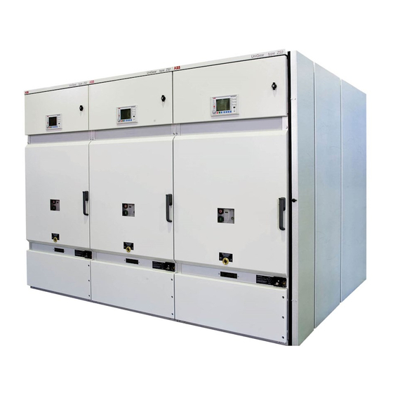
ABB UniGear ZS2 UniSafe 36 Installation And Maintenance Instructions Manual
Mv arc-proof air insulated metal-clad switchboards
Hide thumbs
Also See for UniGear ZS2 UniSafe 36:
Table of Contents
Advertisement
Quick Links
UniGear type ZS2
Installation and maintenance instructions for
MV arc-proof air insulated metal-clad switchboards
This Manual contains general information needed for receiving, installation, commissioning,
operation and maintainence of the switchboards.
The trade name of switchboards are referred as UniGear type ZS2 after june2004
UniSafe 36
Advertisement
Table of Contents

Related Manuals for ABB UniGear ZS2 UniSafe 36


Summary of Contents for ABB UniGear ZS2 UniSafe 36
- Page 1 UniGear type ZS2 UniSafe 36 Installation and maintenance instructions for MV arc-proof air insulated metal-clad switchboards This Manual contains general information needed for receiving, installation, commissioning, operation and maintainence of the switchboards. The trade name of switchboards are referred as UniGear type ZS2 after june2004...
-
Page 2: Table Of Contents
CONTENTS INTRODUCTION ................................3 PRODUCT DESCRIPTION ............................4 Ratings...................................4 Typical sections..............................4 1200mm width version ............................5 INSTALLATION INSTRUCTION ..........................6 Floor ..................................6 Space requirement ..............................8 Unpacking and transport ............................9 Cubicle’s erection..............................10 Busbar assembly..............................11 Through Earth Bar...............................15 Cables termination...............................16 Final Tightening ..............................17 Control Cables..............................17 2.10 End covers................................18... -
Page 3: Introduction
On receipt the switchgear must be unpacked and checked. Damages from transportation or other irregularities must be notified and reported to the related ABB office. Identity No. and ratings of switchgear can be seen on the rating plate on inner side of LVC. -
Page 4: Product Description
1 PRODUCT DESCRIPTION Ratings Rated values of Switchgear acc. to IEC 62271-200 appear on the nameplate which is inside the L.V. compartment door. The typical panels are Internal arc tested 25kA/1s, acc to IEC 60298 annex-AA, accessibility AF-LR, criteria 1...6. Rated values of apparatus (Circuit breaker, Earthing switch, CT, VT etc) appear on the respective component. -
Page 5: 1200Mm Width Version
Metering Circuit Breaker Feeder, 1600-2000-2500A Fig:1.2.5 Fig:1.2.6 Complementary pair Width: 2x1000mm (including metering) 1600-2000-2500A Sectionalizer 1600-2000-2500A Busriser Fig:1.2.7 Fig:1.2.8 1200mm width version C.B.Feeder 630-1250-1600-2000-2500A Fig:1.3.1 Installation and maintenance instructions UniGear type ZS2 UniSafe-36 1YTW571780-012 Rev:E 01-2005 en Page: 5 of 25... -
Page 6: Installation Instruction
2 INSTALLATION INSTRUCTION CAUTION! Make sure that the cubicle can not be dropped or tilted during unpacking, transportation or assembly. CAUTION! The encapsulating sheet steel of cubicles may have sharp edges inside and on the roof. Floor Check the floor regarding openings for the cables according to figure 2.1.1 and/or 2.1.2 Check the floor level. - Page 7 The cubicles can be installed on different types of floors. Anchoring bolts on Concrete flooring: Holes for the cables should be as small as possible. Avoid having single phase cables separated in different holes in such a way that magnetic heating occurs in the iron-reinforcement. After the cable termination the opening shall be sealed against fire and small animals.
-
Page 8: Space Requirement
Space requirement A typical installation in building is shown below. During order-bound design of substation the written dimensions as well as the min. dimensions should be considered. Fig: 2.2.1 sectional layout view, typical Front clearance 1500 mm (min) Ceiling height 3000 mm (min) see fig 2.1.1 Fig: 2.2.2 rear building view, typical dimensions indicate rectangular holes for arc duct channel... -
Page 9: Unpacking And Transport
Unpacking and transport The packing is intended for transport and not for storing purpose. Upon receipt the switchgear must be unpacked and installed under clean, dry, dust-free, indoor conditions and anti-condensation heaters should be connected. The cubicles which are without vacuum packing are normally fixed to the pallet. The palette is suitable for lifting by transpalette or fork-lift from all four sides provided that the width and length of transpalette is fitting. -
Page 10: Cubicle's Erection
The HD4 breakers are delivered either in the panels or in separate packing according to order planning. The HD4 breaker has the liftingspots marked and crane-lifting must consider these spots. Please refer to Instruction Manual for Fig:2.3.7 2.3.8 2.3.9 HD4W-36kV circuit breakers. Doc:ITNIE647016/003 Circuit Breaker Trolley, Fixed height. -
Page 11: Busbar Assembly
Make sure the contact surfaces of busbars and connector parts are clean. Use only the strong type of conical spring-washers (ABB 9ADA334, DIN 6796) for all bolted conductor connections. This will keep the required pressure for the lifetime of the switchgear eliminate the risk of problems due to overheating. - Page 12 Below are guide-figures for busbars assembly. Fig: 2.5.5 Fig: 2.5.4 Fig: 2.5.7 Fig:2.5.6 Fig:2.5.8 Fig:2.5.9 Main busbar 2500A, Circuit: 1600-2000-2500A 2500A Main busbars should be installed while panel erection. Otherwise access necessary both from the busbar compartment and the CB compartment. Installation and maintenance instructions UniGear type ZS2 UniSafe-36...
- Page 13 Fig:2.5.10 2500A Busbar connections with helicoil springs. Adjacent springs are in opposite direction. The connection helicoil springs are contact-greased against oxidation.At the end of installation rotate a few times the busbars for best connection surface. The tee connectors on the droppers are pre-assembled during production and normally need not to be dis- assembled.
- Page 14 Fig:2.5.17 Sectionalizer-Busriser lower main bars assembly, 1250A Fig:2.5.18 Sectionalizer-Busriser lower main bars assembly, 1600-2000-2500A Fig:2.5.21 Fig:2.5.19 Fig:2.5.20 View from front of lower main bars 1600-2000-2500A. Sectionalizer (left) Busriser (middle) Detail of fixing by 2 pcs M12 bolts (right) Installation and maintenance instructions UniGear type ZS2 UniSafe-36 1YTW571780-012 Rev:E 01-2005 en Page: 14 of 25...
-
Page 15: Through Earth Bar
All cubicles have a copper bar for the earth system. The main earth bar is placed at bottom of cubicle under the earthing switches. Those bars should be bolted together and the station earth system shall be connected to through earth bar. Conical washers to ABB standard 9ADA334 must also be used throughout the earth bar connections. -
Page 16: Cables Termination
Cables termination The cables must have been earthed before access to cables compartment. Removal of the horizontal bottom plate in the breaker compartment and/or removal of the rear-cover allows access to cables compartment. Please consider that some commissioning tests (part 3) are done with the power cables disconnected. Fig:2.7.1 Fig 2.7.2 Fig:2.7.3... -
Page 17: Final Tightening
1) Mark and prepare holes on the aluminium bottom plates 2) Pull the cable into the cable compartment and make a termination according to the suppliers instructions. 3) put a transparent hose onto the earthwire and connect it to the earth-bar. 4) Bring the cable to a final position and fix it with clamp such that connection points are not forced. -
Page 18: End Covers
3 PUTTING INTO SERVICE All operations for putting into service must be carried out either by ABB personnel or other skilled personnel authorized by the user organization. CAUTION! Untill putting into service by authorized and skilled personnel the switchgear must not be energized. -
Page 19: Operating Instruction
4 OPERATING INSTRUCTION The operators access area is in front of the switchgear. Only authorized operating personnel may access the switchgear. CAUTION! Only the Circuit breaker compartment door and Low Voltage compartment door can be necessary to open by operator. Do not attempt to open any other covers or shutters or screens before reading part 5 Maintenance instruction. - Page 20 Closing the earthing switch: Check that the circuit breaker is in test or withdrawn position. Open the lever entrance(11) by turning 90º the handle(10) anti-clockwise. This will not be possible if: -the CB is in service position -keylocked (7) for Esw at open position.. Do not force.
-
Page 21: Circuit Breaker, Hd-4 W 36
Circuit Breaker, HD-4 W 36 Please refer also to: Installation and service instructions, HD4 CHAPTER-6 ABB doc. no: ITNIE647016-003 Fig:4.2.1 Fig:4.2.2 Fig:4.2.3 CB in SERVICE (connected) CB in TEST (disconnected) CB WITHDRAWN (removed) RACKING HD4 BREAKER INTO SERVICE POSITION -1 Place the breaker onto the CB trolley. - Page 22 Fig:4.2.4 Fig:4.2.5 Handles for CB racking and Fig:4.2.6 Front panel of HD4 at test Handle for CB Springs manual charging Esw operation position of CB Fig:4.2.7 Fig:4.2.8 Fig:4.2.9 CB and VT racking handle Multi-pole auxiliary circuit plugged-in and Front panel of HD4 at test position of CB locked at service position of CB Fig:4.2.10 CB position limit switches inside the LV compartment * service (connected) ** test(disconnected) Installation and maintenance instructions...
-
Page 23: Withdrawable Voltage Transformer
Withdrawable Voltage Transformer CAUTION! For safety reasons VT-racking shall be done behind the closed door. CAUTION! The voltage transformers must not be accessable while they are in connected position. The compartment door of the voltage transformer should have caution label and locked by pad-lock so that only authorized maintenance personnel can open. -
Page 24: Maintenance Instruction
5 MAINTENANCE INSTRUCTION General All operations for maintenance must be carried out either by ABB personnel or other skilled personnel authorized by the user organization. CAUTION! To ensure safety during maintenance work, all parts of the main circuit to which access is required must be earthed prior to access. - Page 25 This manual is continously updated and we would appreciate user’s view regarding the contents of this manual. Please notify: ABB Elektrik Sanayi A.S. Organize Sanayi Bölgesi 2.Cadde No. 16 Yukari Dudullu 81260 Istanbul Turkey Tel: +90 216 5282200 Tfax: +90 216 3652943 e-mail: unisafe36.mail@tr.abb.com...