Table of Contents
Advertisement
Quick Links
SPECIFICATIONS
Product Name:
Product Series Name:
Product Model Number:
Motion Control Business Unit, Industrial Device Business Division
7-1-1 Morofuku,Daito-City,Osaka 574-0044,Japan
If you have any questions, please contact the seller (Sales office or Distributor) of the product.
SPECIFICATIONS
AC servo driver
MINAS-A6B series
DC24 / 48 V type
Panasonic Industry Co., Ltd.
Document No.
: SX-DSV03510
Revision No.
: 1.0
Date of Issue
: July.
Classification
:■ New □ Change
19, 2022
Advertisement
Table of Contents

Related Manuals for Panasonic MINAS-A6B Series


Summary of Contents for Panasonic MINAS-A6B Series
- Page 1 Product Series Name: Product Model Number: DC24 / 48 V type Motion Control Business Unit, Industrial Device Business Division Panasonic Industry Co., Ltd. 7-1-1 Morofuku,Daito-City,Osaka 574-0044,Japan If you have any questions, please contact the seller (Sales office or Distributor) of the product.
- Page 2 No. SX-DSV03510 REVISIONS Date Page Rev. Description Signed July. 19, 2022 Newly issued R1.0 Motion Control Business Unit, Panasonic Industry Co., Ltd.
-
Page 3: Table Of Contents
11-1 Expected life span of servo driver ........................37 12. Warranty ................................. 37 12-1 Warranty period .............................. 37 12-2 Warranty coverage ............................37 12-3 Warranty service ............................. 37 13. Network Security ..............................38 R1.0 Motion Control Business Unit, Panasonic Industry Co., Ltd. - Page 4 No. SX-DSV03510 14. Additional Precautions ............................39 15. Other notes of specification ............................ 40 16. Specifications for each model ..........................41 Appendix List of Default Parameters ..........................46 R1.0 Motion Control Business Unit, Panasonic Industry Co., Ltd.
-
Page 5: Scope Of Application
This specification relates to the MINAS A6B series of AC servo driver manufactured by the Motion Control Business Unit , Industrial Device Business Division, Panasonic Industry Co., Ltd. This product is intended for use as industrial equipment. It must not be used for any other purpose (e.g., for home use). -
Page 6: How To Read Product Numbers
L : A6 series B: EtherCAT Power supply voltage Safety function C: DC 24 V N: No safety function B: DC 48 V Output category Indicates the difference in applicable motors (or output ratings). R1.0 Motion Control Business Unit, Panasonic Industry Co., Ltd. -
Page 7: Product Line-Up
MVDLN3BBL 60540042 ― ― MVDLN4BBL 60540043 ― ― MVDLN5BBL 60540023 ― ― 30.5 (*Note 1) This is the Product code of our Servo Drive written in the ESI file (Hex numeral). R1.0 Motion Control Business Unit, Panasonic Industry Co., Ltd. -
Page 8: Specifications
When input power supply voltage is below the rated value (24 V/48 V), overload protection might be triggered even speed and torque are within the rated range at some motor's specifications. (Note 3) Please note that condensation tend to occur when temperature fall. R1.0 Motion Control Business Unit, Panasonic Industry Co., Ltd. -
Page 9: Basic Specifications Of Linear / Dd /Vcm Motor
When input power supply voltage is below the rated value (24 V/48 V), overload protection might be triggered even speed and torque are within the rated range at some motor's specifications. (Note 3) Please note that condensation tend to occur when temperature fall. R1.0 Motion Control Business Unit, Panasonic Industry Co., Ltd. -
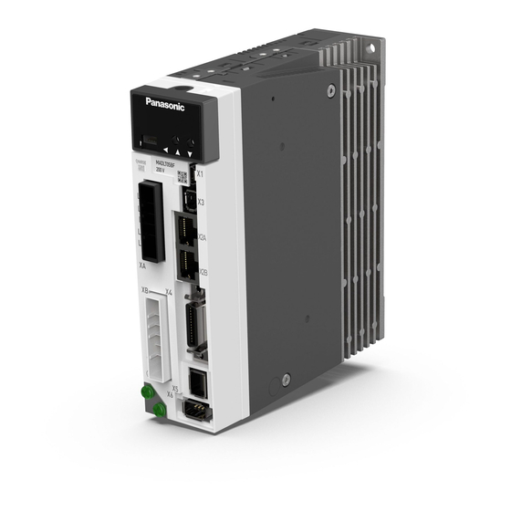
Page 10: Appearance And Name Of Each Part
No. SX-DSV03510 - 6 - 5. Appearance and name of each part Below figure shows linear / DD /VCM type. Rotary type is not provided with X5 (feedback scale connector). R1.0 Motion Control Business Unit, Panasonic Industry Co., Ltd. - Page 11 B000 - B999 17000 - 17999 H000 - H999 18000 - 18999 J000 - J999 22000 - 22999 N000 - N999 23000 - 23999 P000 - P999 33000 - 33999 Z000 - Z999 R1.0 Motion Control Business Unit, Panasonic Industry Co., Ltd.
- Page 12 LED status indicate status of network communication. For details of communication status, please refer to Technical Reference - EtherCAT Communication Specification -. L/A IN Link Activity IN LED Green L/A OUT Link Activity OUT LED Green R1.0 Motion Control Business Unit, Panasonic Industry Co., Ltd.
-
Page 13: Outside Dimensions
Below figure shows linear / DD /VCM type. Rotary type is not provided with X5 (feedback scale connector). Unit: mm * Do not use threaded screw holes that do not have description of dimensions. R1.0 Motion Control Business Unit, Panasonic Industry Co., Ltd. -
Page 14: Configuration Of Connectors And Terminal Blocks
• Connect U phase of the motor winding • Connect V phase of the motor winding • Connect W phase of the motor winding • Connect frame ground wire of the motor R1.0 Motion Control Business Unit, Panasonic Industry Co., Ltd. -
Page 15: Usb Connector X1
Frame ground Shell Connect to shield of cable. • Be sure to use shielded twisted pair (STP) compatible with 5e of TIA/EIA-568 or higher category Auto MDI/MDI-X assigns functions to pin no.1,2,3,6. R1.0 Motion Control Business Unit, Panasonic Industry Co., Ltd. -
Page 16: Parallel I/O Connector, X4
OB-/OCMP2- B-phase output / OB+/OCMP2+ Position compare output 2 OCMP3+ Position compare output 3 OCMP3- No use ― Signal ground SO2+ Control output 2 SO2- Signal ground Frame ground Pin layout R1.0 Motion Control Business Unit, Panasonic Industry Co., Ltd. - Page 17 For details, refer to “Technical reference - Basic Functional Specifications -”. SO2+ Control output 2 SO2- Output for alarm of servo driver. ALM+ Alarm output Normally: output transistor ON ALM- Alarm: output transistor OFF R1.0 Motion Control Business Unit, Panasonic Industry Co., Ltd.
- Page 18 Frame ground Internally connect to the case Signal ground Signal ground Internally connect to N-pin of power supply connector XA-1 and XA-2. Reserved Do not connect anything R1.0 Motion Control Business Unit, Panasonic Industry Co., Ltd.
-
Page 19: Feedback Scale Connector X5
Count-down direction Count-up direction EXB is advanced 90° than EXA EXB is retarded 90° than EXA t1 > 0.25 µs t1 > 0.25 µs t2 > 1.0 µs t2 > 1.0 µs R1.0 Motion Control Business Unit, Panasonic Industry Co., Ltd. -
Page 20: Encoder / Cs Signal Connector X6
CS 1 advances 120 ° from CS 2 CS 3 advances 120 ° from CS 2 CS 2 advances 120 ° from CS 3 CS 2 advances 120 ° from CS 1 R1.0 Motion Control Business Unit, Panasonic Industry Co., Ltd. -
Page 21: Input / Output Signal Interface
+: 17, 20, 21 -: 18, 19, 22 Pins: Note) Connect a terminating resistor (approx. 330 Ω) S:(X6) 1, 2, 3 between the input terminals of the line receiver. G:(X6) 5 R1.0 Motion Control Business Unit, Panasonic Industry Co., Ltd. -
Page 22: Wiring And System Configuration
Encoder / CS signal connection (Note 1) The above wiring length is the maximum value under the evaluation environment of Panasonic. It does not guarantee the operation under the working environment of the customer. The above wiring length is the maximum wiring length including tolerance of processing. -
Page 23: Precautions For Wiring
Below figure do not shows all pins of each connector. Servo driver XA-1 Main Power Supply DC24 V / 48 V XA-2 Control Power Supply DC24 V / 48 V Green White Black X2A/X2B shell EX0V shell Frame R1.0 Motion Control Business Unit, Panasonic Industry Co., Ltd. - Page 24 When using an earth leakage breaker, take measures against high frequency. [8] Brake power supply for the motor with brake should be prepared by customer. [9] Apply power supply voltage after completing wiring. R1.0 Motion Control Business Unit, Panasonic Industry Co., Ltd.
-
Page 25: Wiring To Connectors X2A And X2B
Blue White/Brown Brown Shield on connector Shield on connector Higher-level device or servo driver in the Servo driver Shielded twisted pair cable of 5e or higher category preceding circuit MAX:50 m R1.0 Motion Control Business Unit, Panasonic Industry Co., Ltd. -
Page 26: Wiring To Connector X4
4.7 kΩ 4.7 kΩ 4.7 kΩ 4.7 kΩ Servo driver The functions of pins SI1 – SI8 should be allocated by parameters. For details, refer to “Technical Reference - Functional Specifications -”. R1.0 Motion Control Business Unit, Panasonic Industry Co., Ltd. - Page 27 DC12 - 24 V ALM+ 10 Ω ALM- Servo driver The functions of pins SO1, SO2 should be allocated by parameters. For details, refer to “Technical Reference - Functional Specifications -”. R1.0 Motion Control Business Unit, Panasonic Industry Co., Ltd.
-
Page 28: Wiring To Connector X5
[8] When driving a feedback scale using external power supply, make the EX5V pin open so that voltage is not supplied to this pin from outside. In addition, connect 0 V (GND) of the external power supply with EX0V (X5 2pin) of the driver to obtain the same electric potential. R1.0 Motion Control Business Unit, Panasonic Industry Co., Ltd. - Page 29 Servo driver Scale Cable Feedback scale unit Wiring example of the serial communication type EX5V EX0V EXPS EXPS (Serial signal) (Serial signal) Detection head Servo driver Feedback scale unit Scale Cable R1.0 Motion Control Business Unit, Panasonic Industry Co., Ltd.
-
Page 30: Wiring To Connector X6
[5] Do not connect nothing to pin 1. Twisted pair +5 V BAT+ Battery (*) BAT- 172169-1 (Tyco electronics) Motor Encoder cable Servo driver (*) When not use absolute system, remove battery. R1.0 Motion Control Business Unit, Panasonic Industry Co., Ltd. - Page 31 If you use battery unit DV0P2990 (built-in battery: ER6V 3.6V made by TOSHIBA LIFESTYLE PRODUCTS & SERVICES), which is an optional item of Panasonic, connect the connector with lead wire to CN601 as shown in the right figure and set it aside for five minutes.
- Page 32 [10] Wiring of X6 is unnecessary when magnetic pole position estimation function is used without using CS signal. EX5V EX0V CS-GND Detection head Servo driver Scale Cable Feedback scale unit R1.0 Motion Control Business Unit, Panasonic Industry Co., Ltd.
-
Page 33: Dynamic Brake
• As shown below, install the servo amplifier so that the connector XA - 1 faces downward. When other installation directions, use at ambient temperature of 45 ° C or less. R1.0 Motion Control Business Unit, Panasonic Industry Co., Ltd. -
Page 34: Compliance With The International Standards
To comply with the EMC directive, use a noise filter, a surge absorber, and a ferrite core. The compliance of machinery and equipment with the EMC Directive must be confirmed on machinery and equipment in its final state incorporating servo drivers and servo motors. R1.0 Motion Control Business Unit, Panasonic Industry Co., Ltd. -
Page 35: Configuration Of Peripheral Devices
When performing a withstand test for the machines and devices, be sure to remove the surge absorber. Otherwise, the surge absorber may get damaged. 9-3-5 Ferrite core Install the ferrite cores for signal lines in all cables (power supply, motor, encoder, and interface cables). R1.0 Motion Control Business Unit, Panasonic Industry Co., Ltd. -
Page 36: List Of Servo Drivers And Applicable Peripheral Devices
This product is an electromagnetic wave generating device for business use (Class A), which is intended for the use in places other than household. The distributor and the user should be attentive to this point. (Applicable model: Servo Driver) R1.0 Motion Control Business Unit, Panasonic Industry Co., Ltd. -
Page 37: Safety Precautions
(14) Wiring work should be carried out by an electrical engineer. (15) Motors other than that specified do not include protective devices. Protect them using overcurrent protection devices, ground-fault circuit interrupters, overheating prevention devices, emergency stop devices, etc. R1.0 Motion Control Business Unit, Panasonic Industry Co., Ltd. - Page 38 (34) If the motor has a built-in brake, it is for maintenance purposes and should not be used as a stopping (braking) device in order to ensure machine safety. (35) Do not drop or tip over the product during transportation or installation. R1.0 Motion Control Business Unit, Panasonic Industry Co., Ltd.
- Page 39 (38) Do not expose the product to direct sunlight. When storing the product, keep it away direct sunlight and store at temperatures and humidity within the specified ranges. (39) Do not attempt to overhaul or modify the motor. Overhauls must be carried out by Panasonic or an authorized dealer.
- Page 40 If the temperature cannot be measured from a distance of 50 mm, measure at the midpoint of the gap between the obstacle preventing measurement and the servo driver. Operating temperature range: 0 - 55°C R1.0 Motion Control Business Unit, Panasonic Industry Co., Ltd.
-
Page 41: Life Span
As a general rule, you will be responsible for shipping costs. R1.0 Motion Control Business Unit, Panasonic Industry Co., Ltd. -
Page 42: Network Security
・If the product is to be disposed of, transferred, repaired, or otherwise transferred to a third party, important information may also be recorded on the product. At customer's risk, please handle it with care, such as erasing it. R1.0 Motion Control Business Unit, Panasonic Industry Co., Ltd. -
Page 43: Additional Precautions
(19) Do not reverse engineer, decompile, or disassemble this product. (20) Abnormal current may cause thermal damage with some linear motors. (21) Ensure safety against thermal damage on the equipment by covering the linear motor with nonflammable materials, etc. R1.0 Motion Control Business Unit, Panasonic Industry Co., Ltd. -
Page 44: Other Notes Of Specification
No. SX-DSV03510 - 40 - 15. Other notes of specification ・Main power supply and the control circuit are not isolated. Please Insulate processing if necessary R1.0 Motion Control Business Unit, Panasonic Industry Co., Ltd. -
Page 45: Specifications For Each Model
Not supported. Weight Approx 0.35 kg Approx 0.35 kg Approx 0.35 kg Approx 0.35 kg Dimensions 89×180×30 mm 89×180×30 mm 89×180×30 mm 89×180×30 mm (Note 1) Rated capacitance specified by parts manufacturer R1.0 Motion Control Business Unit, Panasonic Industry Co., Ltd. - Page 46 Not supported. Weight Approx 0.35 kg Approx 0.35 kg Approx 0.35 kg Approx 0.35 kg Dimensions 89×180×30 mm 89×180×30 mm 89×180×30 mm 89×180×30 mm (Note 1) Rated capacitance specified by parts manufacturer R1.0 Motion Control Business Unit, Panasonic Industry Co., Ltd.
- Page 47 No limit by driver No limit by driver Regenerative discharge Not supported. Not supported. Weight Approx 0.35 kg Approx 0.35 kg Dimensions 89×180×30 mm 89×180×30 mm (Note 1) Rated capacitance specified by parts manufacturer R1.0 Motion Control Business Unit, Panasonic Industry Co., Ltd.
- Page 48 Not supported. Weight Approx 0.35 kg Approx 0.35 kg Approx 0.35 kg Approx 0.35 kg Dimensions 89×180×30 mm 89×180×30 mm 89×180×30 mm 89×180×30 mm (Note 1) Rated capacitance specified by parts manufacturer R1.0 Motion Control Business Unit, Panasonic Industry Co., Ltd.
- Page 49 No limit by driver No limit by driver Regenerative discharge Not supported. Not supported. Weight Approx 0.35 kg Approx 0.35 kg Dimensions 89×180×30 mm 89×180×30 mm (Note 1) Rated capacitance specified by parts manufacturer R1.0 Motion Control Business Unit, Panasonic Industry Co., Ltd.
-
Page 50: Appendix List Of Default Parameters
The following pages show default parameters set when the servo driver is shipped from the factory. Operation must be confirmed for each customer machine before use and the optimal parameters set. R1.0 Motion Control Business Unit, Panasonic Industry Co., Ltd. - Page 51 ■Default value of the parameters(1/11) No.SX-DSV03510 Appendix1 PARAMETER MODEL MINAS-A6BE SizeV series Default Default Default Default Default Cate Cate Cate Cate Cate Parameter Parameter Parameter Parameter Parameter gory value gory value gory value gory value gory value 0 For Manufacturer's use 1 Control mode setup Real-time auto-gain tuning setup Selection of machine stiffness at real-...
- Page 52 ■Default value of the parameters(2/11) No.SX-DSV03510 Appendix1 PARAMETER MODEL MINAS-A6BE SizeV series Default Default Default Default Default Cate Cate Cate Cate Cate Parameter Parameter Parameter Parameter Parameter gory value gory value gory value gory value gory value 1st gain of position loop 48.0 31 For Manufacturer's use 62 For Manufacturer's use...
- Page 53 ■Default value of the parameters(3/11) No.SX-DSV03510 Appendix1 PARAMETER MODEL MINAS-A6BE SizeV series Default Default Default Default Default Cate Cate Cate Cate Cate Parameter Parameter Parameter Parameter Parameter gory value gory value gory value gory value gory value 0 Adaptive filter mode setup 31 For Manufacturer's use 1 1st notch frequency 5000...
- Page 54 ■Default value of the parameters(4/11) No.SX-DSV03510 Appendix1 PARAMETER MODEL MINAS-A6BE SizeV series Default Default Default Default Default Cate Cate Cate Cate Cate Parameter Parameter Parameter Parameter Parameter gory value gory value gory value gory value gory value 0 No use 31 No use 1 No use 32 No use...
- Page 55 ■Default value of the parameters(5/11) No.SX-DSV03510 Appendix1 PARAMETER MODEL MINAS-A6BE SizeV series Default Default Default Default Default Cate Cate Cate Cate Cate Parameter Parameter Parameter Parameter Parameter gory value gory value gory value gory value gory value Positioning complete (In-position) 0 SI1 input selection 3289650 8400...
- Page 56 ■Default value of the parameters(6/11) No.SX-DSV03510 Appendix1 PARAMETER MODEL MINAS-A6BE SizeV series Default Default Default Default Default Cate Cate Cate Cate Cate Parameter Parameter Parameter Parameter Parameter gory value gory value gory value gory value gory value 0 No use 31 USB axis address 62 No use 93 No use...
- Page 57 ■Default value of the parameters(7/11) No.SX-DSV03510 Appendix1 PARAMETER MODEL MINAS-A6BE SizeV series Default Default Default Default Default Cate Cate Cate Cate Cate Parameter Parameter Parameter Parameter Parameter gory value gory value gory value gory value gory value Real time auto tuning estimation 0 No use 62 1st resonance attenuation ratio 93 No use...
- Page 58 ■Default value of the parameters(8/11) No.SX-DSV03510 Appendix1 PARAMETER MODEL MINAS-A6BE SizeV series Default Default Default Default Default Cate Cate Cate Cate Cate Parameter Parameter Parameter Parameter Parameter gory value gory value gory value gory value gory value 0 Display on LED 31 No use 62 No use Home position return limit speed...
- Page 59 ■Default value of the parameters(9/11) No.SX-DSV03510 Appendix1 PARAMETER MODEL MINAS-A6BE SizeV series Default Default Default Default Default Cate Cate Cate Cate Cate Parameter Parameter Parameter Parameter Parameter gory value gory value gory value gory value gory value 0 For Manufacturer's use Profile linear acceleration constant 2 For Manufacturer's use 3 For Manufacturer's use...
- Page 60 ■Default value of the parameters(10/11) No.SX-DSV03510 Appendix1 PARAMETER MODEL MINAS-A6BE SizeV series Default Default Default Default Default Cate Cate Cate Cate Cate Parameter Parameter Parameter Parameter Parameter gory value gory value gory value gory value gory value 0 For Manufacturer's use 31 For Manufacturer's use External scale resolution 32 For Manufacturer's use...
- Page 61 ■Default value of the parameters(11/11) No.SX-DSV03510 Appendix1 PARAMETER MODEL MINAS-A6BE SizeV series Default Default Default Default Default Cate Cate Cate Cate Cate Parameter Parameter Parameter Parameter Parameter gory value gory value gory value gory value gory value 0 For Manufacturer's use 15 31 For Manufacturer's use 1 No use 32 No use...
- Page 62 ■Default value of the parameters(1/11) No.SX-DSV03510 Appendix2 PARAMETER MODEL MINAS-A6BL SizeV series Default Default Default Default Default Categ Categ Categ Categ Categ Parameter Parameter Parameter Parameter Parameter value value value value value 0 For manufacturer's use 1 For manufacturer's use Real-time auto-gain tuning setup Selection of machine stiffness at real- time auto-gain tuning...
- Page 63 ■Default value of the parameters(2/11) No.SX-DSV03510 Appendix2 PARAMETER MODEL MINAS-A6BL SizeV series Default Default Default Default Default Categ Categ Categ Categ Categ Parameter Parameter Parameter Parameter Parameter value value value value value 1st gain of position loop 48.0 31 For manufacturer's use 62 For manufacturer's use 1st gain of velocity loop 27.0...
- Page 64 ■Default value of the parameters(3/11) No.SX-DSV03510 Appendix2 PARAMETER MODEL MINAS-A6BL SizeV series Default Default Default Default Default Categ Categ Categ Categ Categ Parameter Parameter Parameter Parameter Parameter value value value value value 0 Adaptive filter mode setup 31 For manufacturer's use 1 1st notch frequency 32 For manufacturer's use 5000...
- Page 65 ■Default value of the parameters(4/11) No.SX-DSV03510 Appendix2 PARAMETER MODEL MINAS-A6BL SizeV series Default Default Default Default Default Categ Categ Categ Categ Categ Parameter Parameter Parameter Parameter Parameter value value value value value 0 No use 31 No use 1 No use 32 No use 2 No use 33 For manufacturer's use...
- Page 66 ■Default value of the parameters(5/11) No.SX-DSV03510 Appendix2 PARAMETER MODEL MINAS-A6BL SizeV series Default Default Default Default Default Categ Categ Categ Categ Categ Parameter Parameter Parameter Parameter Parameter value value value value value Positioning complete (In-position) 0 SI1 input selection 3289650 range Positioning complete (In-position) 1 SI2 input selection...
- Page 67 ■Default value of the parameters(6/11) No.SX-DSV03510 Appendix2 PARAMETER MODEL MINAS-A6BL SizeV series Default Default Default Default Default Categ Categ Categ Categ Categ Parameter Parameter Parameter Parameter Parameter value value value value value 0 No use 31 USB axis address 62 No use 93 No use 1 No use 32 No use...
- Page 68 ■Default value of the parameters(7/11) No.SX-DSV03510 Appendix2 PARAMETER MODEL MINAS-A6BL SizeV series Default Default Default Default Default Categ Categ Categ Categ Categ Parameter Parameter Parameter Parameter Parameter value value value value value Real time auto tuning estimation 0 No use 1st resonance attenuation ratio 93 No use speed...
- Page 69 ■Default value of the parameters(8/11) No.SX-DSV03510 Appendix2 PARAMETER MODEL MINAS-A6BL SizeV series Default Default Default Default Default Categ Categ Categ Categ Categ Parameter Parameter Parameter Parameter Parameter value value value value value 0 Display on LED 31 No use 62 No use Home position return limit speed 32 No use 63 No use...
- Page 70 ■Default value of the parameters(9/11) No.SX-DSV03510 Appendix2 PARAMETER MODEL MINAS-A6BL SizeV series Default Default Default Default Default Categ Categ Categ Categ Categ Parameter Parameter Parameter Parameter Parameter value value value value value 0 For manufacturer's use Profile linear acceleration constant 2 For manufacturer's use 3 For manufacturer's use Profile linear deceleration...
- Page 71 ■Default value of the parameters(10/11) No.SX-DSV03510 Appendix2 PARAMETER MODEL MINAS-A6BL SizeV series Default Default Default Default Default Categ Categ Categ Categ Categ Parameter Parameter Parameter Parameter Parameter value value value value value 0 Motor type selection 31 For manufacturer's use Feedback scale resolution/ 32 For manufacturer's use Number of scale pulses per rotation...
- Page 72 ■Default value of the parameters(11/11) No.SX-DSV03510 Appendix2 PARAMETER MODEL MINAS-A6BL SizeV series Default Default Default Default Default Categ Categ Categ Categ Categ Parameter Parameter Parameter Parameter Parameter value value value value value 0 For manufacturer's use 31 For manufacturer's use 1 No use 32 No use 2 For manufacturer's use...
- Page 73 No.SX-DSV03510 Appendix3 (1/19) ■EtherCAT Object Initial value ◎ CoE communication profile area (1000h~1FFFh) Initial value Index Sub-Index Name Read Only 1000h Device type Read Only 1001h Error register Read Only 1008h Manufacturer device name Read Only 1009h Manufacturer hardware version Read Only 100Ah Manufacturer software version -...
- Page 74 No.SX-DSV03510 Appendix3 (2/19) ■EtherCAT Object Initial value ◎ CoE communication profile area (1000h~1FFFh) Initial value Index Sub-Index Name - Receive PDO mapping 1 Number of entries 1614807056 1st receive PDO mapped 1616904200 2nd receive PDO mapped 1618608160 3rd receive PDO mapped 1622671376 4th receive PDO mapped 5th receive PDO mapped 6th receive PDO mapped...
- Page 75 No.SX-DSV03510 Appendix3 (3/19) ■EtherCAT Object Initial value ◎ CoE communication profile area (1000h~1FFFh) Initial value Index Sub-Index Name - Receive PDO mapping 2 Number of entries 1614807056 1st receive PDO mapped 1616904200 2nd receive PDO mapped 1618018320 3rd receive PDO mapped 1618608160 4th receive PDO mapped 1619001376 5th receive PDO mapped...
- Page 76 No.SX-DSV03510 Appendix3 (4/19) ■EtherCAT Object Initial value ◎ CoE communication profile area (1000h~1FFFh) Initial value Index Sub-Index Name - Receive PDO mapping 3 Number of entries 1614807056 1st receive PDO mapped 1616904200 2nd receive PDO mapped 1618083856 3rd receive PDO mapped 1618608160 4th receive PDO mapped 1622671376 5th receive PDO mapped...
- Page 77 No.SX-DSV03510 Appendix3 (5/19) ■EtherCAT Object Initial value ◎ CoE communication profile area (1000h~1FFFh) Initial value Index Sub-Index Name - Receive PDO mapping 4 Number of entries 1614807056 1st receive PDO mapped 1616904200 2nd receive PDO mapped 1618018320 3rd receive PDO mapped 1618083856 4th receive PDO mapped 1618608160 5th receive PDO mapped...
- Page 78 No.SX-DSV03510 Appendix3 (6/19) ■EtherCAT Object Initial value ◎ CoE communication profile area (1000h~1FFFh) Initial value Index Sub-Index Name - Transmit PDO mapping 1 Number of entries 1614741520 1st transmit PDO mapped 1614872592 2nd transmit PDO mapped 1616969736 3rd transmit PDO mapped 1617166368 4th transmit PDO mapped 1622736912 5th transmit PDO mapped...
- Page 79 No.SX-DSV03510 Appendix3 (7/19) ■EtherCAT Object Initial value ◎ CoE communication profile area (1000h~1FFFh) Initial value Index Sub-Index Name - Transmit PDO mapping 2 Number of entries 1614741520 1st transmit PDO mapped 1614872592 2nd transmit PDO mapped 1616969736 3rd transmit PDO mapped 1617166368 4th transmit PDO mapped 1617690656 5th transmit PDO mapped...
- Page 80 No.SX-DSV03510 Appendix3 (8/19) ■EtherCAT Object Initial value ◎ CoE communication profile area (1000h~1FFFh) Initial value Index Sub-Index Name - Transmit PDO mapping 3 Number of entries 1614741520 1st transmit PDO mapped 1614872592 2nd transmit PDO mapped 1616969736 3rd transmit PDO mapped 1617166368 4th transmit PDO mapped 1617690656 5th transmit PDO mapped...
- Page 81 No.SX-DSV03510 Appendix3 (9/19) ■EtherCAT Object Initial value ◎ CoE communication profile area (1000h~1FFFh) Initial value Index Sub-Index Name - Transmit PDO mapping 4 Number of entries 1614741520 1st transmit PDO mapped 1614872592 2nd transmit PDO mapped 1616969736 3rd transmit PDO mapped 1617166368 4th transmit PDO mapped 1617690656 5th transmit PDO mapped...
- Page 82 No.SX-DSV03510 Appendix3 (10/19) ■EtherCAT Object Initial value ◎ CoE communication profile area (1000h~1FFFh) Initial value Index Sub-Index Name - Sync manager 2 synchronization Read Only Number of sub-objects Sync mode 1000000 Cycle time Read Only Shift time Read Only Sync modes supported Read Only Minimum cycle time Read Only...
- Page 83 No.SX-DSV03510 Appendix3 (11/19) ■EtherCAT Object Initial value ◎ User-specific area (4000h~4FFFh) Initial value Index Sub-Index Name 4304h Touch probe function expansion setup 4308h History number 4310h Alarm main no - 4311h For manufacturer's use 5000 4312h Velocity control loop torque limit 4314h Analog input internal offset 4315h Analog deviation limit...
- Page 84 No.SX-DSV03510 Appendix3 (12/19) ■EtherCAT Object Initial value ◎ User-specific area (4000h~4FFFh) Initial value Index Sub-Index Name - Position comparison range Read Only Highest sub-index supported 4D57h Read Only Min position comparison range Read Only Max position comparison range - Alarm accessory information Read Only Number of entries Read Only...
- Page 85 No.SX-DSV03510 Appendix3 (13/19) ■EtherCAT Object Initial value ◎ User-specific area (4000h~4FFFh) Initial value Index Sub-Index Name Read Only 4F01h Following error actual value (after filtering) Read Only 4F03h Analog input internal voltage Read Only 4F04h Position command internal value (after filtering) - 4F0Bh For manufacturer's use Read Only...
- Page 86 No.SX-DSV03510 Appendix3 (14/19) ■EtherCAT Object Initial value ◎ User-specific area (4000h~4FFFh) Initial value Index Sub-Index Name - 4F53h For manufacturer's use Read Only 4F61h Power on cumulative time Read Only 4F62h Temperature of amplifier Read Only 4F63h Temperature of encoder Read Only 4F64h Inrush resistance relay operating count Read Only...
- Page 87 No.SX-DSV03510 Appendix3 (15/19) ■EtherCAT Object Initial value ◎ User-specific area (4000h~4FFFh) Initial value Index Sub-Index Name - 4FF6h For manufacturer's use - For manufacturer's use Read Only Number of entries 4FF7h - For manufacturer's use - For manufacturer's use - For manufacturer's use Read Only Number of entries 4FF8h...
- Page 88 No.SX-DSV03510 Appendix3 (16/19) ■EtherCAT Object Initial value ◎ Drive profile area (5000h~5FFFh) Initial value Index Sub-Index Name 5350h Homing torque limit value 5351h Homing detection time 5352h Homing detection velocity value...
- Page 89 No.SX-DSV03510 Appendix3 (17/19) ■EtherCAT Object Initial value ◎ Drive profile area (6000h~6FFFh) Initial value Index Sub-Index Name 6007h Abort connection option code Read Only 603Fh Error code 6040h Controlword Read Only 6041h Statusword 605Ah Quick stop option code 605Bh Shutdown option code 605Ch Disable operation option code 605Dh...
- Page 90 No.SX-DSV03510 Appendix3 (18/19) ■EtherCAT Object Initial value ◎ Drive profile area (6000h~6FFFh) Initial value Index Sub-Index Name 1000 6087h Torque slope 6088h Torque profile type - Position encoder resolution Read Only Highest sub-index supported 608Fh Read Only Encoder increments Read Only Motor revolutions -...
- Page 91 No.SX-DSV03510 Appendix3 (19/19) ■EtherCAT Object Initial value ◎ Drive profile area (6000h~6FFFh) Initial value Index Sub-Index Name - Supported homing method Read Only Number of entries Read Only 1st supported homing method Read Only 2nd supported homing method Read Only 3rd supported homing method Read Only 4th supported homing method Read Only...