Table of Contents
Advertisement
Quick Links
Comfort Panels INOX, ITC INOX
SIMATIC
HMI devices
Comfort Panels INOX, ITC INOX
Compact Operating Instructions
08/2022
A5E33472156-AP
Preface
Overview
Safety instructions
Installing and connecting
the device
Cleaning the device
Technical specifications
Technical Support
List of abbreviations
1
2
3
4
5
A
B
Advertisement
Table of Contents

Related Manuals for Siemens SIMATIC INOX


Summary of Contents for Siemens SIMATIC INOX
- Page 1 Comfort Panels INOX, ITC INOX Preface Overview SIMATIC Safety instructions Installing and connecting the device HMI devices Comfort Panels INOX, ITC INOX Cleaning the device Technical specifications Compact Operating Instructions Technical Support List of abbreviations 08/2022 A5E33472156-AP...
- Page 2 Note the following: WARNING Siemens products may only be used for the applications described in the catalog and in the relevant technical documentation. If products and components from other manufacturers are used, these must be recommended or approved by Siemens. Proper transport, storage, installation, assembly, commissioning, operation and maintenance are required to ensure that the products operate safely and without any problems.
-
Page 3: Preface
The notes in these compact operating instructions take precedence over statements in the basic operating instructions, the release notes and online help. Comfort Panels operating instructions (http://support.automation.siemens.com/WW/view/en/49313233) Industrial Thin Clients operating instructions (http://support.automation.siemens.com/WW/view/en/61187980) Unless otherwise described in this document, all of the statements made in the general operating manual concerning the basic device are valid for the corresponding INOX device. - Page 4 Preface Style conventions Style Convention Scope "Add screen" • Terms that occur in the user interface, for example, dialog name, tab, button, menu command • Necessary entries, for example, limit value, tag value • Path specification "File > Edit" Operating sequences, for example, menu item, shortcut menu command <F1>, <Alt+P>...
-
Page 5: Table Of Contents
Table of contents Preface ..............................3 Overview ..............................7 Product overview ......................... 7 Scope of delivery ......................... 8 Layout of the devices ......................8 Interfaces ..........................9 Accessories ........................10 Safety instructions ..........................11 General safety instructions ....................11 Notes on use ........................12 Supplemental notes ...................... - Page 6 Table of contents Dimension drawings ......................34 5.4.1 Dimension drawing TP700 Comfort INOX ................34 5.4.2 Dimension drawing TP900 Comfort INOX ................35 5.4.3 Dimension drawing TP1200 Comfort INOX ................. 36 5.4.4 Dimension drawing TP1200 Comfort INOX LF ..............37 5.4.5 Dimension drawing TP1500 Comfort INOX .................
-
Page 7: Overview
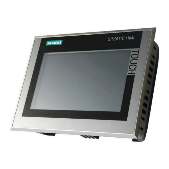
Overview Product overview INOX devices with touch screen and stainless steel front are designed for use in the food and beverage industry, including in splash zones of food production, the pharmaceutical industry, fine chemicals and in other hygiene areas for machine-level operator control and monitoring. For this reason, the devices with stainless steel front have been developed in compliance with DIN EN 1672-2 "Food processing machinery –... -
Page 8: Scope Of Delivery
Overview 1.2 Scope of delivery Scope of delivery Depending on the order, the scope of delivery includes: • 1 × device • 1 × accessory pack with the following contents: – 1 mounting gasket – 1 clamping frame – 1 power supply terminal –... -
Page 9: Interfaces
Overview 1.4 Interfaces Bottom view ① Ports ② Cutout for mounting clip Interfaces Interfaces for the 7", 9" and 12" HMI devices The figure below shows the interfaces for the following HMI devices: • TP700 Comfort INOX • TP900 Comfort INOX •... -
Page 10: Accessories
HMI device. Accessories Accessories can be ordered on the Internet at: Industry Mall (https://mall.industry.siemens.com) The following service packs with clamping frames, mounting gaskets, mounting clips and strain relief plate are available for the INOX devices: •... -
Page 11: Safety Instructions
Safety instructions General safety instructions Installation according to the instructions WARNING The device may only be used in machines which comply with the Machinery Directive The "Machinery Directive" governs, among other things, the precautions to be taken when commissioning and operating machines within the European Economic Area. Failure to follow these precautions is a breach of the Machinery Directive. -
Page 12: Notes On Use
Safety instructions 2.2 Notes on use Electrostatically sensitive components include almost all electrical, electronic, optoelectronic and electromechanical components. These components are sensitive to overvoltage for technical reasons and their function may be impaired or destroyed by electrostatic discharge. Observe the regulations governing the handling of ESD components. Notes on use Note Avoid direct or indirect contact with food in the area of the device's decorative foil to avoid... -
Page 13: Installing And Connecting The Device
Damaged parts A damaged part can cause device malfunctions. Do not install damaged parts. In the case of damaged parts or incomplete delivery, contact your Siemens representative. 3.2.2 Checking the operating conditions Note the following aspects before installing the device: 1. -
Page 14: Selecting A Mounting Position
Installing and connecting the device 3.2 Preparing for installation 3.2.3 Selecting a mounting position The HMI device is suitable for installation in: • Mounting cabinets • Control cabinets • Switchboards • Consoles In the following, all of these mounting options are referred to by the general term "cabinet". The HMI device is self-ventilated and approved for inclined mounting at angles of up to +/-35°... - Page 15 Installing and connecting the device 3.2 Preparing for installation Mounting position Select one of the approved mounting positions for your HMI device. The approved mounting positions are described in the following sections using the TP700 Comfort INOX as an example. Landscape mounting All HMI devices are suitable for landscape mounting.
-
Page 16: Checking Clearances
Installing and connecting the device 3.2 Preparing for installation 3.2.4 Checking clearances The following clearances are required around the HMI device to ensure sufficient self- ventilation: • At least 23 mm to the right and to the left of the mounting cutout (in the x direction) for mounting the clamping frame during installation •... -
Page 17: Inserting The Mounting Seal
Installing and connecting the device 3.3 Inserting the mounting seal Inserting the mounting seal The following figures in this section are examples. To prevent the mounting seal from being inserted in the wrong direction, it has an asymmetric coding tap. On all mounting gaskets of the INOX devices, the coding tap is on the bottom left in relation to the rear of the device. - Page 18 Installing and connecting the device 3.3 Inserting the mounting seal 2. Carefully place the device on the front of the device (interfaces point to you). 3. Insert the mounting seal into the stainless steel front as shown. Also note points ④ - ⑥. ④...
-
Page 19: Positions Of The Mounting Clips For Tp1900 Comfort Inox And Itc1900 Inox
Installing and connecting the device 3.4 Positions of the mounting clips for TP1900 Comfort INOX and ITC1900 INOX Positions of the mounting clips for TP1900 Comfort INOX and ITC1900 INOX The following section describes how you can install the device. Observe the following mounting clip positions for the TP1900 Comfort INOX and the ITC1900 INOX: Mounting the device The following process describes installation for all devices based on the example of the... - Page 20 Installing and connecting the device 3.5 Mounting the device Mounting CAUTION Risk of injury when device falls An unsecured device may fall. This can result in damage to persons, machines and the device. Secure the device against dropping during the entire installation. 1.
-
Page 21: Connecting The Device
Installing and connecting the device 3.6 Connecting the device 5. Check that the stainless steel front is in contact with the mounting location on all sides and that the mounting seal is pressed against the surrounding area. 6. Check that the fixed stop has been reached on all mounting clips and that the mounting gasket is installed correctly. -
Page 22: Securing Cables For Use In Hazardous Areas
Installing and connecting the device 3.7 Securing cables for use in hazardous areas Securing cables for use in hazardous areas When devices with Ex approval are used in hazardous areas, note that the connectors must be secured in a captive manner at the interfaces. WARNING Explosion hazard from sparks when connectors come loose If a plug connector comes loose from the associated device interface during operation in a... -
Page 23: Cleaning The Device
Cleaning the device Cleaning product The specifications in the operating instructions apply when using the device in hazardous areas of Zones 2 and 22. For use of the device at normal atmospheric conditions, the following is permitted in addition to the operating instructions: •... -
Page 24: Chemical Resistance
• Ester • Hydrocarbons • Household cleaners You can find information of chemical resistance on the Internet (https://support.industry.siemens.com/cs/ww/en/view/39718396). Mounting gasket The mounting gasket made of EPDM is approved for food according to FDA 21 CFR 177-2600. Handling of stainless steel surfaces... - Page 25 Cleaning the device 4.4 Handling of stainless steel surfaces Cleaning guidelines Further information on stainless steel surfaces: • The surface should be properly ventilated. • Keep the surface clean. Immediately remove any product residues and cleaning agents. Always avoid the return unwanted residues to the production process. •...
-
Page 26: Technical Specifications
Microsoft licenses License fees for the pre-installed Microsoft operating system on the HMI devices are paid directly by Siemens to the Microsoft company. No COA label ("Certificate of Authenticity") and no other proof of license is required for the HMI device. - Page 27 Technical specifications 5.2 Certificates and approvals EU Declaration of Conformity The EU Declarations of Conformity are available to the relevant authorities at the following address: Siemens AG Digital Industries Factory Automation DI FA HMI Breslauer Str. 5 DE-90766 Fürth, Germany...
- Page 28 Technical specifications 5.2 Certificates and approvals UL approval Underwriters Laboratories Inc., to • UL 508 (Industrial Control Equipment) • CSA C22.2 No. 142 (Process Control Equipment) Underwriters Laboratories Inc., to • UL 508 (Industrial Control Equipment) • CSA C22.2 No. 142 (Process Control Equipment) •...
- Page 29 Notes on use in hazardous areas Observe the following FAQ regarding the use of an HMI device in hazardous areas: ATEX-FAQ (https://support.industry.siemens.com/cs/ww/en/view/291285) When using the device in hazardous areas, ensure that all plugs connected to the device are secured in a captive manner, see section "Securing cables for use in hazardous areas (Page 22)".
- Page 30 Technical specifications 5.2 Certificates and approvals CCCEx approval The following approvals according to the following standards are valid for a device with the "CCC" marking. • Standards: – GB/T 3836.1 (Explosive atmospheres - Part 1: Equipment - General requirements) – GB/T 3836.3 (Explosive atmospheres - Part 3: Equipment protection by increased safety "e") –...
- Page 31 Disposal notice, observe the local regulations and the section "Recycling and disposal" of the Operating Instructions. Marine approvals The marine approvals for the device are listed in the following product information: Comfort Panels INOX, ITC INOX Marine approvals (https://support.industry.siemens.com/cs/ww/en/view/109743146) Comfort Panels INOX, ITC INOX Compact Operating Instructions, 08/2022, A5E33472156-AP...
-
Page 32: Electromagnetic Compatibility
(https://support.industry.siemens.com/cs/ww/en/view/59193566) • Industrial Ethernet / PROFINET - Passive network components (https://support.industry.siemens.com/cs/ww/en/view/84922825) • PROFIBUS networks (https://support.industry.siemens.com/cs/ww/en/view/1971286) Pulse-shaped disturbance The following table shows the electromagnetic compatibility of modules with regard to pulse- shaped interference. The precondition for electromagnetic compatibility is that the HMI device meets the specifications and guidelines for electrical installation. - Page 33 Technical specifications 5.3 Electromagnetic compatibility Sinusoidal interference The following table shows the EMC behavior of the modules with respect to sinusoidal interference. This requires the HMI device to meet the specifications and directives for electrical installation. Sinusoidal interference Test values HF radiation (electromagnetic fields) Comfort V1/V1.1 devices: according to IEC 61000-4-3...
-
Page 34: Dimension Drawings
Technical specifications 5.4 Dimension drawings Dimension drawings 5.4.1 Dimension drawing TP700 Comfort INOX Clamping frame Comfort Panels INOX, ITC INOX Compact Operating Instructions, 08/2022, A5E33472156-AP... -
Page 35: Dimension Drawing Tp900 Comfort Inox
Technical specifications 5.4 Dimension drawings 5.4.2 Dimension drawing TP900 Comfort INOX Clamping frame Comfort Panels INOX, ITC INOX Compact Operating Instructions, 08/2022, A5E33472156-AP... -
Page 36: Dimension Drawing Tp1200 Comfort Inox
Technical specifications 5.4 Dimension drawings 5.4.3 Dimension drawing TP1200 Comfort INOX Clamping frame Comfort Panels INOX, ITC INOX Compact Operating Instructions, 08/2022, A5E33472156-AP... -
Page 37: Dimension Drawing Tp1200 Comfort Inox Lf
Technical specifications 5.4 Dimension drawings 5.4.4 Dimension drawing TP1200 Comfort INOX LF Clamping frame Comfort Panels INOX, ITC INOX Compact Operating Instructions, 08/2022, A5E33472156-AP... -
Page 38: Dimension Drawing Tp1500 Comfort Inox
Technical specifications 5.4 Dimension drawings 5.4.5 Dimension drawing TP1500 Comfort INOX Clamping frame Comfort Panels INOX, ITC INOX Compact Operating Instructions, 08/2022, A5E33472156-AP... -
Page 39: Dimension Drawing Tp1500 Comfort Inox Based On V2
Technical specifications 5.4 Dimension drawings 5.4.6 Dimension drawing TP1500 Comfort INOX based on V2 Clamping frame See section "Dimension drawing TP1500 Comfort INOX (Page 38)". Comfort Panels INOX, ITC INOX Compact Operating Instructions, 08/2022, A5E33472156-AP... -
Page 40: Dimension Drawing Tp1900 Comfort Inox, Itc1900 Inox
Technical specifications 5.4 Dimension drawings 5.4.7 Dimension drawing TP1900 Comfort INOX, ITC1900 INOX Clamping frame Comfort Panels INOX, ITC INOX Compact Operating Instructions, 08/2022, A5E33472156-AP... -
Page 41: Dimension Drawing Tp1900 Comfort Inox Based On V2
Technical specifications 5.5 Technical specifications 5.4.8 Dimension drawing TP1900 Comfort INOX based on V2 Clamping frame See section "Dimension drawing TP1900 Comfort INOX, ITC1900 INOX (Page 40)". Technical specifications Weight Device Weight including clamping frame, gasket and mounting clips, without packaging Comfort Panels V1 Comfort Panels V2 TP700 Comfort INOX... - Page 42 Technical specifications 5.5 Technical specifications Material Component Material Front frame Stainless steel, material number 1.4301, V2A Front membrane Polyester-based Mounting gasket EPDM, 70 Shore A, black Protection class and degree of protection Characteristic Standard Classification Protection class EN 61131-2 Protection class III Degree of protection, on the EN 60529:1991 + A1:2000 IP66K...
-
Page 43: Classification Of Environmental Conditions
Technical specifications 5.6 Classification of environmental conditions Classification of environmental conditions 5.6.1 Overview The standards of the IEC 60721 series can be used to classify short-term extreme environmental conditions that can occur during the service life of a product. Structurally, the product is designed in such a way that it can withstand the extreme environmental conditions according to the classification. -
Page 44: Classification For Shipping
Technical specifications 5.6 Classification of environmental conditions 5.6.3 Classification for shipping This device exceeds requirements according to IEC 61131-2:2007 "Programmable controllers – Part 2: Equipment requirements and tests" in terms of valid environmental conditions. The following specifications apply to the device when transported in the original packing. •... -
Page 45: Classification For Stationary And Weather-Protected Use
Technical specifications 5.6 Classification of environmental conditions Tests for mechanical environmental conditions in the transport packaging The following table shows the type and scope of the tests of the device with regard to mechanical environmental conditions. Test Physical quantity Value Vibration test Vibration 3 axes, 10 cycles per axis... - Page 46 Technical specifications 5.6 Classification of environmental conditions Ambient temperature during operation Type of condition Mounting position Permissible range Temperature, Vertical 0 °C to 50 °C Landscape mounting inclined, incline max. 35° 0 °C to 40 °C Temperature, Vertical 0 °C to 40 °C Portrait mounting inclined, incline max.
- Page 47 Technical specifications 5.6 Classification of environmental conditions Tests for mechanical environmental conditions during operation The following table shows the type and scope of the tests of the device with regard to mechanical environmental conditions. Test Physical quantity Value Vibration test Vibration 3 axes, 10 cycles per axis IEC 60068-2-6:2007-12...
-
Page 48: Climate Diagram
Technical specifications 5.6 Classification of environmental conditions 5.6.5 Climate diagram The diagram below shows the extended range for temperature and humidity in uninterrupted duty based on IEC 60721-3-3 class 3K3 using the TP700/TP900 Comfort INOX as an example. Information on the maximum permitted humidity of the other devices is available in the section "Classification for stationary and weather-protected use (Page 45)". -
Page 49: Technical Support
Always use the current documentation available for your product. You can find the latest edition of this manual and other important documents by entering the article number of your device on the Internet (https://support.industry.siemens.com). If necessary, filter the comments for the entry type "Manual". -
Page 50: List Of Abbreviations
List of abbreviations Direct Current Components and modules endangered by electrostatic discharge Electromagnetic Compatibility European standard Food and Drug Administration Ground High Frequency International Electronic Commission Ingress protection Light Emitting Diode Thin Film Transistor Underwriter’s Laboratory Universal Serial Bus Comfort Panels INOX, ITC INOX Compact Operating Instructions, 08/2022, A5E33472156-AP...