Advertisement
Quick Links
Advertisement

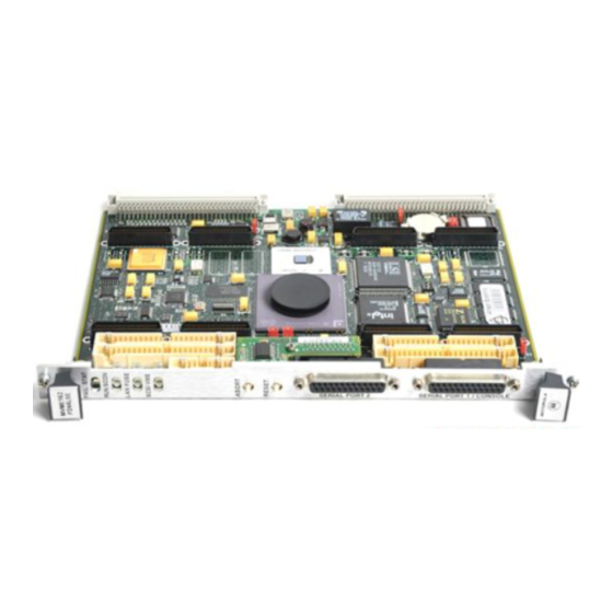
Summary of Contents for Motorola MVME162P4
- Page 1 MVME162P4 VME Embedded Controller Installation and Use V162PFXA/IH1 June 2000...
- Page 2 Printed in the United States of America. ® Motorola and the Motorola logo are registered trademarks of Motorola, Inc. MC68040™ and MC68060™ are trademarks of Motorola, Inc. IndustryPack™ and IP™ are trademarks of GreenSpring Computers, Inc. All other products mentioned in this document are trademarks or registered trademarks of...
- Page 3 The safety precautions listed below represent warnings of certain dangers of which Motorola is aware. You, as the user of the product, should follow these warnings and all other safety precautions necessary for the safe operation of the equipment in your operating environment.
- Page 4 Hersteller empfohlenen Typ. Entsorgung gebrauchter Batterien nach Angaben des Herstellers. Vorsicht CE Notice (European Community) Motorola Computer Group products with the CE marking comply with the EMC Directive (89/336/EEC). Compliance with this directive implies conformity to the following European Norms:...
- Page 5 While reasonable efforts have been made to assure the accuracy of this document, Motorola, Inc. assumes no liability resulting from any omissions in this document, or from the use of the information obtained therein. Motorola reserves the right to revise this document and to make changes from time to time in the content hereof without obligation of Motorola to notify any person of such revision or changes.
- Page 6 (b)(3) of the Rights in Technical Data clause at DFARS 252.227-7013 (Nov. 1995) and of the Rights in Noncommercial Computer Software and Documentation clause at DFARS 252.227-7014 (Jun. 1995). Motorola, Inc. Computer Group 2900 South Diablo Way Tempe, Arizona 85282...
- Page 7 General-Purpose Readable Switch (S4 Pin 5) ..........1-16 IP DMA Snoop Control (S5 Pins 1/2) ..............1-17 IP Reset Mode (S5 Pin 3) .................1-18 Flash Write Enable Mode (S5 Pin 4) ..............1-19 MCECC DRAM Size (S6)................1-19 Installation Instructions....................1-21 IP Installation on the MVME162P4 ..............1-21 MVME162P4 Installation.................1-22...
- Page 8 System Considerations ..................1-24 Serial Connections.................... 1-26 CHAPTER 2 Startup and Operation Introduction ....................... 2-1 Front Panel Switches and Indicators ..............2-1 Initial Conditions ....................... 2-2 Applying Power ......................2-2 Pre-Startup Checklist....................2-3 Bringing up the Board ....................2-4 Autoboot ......................2-9 ROMboot......................
- Page 9 ASICs........................4-3 Block Diagram ......................4-4 Functional Description....................4-4 Data Bus Structure ....................4-4 Microprocessor ....................4-6 MC68xx040 Cache ..................4-6 No-VMEbus-Interface Option ................4-7 Memory Options ....................4-7 DRAM ......................4-7 SRAM......................4-8 About the Battery..................4-9 EPROM and Flash Memory ..............4-10 Battery-Backed-Up RAM and Clock..............4-11 VMEbus Interface and VMEchip2 ..............4-12 I/O Interfaces ....................4-12 Serial Communications Interface ..............4-12 IndustryPack (IP) Interfaces ..............4-16...
- Page 10 APPENDIX A Specifications Board Specifications....................A-1 Cooling Requirements ....................A-2 Special Considerations for Elevated-Temperature Operation ......A-2 EMC Regulatory Compliance .................. A-3 APPENDIX B Troubleshooting Solving Startup Problems ..................B-1 APPENDIX C Network Controller Data Network Controller Modules Supported ..............C-1 APPENDIX D Disk/Tape Controller Data Controller Modules Supported .................
- Page 11 List of Figures Figure 1-1. MVME162P4 Board Layout ..............1-6 Figure 1-2. Serial Interface Module, Connector Side ..........1-9 Figure 1-3. EIA-232-D Connections to MVME712M (Sheet 1 of 6)......1-29 Figure 1-4. EIA-530 Connections (Sheet 1 of 2) .............1-35 Figure 1-5. EIA-232-D Connections to MVME712A/AM/-12/-13 (Sheet 1 of 4) ..1-37 Figure 1-6.
- Page 12 Table 1-3. MC2 DRAM Size Settings ..............1-16 Table 1-4. Switch S5 Snoop Control Encoding ............1-18 Table 1-5. MCECC DRAM Size Settings..............1-22 Table 2-1. MVME162P4 Front Panel Controls ............2-1 Table 2-2. Software-Readable Switches ..............2-6 Table 3-1. Memory Offsets with 162Bug ..............3-4 Table 3-2.
- Page 13 (ASIC) which combines the functions previously covered by the MC2 chip, the IP2 chip, and the MCECC chip in a single ASIC. As of the publication date, the information presented in this manual applies to the following MVME162P4 models: Model Number Characteristics...
- Page 14 MVME162P4 VME embedded controller. The subsequent sections detail cooling requirements and EMC regulatory compliance. Appendix B, Troubleshooting, includes simple troubleshooting steps in the event that you have difficulty with your MVME162P4 VME embedded controller. Appendix C, Network Controller Data, describes the VMEbus Network Controller modules that are supported by the 162Bug firmware.
- Page 15 Motorola Computer Group Reader Comments DW164 2900 S. Diablo Way Tempe, Arizona 85282 You can also submit comments to the following e-mail address: reader-comments@mcg.mot.com In all your correspondence, please list your name, position, and company. Be sure to include the title and part number of the manual and tell how you used it.
- Page 16 bold is used for user input that you type just as it appears; it is also used for commands, options and arguments to commands, and names of programs, directories and files. italic is used for names of variables to which you assign values. Italic is also used for comments in screen displays and examples, and to introduce new terms.
- Page 17 1Hardware Preparation and Installation Introduction This chapter provides unpacking instructions, hardware preparation guidelines, and installation instructions for the MVME162P4 VME Embedded Controller. Hardware preparation of the MVME712 series transition modules compatible with this board is described in separate manuals. Getting Started This section supplies an overview of startup procedures applicable to the MVME162P4.
- Page 18 Programmer’s Reference Guide, listed in applications. Appendix E, Related Documentation. Equipment Required The following equipment is necessary to complete an MVME162P4 system: VME system enclosure System console terminal Operating system (and / or application software) Disk drives (and / or other I/O) and controllers...
- Page 19 MVME162P4 board. Use ESD Motorola strongly recommends the use of an antistatic wrist strap and a conductive foam pad when you install or upgrade the board. Electronic components can be extremely sensitive to ESD. After removing the board...
- Page 20 MVME162P4, you may need to reconfigure hardware to some extent before installing the module. Most options on the MVME162P4 are under software control: By setting bits in control registers after installing the module in a system, you can modify its configuration. (The MVME162P4 registers are described in Chapter 3 under ENV –...


