Table of Contents
Advertisement
Quick Links
SIMATIC NET
Industrial Remote Communication -
Remote Networks
SCALANCE MUM856-1
Operating Instructions
02/2023
C79000-G8976-C628-05
Preface
Safety notices
Security recommendations
Description of the device
Assembly and disassembly
Connecting up
Maintenance and cleaning
Troubleshooting
Technical specifications
Dimension drawings
Approvals
1
2
3
4
5
6
7
8
9
10
Advertisement
Table of Contents

Related Manuals for Siemens SIMATIC NET SCALANCE MUM856-1


Summary of Contents for Siemens SIMATIC NET SCALANCE MUM856-1
- Page 1 Preface Safety notices Security recommendations SIMATIC NET Description of the device Industrial Remote Communication - Remote Networks Assembly and disassembly SCALANCE MUM856-1 Operating Instructions Connecting up Maintenance and cleaning Troubleshooting Technical specifications Dimension drawings Approvals 02/2023 C79000-G8976-C628-05...
- Page 2 Note the following: WARNING Siemens products may only be used for the applications described in the catalog and in the relevant technical documentation. If products and components from other manufacturers are used, these must be recommended or approved by Siemens. Proper transport, storage, installation, assembly, commissioning, operation and maintenance are required to ensure that the products operate safely and without any problems.
-
Page 3: Preface
These operating instructions apply to the following firmware version: • SCALANCE M-800/S615 version 7.2 or later You will find the article numbers for the Siemens products of relevance here in the following catalogs: • SIMATIC NET Industrial Communication / Industrial Identification, catalog IK PI •... - Page 4 (https:// support.industry.siemens.com/cs/ww/en/view/84922825) SIMATIC NET manuals You will find SIMATIC NET manuals on the Internet pages of Siemens Industry Online Support: • using the search function: Link to Siemens Industry Online Support (https://support.industry.siemens.com/cs/ww/en/) Enter the entry ID of the relevant manual as the search item.
- Page 5 Check regularly for new firmware/software versions or security updates and apply them. After the release of a new version, previous versions are no longer supported and are not maintained. Error/fault If a fault develops, send the device to your SIEMENS representative for repair. Repairs on-site are not permitted. Decommissioning Shut down the device properly to prevent unauthorized persons from accessing confidential data in the device memory.
- Page 6 You will find license conditions in the following documents on the supplied data medium: • OSS_SCALANCE_MuM856_86.pdf SIMATIC NET glossary The SIMATIC NET glossary describes terms that may be used in this document. You will find the SIMATIC NET glossary in the Siemens Industry Online Support at the following address: 50305045 (https://support.industry.siemens.com/cs/ww/en/view/50305045) Trademarks The following and possibly other names not identified by the registered trademark sign ®...
-
Page 7: Table Of Contents
Table of contents Preface ..............................3 Safety notices ............................9 Security recommendations........................11 Security recommendations....................11 Available services....................... 15 Description of the device ........................19 Structure of the type designation ..................19 Product characteristics ....................... 19 Device view ........................20 Scope of delivery ....................... - Page 8 Table of contents Maintenance and cleaning ........................57 Troubleshooting........................... 59 Downloading new firmware using TFTP without WBM and CLI..........59 Restoring the factory settings..................... 60 Technical specifications ........................63 Dimension drawings ..........................69 Approvals ............................. 73 10.1 EC declaration of conformity ....................74 10.1.1 RoHS ..........................
-
Page 9: Safety Notices
Safety notices CAUTION To prevent injury and damage, read the manual before using the device. Read the safety notices Note the following safety notices. These relate to the entire working life of the device. You should also read the safety notices relating to handling in the individual sections, particularly in the sections "Installation"... - Page 10 Safety notices SCALANCE MUM856-1 Operating Instructions, 02/2023, C79000-G8976-C628-05...
-
Page 11: Security Recommendations
• For data transmission via a non-secure network, use an encrypted VPN tunnel (IPsec, OpenVPN). • Check the user documentation of other Siemens products that are used together with the device for additional security recommendations. • Using remote logging, ensure that the system protocols are forwarded to a central logging server. - Page 12 • Verify certificates based on the fingerprint on the server and client side to prevent "man in the middle" attacks. Use a second, secure transmission path for this. • Before sending the device to Siemens for repair, replace the current certificates and keys with temporary disposable certificates and keys, which can be destroyed when the device is returned.
- Page 13 Implementation Information Disclosure Vulnerability (for example, BEAST). • Ensure that the latest firmware version is installed, including all security-related patches. You can find the latest information on security patches for Siemens products at the Industrial Security (https://www.siemens.com/industrialsecurity) or ProductCERT Security Advisories (https://www.siemens.com/cert/en/cert-security-advisories.htm) website.
- Page 14 Security recommendations 2.1 Security recommendations • Use the authentication and encryption mechanisms of SNMPv3 if possible. Use strong passwords. • Configuration files can be downloaded from the device. Ensure that configuration files are adequately protected. Configuration files can be password protected during download. You enter passwords on the WBM page "System >...
-
Page 15: Available Services
Security recommendations 2.2 Available services • If a secure alternative is available for a protocol, use it. The following protocols provide secure alternatives: – SNMPv1/v2 → SNMPv3 Check whether use of SNMPv1 is necessary. SNMPv1 is classified as non-secure. Use the option of preventing write access. - Page 16 UDP/1812 Closed Closed ✓ ✓ ✓ Optional UDP/1813 SFTP Server TCP/22 Outgoing only Outgoing on‐ ✓ ✓ ✓ ✓ Siemens Re‐ TCP/443 Outgoing only Outgoing on‐ ✓ Optional ✓ mote Serv‐ ice (cRSP/ SRS) SCALANCE MUM856-1 Operating Instructions, 02/2023, C79000-G8976-C628-05...
- Page 17 Security recommendations 2.2 Available services Service Protocol/ Default port status Configurable Authenti‐ Encryp‐ Port number cation tion Local access External ac‐ Port Serv‐ cess SINEMA RC HTTPS/443 Outgoing only Outgoing on‐ ✓ ✓ ✓ ✓ and TCP/UDP depending on the server configuration SMTP Client TCP/25...
- Page 18 Security recommendations 2.2 Available services The table includes the following columns: • Layer 2 service The Layer 2 services that the device supports. • Default status The default status of the service (open or closed). • Service configurable Indicates whether the service can be configured via WBM / CLI. Layer 2 service Default status Configurable...
-
Page 19: Description Of The Device
Description of the device Structure of the type designation Structure of the type designation The type designation of the device is made up of several parts that have the following meaning: Product characteristics Interfaces Functionality SCALANCE MUM856-1 Connectors for external antennas 4 x N-Connect Ethernet interface 1 x M12 Ethernet interface P1 LAN PoE, X-coded, 8-pin Power supply (direct) -
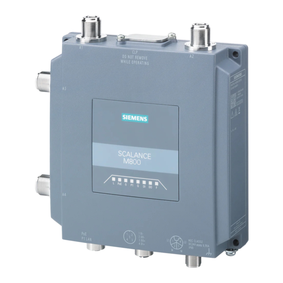
Page 20: Device View
Description of the device 3.4 Scope of delivery Device view ① A1 antenna port, female N-Connect type ② Screw-down cover: - for the reset button and - for the CLP slot ③ A2 antenna port, female N-Connect type ④ LED display ⑤... - Page 21 • One grounding screw • A product DVD Please check that the consignment you have received is complete. If the consignment is incomplete, contact your supplier or your local Siemens office. Note Not included with the product The following components do not ship with the product: •...
-
Page 22: Accessories
3.5 Accessories Accessories Technical data subject to change. You will find further information on the range of accessories in the Industry Mall (https:// mall.industry.siemens.com/mall/en/WW/Catalog/Products/10022025) Use the TIA Selection Tool (https://mall.industry.siemens.com/tst/) for configuring the device. 3.5.1 Installation Type Properties Article number Mounting adapter DIN rail Adapter for mounting on a 35mm DIN rail ac‐... - Page 23 Description of the device 3.5 Accessories Type Properties Article number ANT897-6ME Mobile wireless antenna with omnidirection‐ 6GK5897-4ME00-0AA0 al characteristic for public 3/4/5G mobile wire‐ less networks and private 5G networks world‐ wide; 600 .. 6000 MHz; antenna gain: 2...6 dBi, incl. N-Connect female connector, IP65;...
-
Page 24: Led Display
Description of the device 3.6 LED display LED display M800 Status Meaning Device turned off, no power supply. Green Device turned on, power supply present. The device is not supplied using PoE. Green The device is supplied using PoE. No VPN connection is established. Green All configured VPN connections are established. - Page 25 Description of the device 3.6 LED display Status Meaning There is no connection over the Ethernet interface P1. Green There is a connection over the Ethernet interface P1 (link). Flashing Data transfer over the Ethernet interface P1 green and yellow No reception or mobile wireless disabled Wrong PIN number or SIM card error Flashing red Signal strength very poor Flashing yel‐...
-
Page 26: Reset Button
Description of the device 3.7 Reset button Status Meaning No fault/error Yellow: Sleep mode is active. The device is starting up or an error has occurred. Possible errors/faults: • Wrong PIN number • The inserted CLP has an invalid or incompatible configuration Flashing red Firmware on CLP The device is performing a firmware update or downgrade. -
Page 27: Configuration License Plug
• CLP configuration: The removable data storage medium only saves the configuration data of the device. • CLP license: In addition to the configuration data, the removable data storage medium also contains a license that allows the use of Siemens Remote Services. NOTICE Loss of the degree of protection When the cover is not mounted correctly, the device loses its degree of protection IP65 and is not water and dust proof. - Page 28 – The configuration data of the device is stored in a secured memory area of the CLP. This secured memory area can only be accessed via the authentication of the Siemens device. – The device checks whether a CLP is inserted at one second intervals. If the device detects that the CLP has been removed, it restarts automatically.
-
Page 29: Assembly And Disassembly
Assembly and disassembly Safety notices for installation Safety notices When installing the device, keep to the safety notices listed below. NOTICE Improper mounting Improper mounting may damage the device or impair its operation. • Before mounting the device, always ensure that there is no visible damage to the device. •... - Page 30 Assembly and disassembly 4.1 Safety notices for installation WARNING If the device is installed in a cabinet, the inner temperature of the cabinet corresponds to the ambient temperature of the device. WARNING The device is intended for indoor use only. Safety notices on use in hazardous areas General safety notices relating to protection against explosion WARNING When used in hazardous environments corresponding to Class I, Division 2 or Class I, Zone 2,...
- Page 31 Assembly and disassembly 4.1 Safety notices for installation WARNING EXPLOSION HAZARD The equipment is intended to be installed within an enclosure/control cabinet. The inner service temperature of the enclosure/control cabinet corresponds to the ambient temperature of the module. Use cables with a maximum permitted operating temperature of at least 20 °C higher than the maximum ambient temperature.
-
Page 32: Types Of Installation
Assembly and disassembly 4.3 Wall mounting WARNING If the temperature at the cable or housing socket or at the branching points of the cables exceeds 60 °C, special precautions must be taken. If the equipment is operated at ambient temperatures in excess of 40 °C, only use cables with permitted operating temperature of at least 80 ℃. -
Page 33: Din Rail Mounting
Assembly and disassembly 4.4 DIN rail mounting 4. Connect the power supply, refer to the section "Power supply (Page 44)". 5. Fit the antennas, refer to the section "Antennas (Page 47)". DIN rail mounting 4.4.1 Installation with the DIN rail mounting adapter The DIN rail mounting adapter is not included with the product, see Accessories (Page 22). Installation 1. - Page 34 Assembly and disassembly 4.4 DIN rail mounting 4. Press the device against the DIN rail until the DIN rail slider catch locks into place. 5. Connect the power supply, refer to the section "Power supply (Page 44)". 6. Fit the antennas, refer to the section "Antennas (Page 47)". Uninstalling 1.
-
Page 35: Mounting With Bracket Support
Assembly and disassembly 4.4 DIN rail mounting 4. Tilt the device forward and remove the device from the DIN rail. 5. Loosen the screws of the DIN rail mounting adapter completely. 4.4.2 Mounting with bracket support With the bracket support the device can be mounted on a DIN rail rotated through 90° The DIN rail mounting adapter and bracket support are not included with the product, see Accessories (Page 22). - Page 36 Assembly and disassembly 4.4 DIN rail mounting Installation 1. Screw (M3, tightening torque 0.7 Nm) the bracket support to the DIN rail mounting adapter . The mounting material ships with the product. 2. Screw (tightening torque 0.7 Nm) the bracket support to the side of the device.
- Page 37 Assembly and disassembly 4.4 DIN rail mounting 5. Press the device against the DIN rail until the DIN rail slider catch locks into place. 6. Connect the power supply, refer to the section "Power supply (Page 44)". 7. Fit the antennas, refer to the section "Antennas (Page 47)". Uninstalling 1.
- Page 38 Assembly and disassembly 4.4 DIN rail mounting 4. Tilt the device forward and remove the device from the DIN rail. 5. Loosen the screws completely. SCALANCE MUM856-1 Operating Instructions, 02/2023, C79000-G8976-C628-05...
-
Page 39: Connecting Up
Connecting up Safety when connecting up Safety notices When connecting up the device, keep to the safety notices listed below. Note Strain relief for the Ethernet cables In order to avoid mechanical stress on the Ethernet cables and resulting interruption of the contact, fasten the cables at a short distance from the connector using a cable guide or busbar. - Page 40 Connecting up 5.1 Safety when connecting up WARNING Power supply The device is designed for operation with Safety Extra-Low Voltage (SELV) that can be connected directly by a Limited Power Source (LPS). The power supply therefore needs to meet at least one of the following conditions: •...
- Page 41 Connecting up 5.1 Safety when connecting up NOTICE Suitable fuse for the power supply cables (corresponds to "Limited Energy") The current on the terminal may not exceed 3 A. Use a fuse for the power supply that is suitable for protection of AC/DC power supply circuits * and protects against currents >...
- Page 42 Connecting up 5.1 Safety when connecting up WARNING EXPLOSION HAZARD Do not press the reset button if there is a potentially explosive atmosphere. WARNING Unsuitable cables or connectors Risk of explosion in hazardous areas • Only use connectors that meet the requirements of the relevant type of protection. •...
- Page 43 Connecting up 5.1 Safety when connecting up WARNING Insufficient isolation of intrinsically safe and non-intrinsically safe circuits Risk of explosion in hazardous areas • When connecting intrinsically safe and non-intrinsically safe circuits, ensure that the galvanic isolation is performed properly in compliance with local regulations (e.g. IEC 60079-14).
-
Page 44: Power Supply
Connecting up 5.2 Power supply WARNING Restricted area of application This equipment is suitable for use in Class I, Zone 2, Group IIC or non-hazardous locations only. Power supply Note Galvanic isolation of the power supply unit To ensure dielectric strength according to IEEE 802.3, the supplying 24 V power supply unit must be galvanically isolated with a dielectric strength of 1500 VAC. - Page 45 Connecting up 5.2 Power supply Position and pin assignment ① M12 Ethernet interface P1 LAN PoE, X-coded, 8-pin The power can also be supplied via this interface (Power over Ethernet). Pin assignment, see Ethernet (Page 46) ② M12 interface, direct infeed, L-coded, 4-pin The 4-pin M12 socket has the following pin assignment: Color Signal...
-
Page 46: Ethernet
Connecting up 5.3 Ethernet Note The requirements of EN61000-4-5, "Surge Immunity Test" on power supply lines with 24 VDC are met only when a Blitzductor is used: 24 VDC: BVT AVD 24 type no. 918 422 Vendor: DEHN+SÖHNE GmbH+Co.KG, Hans Dehn Str. 1, Postfach 1640, D - 92306 Neumarkt, Germany Ethernet For connection to Industrial Ethernet at 10/100/1000 Mbps, the device has an M12 interface: X-... -
Page 47: Antennas
Connecting up 5.4 Antennas Antennas The SCALANCE MUM856-1 has 4 antenna ports of the type N-Connect female. Note Use the antennas from the range of accessories for the device. You will find more detailed information in "Accessories (Page 22)". If you use a different antenna, there is no guarantee that the device will function according to the specification. - Page 48 Connecting up 5.4 Antennas Connecting antennas Follow the steps below to connect a cable for an external antenna: 1. Remove the protective cap from the affected N-Connector on the device. Note Antennas • A1+ A2 An antenna must always be connected to the antenna connectors in order to use 3/4/5G connectivity.
-
Page 49: Sim Card
Connecting up 5.5 SIM card Signal quality During installation make sure that there is a good signal strength of > -73 dBm. If the "Q" LED is lit permanently, the signal quality is good. For more detailed information, refer to the section "LED display (Page 24)". Avoid large metallic objects in the immediate vicinity. - Page 50 Connecting up 5.5 SIM card Inserting the SIM card 1. Remove the cover. 2. Press the tray with index finger and move it slightly upwards. The tray opens. 3. Insert the SIM card. 4. Close the tray. SCALANCE MUM856-1 Operating Instructions, 02/2023, C79000-G8976-C628-05...
-
Page 51: Grounding
Connecting up 5.6 Grounding 5. Lightly push the tray down with your finger until it locks into place. 6. Set the cover on again. Grounding EMC disturbances are diverted to ground via the functional ground. This ensures the immunity of the data transmission. The grounding screw is identified by the following symbol for the functional ground SCALANCE MUM856-1 Operating Instructions, 02/2023, C79000-G8976-C628-05... -
Page 52: Digital Input/Output
Connecting up 5.7 Digital input/output Protective earth/functional ground The connection of the reference potential surface with the protective earth system is normally in the cabinet close to the power feed-in. This earth conducts fault currents to ground safely and according to DIN/VDE 0100 is a protective earth to protect people, animals and property from too high contact voltages. - Page 53 Connecting up 5.7 Digital input/output Rules for wiring • To wire the digital input/output, use a copper cable of category AWG18-16 or a cable with a cross-section of 0.75 to 1.5 mm • Always wire the digital input/output in pairs. • The maximum permitted cable length is 3 m. Position / Assignment Example: Ground...
-
Page 54: Replacing A Clp
Connecting up 5.8 Replacing a CLP Replacing a CLP Position The CLP slot is at the top of the device enclosure under a cover, see Reset button. ① M3 screws (Torx T10) ② Slot cover ③ Removing a CLP Note Loss of the configuration The reset button is located directly beside the slot for the CLP. - Page 55 Connecting up 5.8 Replacing a CLP ③ 3. To release the CLP , insert a screwdriver between the front edge of the CLP (A) and the slot. 4. Remove the CLP from the slot. 5. Close the slot cover (torque 0.8 Nm) to ensure that the device maintains the degree of protection IP65.
- Page 56 Connecting up 5.8 Replacing a CLP SCALANCE MUM856-1 Operating Instructions, 02/2023, C79000-G8976-C628-05...
-
Page 57: Maintenance And Cleaning
Maintenance and cleaning WARNING Unauthorized repair of devices in explosion-proof design Risk of explosion in hazardous areas • Repair work may only be performed by personnel authorized by Siemens. WARNING Impermissible accessories and spare parts Risk of explosion in hazardous areas •... - Page 58 Maintenance and cleaning SCALANCE MUM856-1 Operating Instructions, 02/2023, C79000-G8976-C628-05...
-
Page 59: Troubleshooting
Downloading new firmware using TFTP without WBM and CLI Firmware The firmware is signed and encrypted. This ensures that only firmware created by Siemens can be downloaded to the device. You can download new firmware to the device using TFTP. To do this, the device does not need to be reachable either using Web Based Management (WBM) or using the Command Line Interface (CLI). -
Page 60: Restoring The Factory Settings
Troubleshooting 7.2 Restoring the factory settings Restoring the factory settings NOTICE Previous settings If you reset, all the settings you have made will be overwritten by factory defaults. NOTICE Inadvertent reset An inadvertent reset can cause disturbances and failures in a configured network with further consequences. - Page 61 Troubleshooting 7.2 Restoring the factory settings Via the configuration You will find detailed information on resetting the device parameters using the WBM and CLI in the configuration manuals: • Web Based Management, section "Restart" • Command Line Interface, section "Reset and Defaults" SCALANCE MUM856-1 Operating Instructions, 02/2023, C79000-G8976-C628-05...
- Page 62 Troubleshooting 7.2 Restoring the factory settings SCALANCE MUM856-1 Operating Instructions, 02/2023, C79000-G8976-C628-05...
-
Page 63: Technical Specifications
Technical specifications The following technical specifications apply to SCALANCE MUM856-1. Technical specifications Data transfer Ethernet transmission rate 10 Mbps, 100 Mbps, 1000 Mbps Wireless transmission rate • Downlink: up to 1000 Mbps • Uplink: up to 500 Mbps • Downlink: up to 1000 Mbps • Uplink: up to 200 Mbps UMTS •... - Page 64 Technical specifications Technical specifications Frequency bands 6GK5856-2EA00-3DA1 (EU) 5G Standalone (SA) n1, n3, n5, n7, n8, n12, n20, n28, n38, n40, n41, n48, n71, n77, n78, n79 5G Non-Standalone n1, n3, n5, n7, n8, n20, n28, n38, n40, (NSA) n41, n48, n66, n77, n78, n79 B1, B2, B3, B4, B5, B7, B8, B12, B13, B14, B17, B18, B19, B20, B25, B26, B28, B29, B30, B32, B66, B71, B34,...
- Page 65 Technical specifications Technical specifications Digital input Quantity Design M12 socket, A-coded Status "0" -30V to 3 V DC Status "1" 10 V DC .. 30 V Max. input current 8 mA Max. cable length < 3 m Cables should be routed in pairs Properties Input isolated from electronics Digital output...
- Page 66 – To establish a VPN (Virtual Pri‐ vate Network), the following functions are available – Up to 20 connections – IPsec VPN, OpenVPN (as client) • SINEMA RC client • Proxy server • Siemens Remote Service (SRS) SCALANCE MUM856-1 Operating Instructions, 02/2023, C79000-G8976-C628-05...
- Page 67 Technical specifications Technical specifications Monitoring / diagnostics / maintenance • LEDs Display of operating statuses via the LED display. You will find addi‐ tional information on this in the op‐ erating instructions of the device. • Logging Events can be logged for monitor‐ ing.
- Page 68 Technical specifications SCALANCE MUM856-1 Operating Instructions, 02/2023, C79000-G8976-C628-05...
-
Page 69: Dimension Drawings
Dimension drawings Note CAx data You can find the CAx data on the Internet at (https://www.automation.siemens.com/bilddb/ index.aspx?lang=en) 1. Click on the "CAx data" link in the "Direct Links" area. The Industry Image Database page is loaded. 2. Enter the name or article number of the product in the search filter. - Page 70 Dimension drawings Side view Top view SCALANCE MUM856-1 Operating Instructions, 02/2023, C79000-G8976-C628-05...
- Page 71 Dimension drawings Rear view SCALANCE MUM856-1 Operating Instructions, 02/2023, C79000-G8976-C628-05...
- Page 72 Dimension drawings SCALANCE MUM856-1 Operating Instructions, 02/2023, C79000-G8976-C628-05...
-
Page 73: Approvals
28821/cert) National approvals You can find an overview of the country-specific wireless approvals of SIMATIC NET devices on the Internet pages of Siemens Industry Online Support. You can find the link to the document on the following page ik-Info (https://www.siemens.com/mobilenetwork-approvals) Installation guidelines... -
Page 74: Ec Declaration Of Conformity
Process Automation DE-76187 Karlsruhe Germany You can find the current EU declaration of conformity for these products on the Internet pages under Siemens Industry Online Support (https:// support.industry.siemens.com/cs/ww/en/ps/28821/cert). The products described in this document meet the requirements of the following EC directives: •... -
Page 75: Rohs
Approvals 10.1 EC declaration of conformity 10.1.1 RoHS RoHS directive (restriction of the use of certain hazardous substances) The SIMATIC NET products described in these operating instructions meet the requirements of the EC directive 2011/65/EC for the restriction of the use of certain hazardous substances in electrical and electronic equipment. -
Page 76: Efficient Use Of The Radio Spectrum
Approvals 10.1 EC declaration of conformity • EN 55011 Industrial, scientific and medical (ISM) radio-frequency equipment – Electromagnetic dis‐ turbance characteristics – Limits and methods of measurement • EN 55032 Electromagnetic compatibility of multimedia equipment – Emission requirements • EN 55035 Electromagnetic compatibility of multimedia equipment - Immunity requirements •... -
Page 77: Other Technical Standards
Manchester M20 2UR United Kingdom You can find the current UK Declaration of Conformity for these products on the Internet pages under Siemens Industry Online Support (https:// support.industry.siemens.com/cs/ww/en/ps/28821/cert). The SIMATIC NET product described in these operating instructions meets the requirements of the following directives: •... -
Page 78: The Restriction Of The Use Of Certain Hazardous Substances In Electrical And Electronic Equipment Regulations 2012
Approvals 10.2 UK Declaration of Conformity 10.2.1 The Restriction of the Use of Certain Hazardous Substances in Electrical and Electronic Equipment Regulations 2012 Restriction of the use of certain hazardous substances The SIMATIC NET products described in these operating instructions meet the requirements of "The Restriction of the Use of Certain Hazardous Substances in Electrical and Electronic Equipment Regulations 2012". -
Page 79: Efficient Use Of The Radio Spectrum
Approvals 10.2 UK Declaration of Conformity • ETSI EN 301 489‑52 Electromagnetic Compatibility (EMC) standard for radio equipment and services; Part 52: Specific conditions for cellular communication mobile and portable (UE) radio and ancillary equipment • EN 55011 Industrial, scientific and medical (ISM) radio-frequency equipment – Electromagnetic dis‐ turbance characteristics –... -
Page 80: Other Technical Standards
Process Automation DE-76187 Karlsruhe Germany You can find the current Supplier's declaration of conformity for these products on the Internet pages under Siemens Industry Online Support (https:// support.industry.siemens.com/cs/ww/en/ps/28821/cert) As required by the following Notices: • Radiocommunications (Compliance Labelling - Devices) Notice 2014 made under section 182 of the Radiocommunications Act 1992;... -
Page 81: General Approvals
"SIMATIC NET Product Information Use of subassemblies/modules in a Zone 2 Hazardous Area". You will find this document • on the data medium that ships with some devices. • on the Internet pages under Siemens Industry Online Support (https:// support.industry.siemens.com/cs/ww/en/view/78381013). - Page 82 Approvals 10.4 General approvals The product meets the requirements of the standards: • EN/IEC 60079-7, GB 3836.8 • EN IEC/IEC 60079-0, GB 3836.1 You will find the current versions of the standards in the currently valid certificates. The product meets the requirements of the standards: •...
- Page 83 • Telecommunications (Labelling Notice for Customer Equipment and Customer Cabling) Instrument 2015 made under section 407 of the Telecommunications Act 1997 You can find the current declaration of conformity for these products on the Internet pages under Siemens Industry Online Support (https://support.industry.siemens.com/cs/ww/en/ps/ 15914/cert)
- Page 84 Approvals 10.4 General approvals Products Product name Standards Australia New Zealand SCALANCE MUM856-1 Marking for the customs union EAC (Eurasian Conformity) Eurasian Economic Union of Russia, Belarus, Armenia, Kazakhstan and Kyrgyzstan Declaration of conformity according to the technical regulations of the customs union (TR ZU) Railway approval The product meets the requirements of the railroad standard: •...
-
Page 85: Index
Index Accessories, 22 Glossary, 6 Antennas, 48 Grounding, 51 Article numbers, 3 Installation Button Wall mounting, 32 Reset, 26 with bracket support, 36 with DIN rail mounting adapter, 33 Interfaces, 63, 64, 65, 66, 67 Cables Permissible lengths, 63, 64, 65, 66, 67 CAx data, 69 LED display, 24, 25, 26 Certification ID, 3 CLP, 27 Function, 28 Replacing, 54... - Page 86 Index Technical specifications, 63, 64, 65, 66, 67 Type designations, 19 Wall mounting, 32 SCALANCE MUM856-1 Operating Instructions, 02/2023, C79000-G8976-C628-05...