Table of Contents
Advertisement
Quick Links
Advertisement
Table of Contents

Related Manuals for ABB i-bus VC/S 4 1 Series


Summary of Contents for ABB i-bus VC/S 4 1 Series
- Page 1 — PRODUCT MANUAL ABB i-bus® KNX VC/S 4.x.1 Valve drive controller...
-
Page 2: Table Of Contents
ABB i-bus® KNX TABLE OF CONTENTS Table of contents About this document................................Using the product manual ................................Legal disclaimer ....................................Explanation of symbols .................................. Safety ....................................General safety instructions ................................Qualification of the specialist personnel............................ Proper use ......................................Product overview ................................. 10 Device description................................... - Page 3 ABB i-bus® KNX TABLE OF CONTENTS Parameters ................................... 33 General....................................... 33 Parameter window ..................................34 7.2.1 Basic settings ................................34 7.2.2 Manual operation ................................35 7.2.3 Channel X ..................................36 Overview of parameters................................. 51 Parameter descriptions.................................. 54 7.4.1 Economy heating reduction............................54 7.4.2...
- Page 4 ABB i-bus® KNX TABLE OF CONTENTS 7.4.51 Weighting of internal measurement ......................... 84 7.4.52 Basic load active when controller off........................84 7.4.53 Basic-stage heating [actuator] ..........................85 7.4.54 Basic-stage heating [controller] ..........................85 7.4.55 Basic-stage cooling [actuator] ........................... 86 7.4.56 Basic-stage cooling [controller] ..........................86 7.4.57...
- Page 5 ABB i-bus® KNX TABLE OF CONTENTS 7.4.109 Reset purge cycle from control value greater than or equal to ................119 7.4.110 Send status values [analog room control unit]....................... 119 7.4.111 Send status values [binary input] ..........................119 7.4.112 Send status values [window contact]........................120 7.4.113...
- Page 6 ABB i-bus® KNX TABLE OF CONTENTS Group objects..................................150 Overview of group objects ................................150 Group objects, general ................................... 151 Group objects, Channel x - General.............................. 152 Group objects, Channel X - Valve X .............................. 154 Group objects, Channel X - Input x............................... 155 Group objects Channel X –...
-
Page 7: About This Document
ABB i-bus® KNX device. Legal disclaimer ABB AG reserves the right to make changes to the product or modify the contents of this document without prior notice. The agreed properties are definitive for any orders placed. ABB AG does not accept any responsibility whatsoever for potential errors or possible lack of information in this document. - Page 8 ABB i-bus® KNX ABOUT THIS DOCUMENT Notes and warnings are represented as follows in this manual: DANGER This symbol is a warning about electrical voltage and indicates high-risk hazards that will definitely result in death or serious injury unless avoided. DANGER Indicates high-risk hazards that will definitely result in death or serious injury unless avoided.
-
Page 9: Safety
ABB i-bus® KNX SAFETY Safety General safety instructions ▶ Protect the device from moisture, dirt and damage during transport, storage and operation. ▶ Operate the device only in a closed housing (distribution board). ▶ Operate the device only within the specified technical data. -
Page 10: Product Overview
The devices are KNX-certified and can be used as products in a KNX system → EU declaration of con- formity. The devices are powered via the bus (ABB i-bus® KNX) and require no additional auxiliary voltage supply. The connection to the bus is made via a bus connection terminal on the front of the housing. The loads are connected to the outputs using screw terminals →... -
Page 11: Inputs
ABB i-bus® KNX PRODUCT OVERVIEW Valve outputs VC/S 4.1.1 VC/S 4.2.1 Thermoelectric Valve Drives (PWM) Magnetic valve drives (open/closed) Tab. 4: Valve outputs Physical inputs VC/S 4.1.1 VC/S 4.2.1 Analog room control units Binary sensors (floating) Temperature sensors Tab. 5: Physical inputs 3.4.1... -
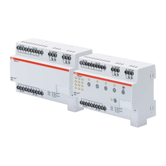
Page 12: Valve Drive Controller Vc/S 4.1.1, Mdrc
ABB i-bus® KNX PRODUCT OVERVIEW Valve Drive Controller VC/S 4.1.1, MDRC Fig. 1: Valve Drive Controller VC/S 4.1.1 Product manual | EN-US | VC/S 4.x.1 | 2CDC508220D0211 Rev. B 12 Note about navigation in the PDF: Key combination 'Alt + left arrow' jumps to the previous view/page... -
Page 13: Dimension Drawing
ABB i-bus® KNX PRODUCT OVERVIEW 3.5.1 Dimension drawing Fig. 2: Dimension drawing Product manual | EN-US | VC/S 4.x.1 | 2CDC508220D0211 Rev. B 13 Note about navigation in the PDF: Key combination 'Alt + left arrow' jumps to the previous view/page... -
Page 14: Connection Diagram
ABB i-bus® KNX PRODUCT OVERVIEW 3.5.2 Connection diagram Fig. 3: Connection diagram VC/S 4.1.1 — Legend 2 Programming LED 6 Input 3 Programming button 7 Binary input 4 Bus connection terminal 8 Valve output 5 Cover cap Product manual | EN-US | VC/S 4.x.1 | 2CDC508220D0211 Rev. B 14... -
Page 15: Operating And Display Elements
ABB i-bus® KNX PRODUCT OVERVIEW 3.5.3 Operating and display elements Operating control/LED Description/function Display Assignment of the physical address LED On: Device in programming mode Programming button/LED Tab. 8: Operating and display elements Product manual | EN-US | VC/S 4.x.1 | 2CDC508220D0211 Rev. B 15... -
Page 16: Technical Data
ABB i-bus® KNX PRODUCT OVERVIEW 3.5.4 Technical data 3.5.4.1 General technical data Device Dimensions 90 × 140 × 63.5 mm (H x W x D) Mounting width in space units 8 modules, 17.5 mm each Weight 0.27 kg Mounting position Mounting variant 35 mm mounting rail... - Page 17 Maximum number of assignments Tab. 12: Device type Note Observe software information on the website → www.abb.com/knx. Product manual | EN-US | VC/S 4.x.1 | 2CDC508220D0211 Rev. B 17 Note about navigation in the PDF: Key combination 'Alt + left arrow' jumps to the previous view/page...
-
Page 18: Valve Drive Controller Vc/S 4.2.1, Mdrc
ABB i-bus® KNX PRODUCT OVERVIEW Valve Drive Controller VC/S 4.2.1, MDRC Fig. 4: Valve Drive Controller VC/S 4.2.1 Product manual | EN-US | VC/S 4.x.1 | 2CDC508220D0211 Rev. B 18 Note about navigation in the PDF: Key combination 'Alt + left arrow' jumps to the previous view/page... -
Page 19: Dimension Drawing
ABB i-bus® KNX PRODUCT OVERVIEW 3.6.1 Dimension drawing Fig. 5: Dimension drawing Product manual | EN-US | VC/S 4.x.1 | 2CDC508220D0211 Rev. B 19 Note about navigation in the PDF: Key combination 'Alt + left arrow' jumps to the previous view/page... -
Page 20: Connection Diagram
ABB i-bus® KNX PRODUCT OVERVIEW 3.6.2 Connection diagram Fig. 6: Connection diagram VC/S 4.2.2 — Legend 1 Label carriers 7 Binary input 2 Programming LED 8 Valve output 3 Programming button 9 Reset button / valve output error LED 4 Bus connection terminal... -
Page 21: Operating And Display Elements
ABB i-bus® KNX PRODUCT OVERVIEW 3.6.3 Operating and display elements Operating control/LED Description/function Display Assignment of the physical address LED On: Device in programming mode Programming button/LED Tab. 13: Operating and display elements 3.6.3.1 Manual mode Operating control/LED Description/function Display Activates the... - Page 22 ABB i-bus® KNX PRODUCT OVERVIEW 3.6.3.2 KNX operation Operating control/LED Description/function Display Manual operation Manual operation Activates the mode with LED On: active long button push > 5 s LED Off: KNX operation active LED flashes when button is pushed: Manual operation...
-
Page 23: Technical Data
ABB i-bus® KNX PRODUCT OVERVIEW 3.6.4 Technical data 3.6.4.1 General technical data Device Dimensions 90 × 140 × 63.5 mm (H x W x D) Mounting width in space units 8 modules, 17.5 mm each Weight 0.28 kg Mounting position Mounting variant 35 mm mounting rail... - Page 24 Maximum number of assignments Tab. 19: Device type Note Observe software information on the website → www.abb.com/knx. Product manual | EN-US | VC/S 4.x.1 | 2CDC508220D0211 Rev. B 24 Note about navigation in the PDF: Key combination 'Alt + left arrow' jumps to the previous view/page...
-
Page 25: Function
The internal controller is activated in the function as a controller channel. The controller is used to process the data received at the inputs (actual values) or via the bus (ABB i-bus® KNX) (actual values, set- points and operating mode changes). The control values are calculated from the data received and trans- mitted to the outputs. - Page 26 ABB i-bus® KNX FUNCTION Temperature input monitoring The monitoring is activated in the parameter Error Operating mode receipt If no value is received on group object Operating mode normal (master) during the set time interval (→ parameter Time interval for cyclical monitoring ), the following actions are carried out: •...
-
Page 27: Integration Into I-Bus® Tool
For more information → parameter I-bus® Tool access i-bus® Tool can be downloaded free of charge from the company homepage (www.abb.com/knx). Special operating states The device's reaction if there is a bus voltage failure, after bus voltage recovery and after ETS download can be set in the device parameters. - Page 28 ABB i-bus® KNX FUNCTION Note The device will no longer operate after the application is uninstalled or the download is canceled. ▶ Download again. Product manual | EN-US | VC/S 4.x.1 | 2CDC508220D0211 Rev. B 28 Note about navigation in the PDF: Key combination 'Alt + left arrow'...
-
Page 29: Mounting And Installation
The device can be mounted in any position as required on a 35 mm mounting rail. The electrical connection to the loads is made using screw terminals. The connection to the bus (ABB i-bus® KNX) is made using the bus connection terminal supplied. The terminal assignment is lo- cated on the housing. -
Page 30: Connecting Analog Room Control Unit
ABB i-bus® KNX MOUNTING AND INSTALLATION Connecting analog room control unit 1. Connect analog room control unit to input a. 2. Connect temperature sensor to a different input (recommendation: input b). 3. Parametrize the temperature-sensor input as follows: • Temperature sensor type: NTC •... -
Page 31: Commissioning
ABB i-bus® KNX COMMISSIONING Commissioning Prerequisites for commissioning A PC with ETS and a connection to the bus (ABB i-bus® KNX), e.g. via a KNX interface, are required to commission the device. • Required ETS version: 4.0 or higher – from application V1.1: 5.0 or higher •... -
Page 32: Software/Application
6.5.2 Copying, exchanging and converting Update Copy Convert The following functions can be performed with the ETS application ABB Update • : Changes the application program to a higher or lower version while retaining the current con- figurations •... -
Page 33: Parameters
ABB i-bus® KNX PARAMETERS Parameters General Note ETS (Engineering Tool Software) is used to parameterize the device. The following sections describe the device parameters based on the parameter windows. The parameter windows have a dynamic design. Parameters are shown or hidden depending on the outputs’ parameter- ization and function. -
Page 34: Parameter Window
ABB i-bus® KNX PARAMETERS Parameter window 7.2.1 Parameter window Basic settings The basic settings for operating the device can be made in this parameter window. Fig. 8: Parameter window Basic settings This parameter window includes the following parameters: → S ending and switching delay after bus voltage recovery, Page 1 11 →... -
Page 35: Manual Operation
ABB i-bus® KNX PARAMETERS 7.2.2 Parameter window Manual operation The following settings can be made in this parameter window: Manual operation • Enable operating state • Automatically reset the device to operating state KNX operation More information: → M anual operation, Page 1 Fig. 9: Parameter window Manual operation... - Page 36 ABB i-bus® KNX PARAMETERS 7.2.3 Parameter window Channel X 7.2.3.1 Parameter window Application parameters The basic device settings can be made in this parameter window. Fig. 10: Parameter window Application parameters Product manual | EN-US | VC/S 4.x.1 | 2CDC508220D0211 Rev. B 36...
- Page 37 ABB i-bus® KNX PARAMETERS This parameter window includes the following parameters: → C hannel function, Page 9 3 → B asic-stage heating [controller], Page 8 5 → A dditional-stage heating, Page 1 44 →...
-
Page 38: Channel X
ABB i-bus® KNX PARAMETERS 7.2.3.2 Parameter window Channel function The following settings can be made in this parameter window: • Reaction after bus voltage recovery • Reaction after ETS download/reset Fig. 11: Channel function parameter window This parameter window includes the following parameters: →... - Page 39 ABB i-bus® KNX PARAMETERS 7.2.3.3 Parameter window Temperature controller The following settings can be made in this parameter window: • Parameterizing basic load • Send behavior of control values for the inactive operating mode • Sending behavior of the current room temperature (actual temperature) Fig. 12: Parameter window Temperature controller...
- Page 40 ABB i-bus® KNX PARAMETERS 7.2.3.3.1 Parameter window Basic-stage heating The following settings can be made in this parameter window: • Control type • Limitation of the control range • Sending behavior of the control value • Activation and setting of temperature limitation Fig. 13: Basic-stage heating parameter window...
- Page 41 ABB i-bus® KNX PARAMETERS 7.2.3.3.2 Parameter window Basic-stage cooling The following settings can be made in this parameter window: • Control type • Limitation of the control range • Sending behavior of the control value • Activation and setting of temperature limitation Fig. 14: Basic-stage cooling parameter window...
- Page 42 ABB i-bus® KNX PARAMETERS 7.2.3.3.3 Parameter window Additional-stage heating The following settings can be made in this parameter window: • Control type • Limitation of the control range • Sending behavior of the control value • Activation and setting of temperature limitation •...
- Page 43 ABB i-bus® KNX PARAMETERS 7.2.3.3.4 Parameter window Additional-stage cooling The following settings can be made in this parameter window: • Control type • Limitation of the control range • Sending behavior of the control value • Activation and setting of temperature limitation •...
- Page 44 ABB i-bus® KNX PARAMETERS 7.2.3.4 Parameter window Setpoint manager The following settings can be made in this parameter window: • Operating mode • Setpoint specification • Activating and setting summer compensation Fig. 17: Setpoint manager parameter window Product manual | EN-US | VC/S 4.x.1 | 2CDC508220D0211 Rev. B 44...
- Page 45 ABB i-bus® KNX PARAMETERS This parameter window includes the following parameters: → O perating modes, Page 7 2 → O perating mode after bus voltage recovery or ETS download, Page 7 3 → C omfort heating setpoint = Comfort cooling setpoint, Page 1 16 →...
- Page 46 ABB i-bus® KNX PARAMETERS 7.2.3.5 Parameter window Monitoring and safety The following settings can be made in this parameter window: • Forced operation • Cyclical monitoring Fig. 18: Monitoring and safety parameter window This parameter window includes the following parameters: → ...
- Page 47 ABB i-bus® KNX PARAMETERS 7.2.3.6 Parameter window Valve output X The basic settings of this valve output can be specified in this parameter window. Fig. 19: Parameter window Valve output X This parameter window includes the following parameters: → V alve output, Page 1 37 →...
- Page 48 ABB i-bus® KNX PARAMETERS 7.2.3.7 Parameter window Setpoint adjustment The following settings can be made in this parameter window: • Setting setpoint adjustment • Defining data point types for setpoint adjustment The depiction of the parameter window and the parameters depends on the setting made in the param-...
- Page 49 ABB i-bus® KNX PARAMETERS 7.2.3.8 Parameter window Input x The following settings can be made in this parameter window: • Configuring device inputs Note If input a is used to connect an analog room control unit, the input is configured in the parameter win- Setpoint adjustment Fig. 21: Parameter window Input x...
- Page 50 ABB i-bus® KNX PARAMETERS This parameter window includes the following parameters: → I nput, Page 7 5 → W indow open if [input x], Page 8 1 → S end status values [window contact], Page 1 20 →...
-
Page 51: Overview Of Parameters
ABB i-bus® KNX PARAMETERS Overview of parameters • [Heating] limit temperature Page 69 • Activate additional-stage cooling via Page 60 • Activate additional-stage heating via Page 59 Activate basic-stage cooling via Page 58 • • Activate basic-stage heating via Page 57 •... - Page 52 ABB i-bus® KNX PARAMETERS Fill level reached if [controller] Page 83 • Fill level reached if [input x] Page 82 • • Fill level status receipt Page 79 • Filter Page 82 Forced operation Page 145 • Heat protection setpoint (building protection, cooling) Page 114 •...
- Page 53 ABB i-bus® KNX PARAMETERS Scan input after download, ETS reset or bus voltage recovery Page 77 • Send current setpoint Page 55 • • Send cyclically every Page 146 • Send inactive control values cyclically Page 147 Send status values [analog room control unit] Page 119 •...
-
Page 54: Parameter Descriptions
ABB i-bus® KNX PARAMETERS Parameter descriptions 7.4.1 Economy heating reduction This parameter is used to define the value by which the temperature is to be reduced in the Economy heating operating mode. The value is specified as a difference from the parameter... -
Page 55: Send Current Setpoint
ABB i-bus® KNX PARAMETERS 7.4.3 Send current setpoint Current This parameter is used to define when the setpoint currently valid is sent via the group object setpoint Option After change or cyclically The value is sent after a change or cyclically. The cycle time can be set. - Page 56 ABB i-bus® KNX PARAMETERS Channel function Depending on the setting in the parameter , different dependent parameters and group objects are displayed. For basic information on using an analog room control unit: → U se of an analog room control unit, Page ...
-
Page 57: Economy Cooling Increase
ABB i-bus® KNX PARAMETERS 7.4.5 Economy cooling increase This parameter is used to define the value by which the temperature is to be increased in the Economy cooling operating mode. The value is specified as a difference from the parameter Comfort cooling set- point More information: →... -
Page 58: Activate Basic-Stage Cooling Via
ABB i-bus® KNX PARAMETERS CAUTION To ensure that the device functions properly, a reset must be performed each time the assignment of the outputs is changed. Note The possible options and the standard option depend on the selection made in the parameter... -
Page 59: Activate Additional-Stage Heating Via
ABB i-bus® KNX PARAMETERS CAUTION To ensure that the device functions properly, a reset must be performed each time the assignment of the outputs is changed. Note The possible options and the standard option depend on the selection made in the parameter... -
Page 60: Activate Additional-Stage Cooling Via
ABB i-bus® KNX PARAMETERS CAUTION To ensure that the device functions properly, a reset must be performed each time the assignment of the outputs is changed. Note The possible options and the standard option depend on the selection made in the following parame-... -
Page 61: Number Of Group Objects Actual Temperature
ABB i-bus® KNX PARAMETERS 7.4.11 Number of group objects Actual temperature This parameter is used to define the number of group objects via which an actual temperature value is received via the bus (ABB i-bus® KNX). Option The actual temperature is received via one group object. -
Page 62: Type Of Control Value Basic-Stage Heating
ABB i-bus® KNX PARAMETERS 7.4.13 Type of control value Basic-stage heating This parameter is used to specify the control and control value type for the basic-stage heating. Note Basic-stage heating [controller] The parameter can be changed only if, in the parameter... -
Page 63: Type Of Control Value Basic-Stage Cooling
ABB i-bus® KNX PARAMETERS 7.4.14 Type of control value Basic-stage cooling This parameter is used to specify the control and control value type for the basic-stage cooling. Note Basic-stage cooling [controller] The parameter can be changed only if, in the parameter... -
Page 64: Type Of Control Value Additional-Stage Heating
ABB i-bus® KNX PARAMETERS 7.4.15 Type of control value Additional-stage heating This parameter is used to specify the control and control value type for the additional-stage heating. Note Additional-stage heating Free The parameter can be changed only if, in the parameter... -
Page 65: Type Of Control Value Additional-Stage Cooling
ABB i-bus® KNX PARAMETERS 7.4.16 Type of control value Additional-stage cooling This parameter is used to specify the control and control value type for the additional-stage cooling. Note Additional-stage cooling Free The parameter can be changed only if, in the parameter... -
Page 66: Type Of Heating/Cooling System
ABB i-bus® KNX PARAMETERS 7.4.17 Type of heating/cooling system This parameter is used to define the type of heating/cooling system used. The selection affects the changeover behavior of the device between heating and cooling. More information: → 2 -pipe and 4-pipe systems, Page 1... -
Page 67: Time For Automatic Reset To Knx Operation
ABB i-bus® KNX PARAMETERS 7.4.19 Time for automatic reset to KNX operation This parameter is used to define the time after which the device is automatically reset to the operating state KNX operation . After the Manual operation button is pressed, the device remains in the operating state Manual operation until the button is pressed again or the set time expires. -
Page 68: Base Setpoint Is
ABB i-bus® KNX PARAMETERS 7.4.21 Base setpoint is This parameter is used to define which value corresponds to the base setpoint. More information: → B asic setpoint, Page 1 Note If only the Heating operating mode or Cooling... -
Page 69: Heating] Limit Temperature
ABB i-bus® KNX PARAMETERS 7.4.22 [Heating] limit temperature This parameter is used to define the limit temperature for the Heating operating mode. When the tem- perature reaches the set value, the controller sets the control value to 0. Input for temperature limit sensor Setting for receipt of the temperature value →... -
Page 70: Limit Temperature [Cooling]
ABB i-bus® KNX PARAMETERS 7.4.23 Limit temperature [cooling] This parameter is used to define the limit temperature for the Cooling operating mode. When the tem- perature reaches the set value, the controller sets the control value to 0. Input for temperature limit sensor Setting for receipt of the temperature value →... -
Page 71: When Opening The Contact
ABB i-bus® KNX PARAMETERS 7.4.25 When opening the contact This parameter is used to define how long the contact must be open as a minimum before a reaction is triggered. Option 0.0 … 1.0 … 100.0 s Prerequisites for visibility • Parameter window Channel X \ Parameter window Input x –... -
Page 72: Operating Mode After Bus Voltage Recovery
ABB i-bus® KNX PARAMETERS 7.4.28 Operating mode after bus voltage recovery This parameter is used to define which operating mode is activated after bus voltage recovery. Option As before bus voltage failure Heating Cooling Prerequisites for visibility Channel X Channel function •... -
Page 73: Operating Mode After Exceeding Monitoring Time
ABB i-bus® KNX PARAMETERS 7.4.31 Operating mode after exceeding monitoring time This parameter is used to define which operating mode is activated if no value is received on group ob- Operating mode normal (master) ject during the specified period. This operating mode remains active until a new value is received on group object Operating mode normal (master) -
Page 74: Data Point Type, Manual Setpoint Adjustment
This parameter is used to define the data point type (DPT) for manual setpoint adjustment. Note DPT 6.010 must be selected for existing systems and for older ABB devices that do not use the current controller version (ClimaECO master/slave concept) yet. With this method, the temperature is con- verted to an integer value and the adjustment is transmitted incrementally. -
Page 75: Input
ETS reset or bus voltage recovery. This can take up to 2 seconds. The current status is sent on the bus (ABB i-bus® KNX) after the end of the sending and switching delay. - Page 76 ABB i-bus® KNX PARAMETERS Option Deactivated The input is deactivated. Window contact A floating window monitoring contact is connected to the input. If, in the parameter Window status receipt , the option Via physical device input is selected, the window status is included in room temperature control.
-
Page 77: Scan Input After Download, Ets Reset Or Bus Voltage Recovery
Scanning takes place once the device functions properly again after download, ETS reset or bus volt- age recovery. This can take up to 2 seconds. The current status is sent on the bus (ABB i-bus® KNX) af- ter the end of the sending and switching delay. -
Page 78: Input For Temperature Limit Sensor
ABB i-bus® KNX PARAMETERS 7.4.38 Input for temperature limit sensor This parameter is used to define how the controller receives the temperature to be limited. Note If a physical device input is selected, a temperature sensor must be connected to this input. -
Page 79: Window Status Receipt
ABB i-bus® KNX PARAMETERS 7.4.39 Window status receipt This parameter is used to define how the controller receives the window status. Note If no input is set as the window contact, the controller interprets the function as being deactivated. If several inputs are set as window contacts, they are logically OR-linked. The controller reacts as soon as one of the inputs sends the status "Window open". -
Page 80: Actual Temperature Receipt
The actual temperature can be received via a device input and/or via group objects. The values object measured on the inputs and received via the bus (ABB i-bus® KNX) are weighted. The following dependent parameters are shown: Number of group objects Actual temperature •... -
Page 81: Extended Settings
ABB i-bus® KNX PARAMETERS 7.4.43 Extended settings This parameter is used to display the extended settings for the parameter window. Option The extended settings are not shown. The corresponding parameters are used with the standard values. The following dependent parameters are shown: •... -
Page 82: Window Open If [Controller]
ABB i-bus® KNX PARAMETERS 7.4.45 Window open if [controller] Window contact (master/slave) This parameter is used to define the value of the group object that is in- terpreted as the status "Window open". When the status "Window open" is received, the controller switches to the operating mode Building Protection (Building Protection heating = frost protection, Building Protection cooling = heat protec-... -
Page 83: Fill Level Reached If [Controller]
ABB i-bus® KNX PARAMETERS 7.4.48 Fill level reached if [controller] Fill level alarm This parameter is used to define the value of the group object that is interpreted as the status "Fill level alarm". Note When the controller receives the status "Fill level alarm", cooling is interrupted and the operating mode Building Protection is activated. -
Page 84: Weighting Of External Measurement 2
ABB i-bus® KNX PARAMETERS 7.4.50 Weighting of external measurement 2 This parameter is used to define the weighting with which the external measurement is included in the calculation of the actual temperature. More information: → W eighting of the temperature inputs, Page 1 Note If only external measurements are included in the calculation and a weighting of 0 % is selected for... -
Page 85: Basic-Stage Heating [Actuator]
ABB i-bus® KNX PARAMETERS 7.4.53 Basic-stage heating [actuator] This parameter is used to define how basic-stage heating is used. Option Deactivated Basic-stage heating is deactivated. Activated The following dependent parameters are shown: Type of heating/cooling system • • Heating/cooling changeover •... -
Page 86: Basic-Stage Cooling [Actuator]
ABB i-bus® KNX PARAMETERS 7.4.55 Basic-stage cooling [actuator] This parameter is used to define how basic-stage cooling is used. Option Deactivated Basic-stage cooling is deactivated. Activated The following dependent parameters are shown: Type of heating/cooling system • • Heating/cooling changeover •... - Page 87 ABB i-bus® KNX PARAMETERS Heating Cooling Actual temperature > (setpoint + hysteresis/upper Controller Off Controller On switching point) Actual temperature < (setpoint – hysteresis/lower Controller On Controller Off switching point) Tab. 20: Dependency of hysteresis on the operating mode Option 0.3 … 0.5 … 25.5 K Prerequisites for visibility •...
-
Page 88: Limit Temperature Hysteresis
ABB i-bus® KNX PARAMETERS 7.4.58 Limit temperature hysteresis This parameter is used to define the limit temperature hysteresis. The hysteresis specifies the value by which the limit temperature must be dropped below ( heating ) or exceeded ( cooling ) before the con- troller becomes active again. -
Page 89: Hysteresis For Heating/Cooling Changeover
ABB i-bus® KNX PARAMETERS 7.4.59 Hysteresis for Heating/cooling changeover This parameter is used to define the hysteresis for changeover between heating and cooling if a com- mon setpoint is used for Comfort heating and Comfort cooling . Note Changeover between heating and cooling only occurs if the option... -
Page 90: I-Proportion
ABB i-bus® KNX PARAMETERS 7.4.60 I-proportion This parameter is used to define the I-proportion for the PI control. More information: → B asics of PI control, Page 1 Option 0 … 100 … 255 min Prerequisites for visibility • Parameter window Channel X... -
Page 91: I-Proportion At Temperature Limitation
ABB i-bus® KNX PARAMETERS 7.4.61 I-proportion at temperature limitation This parameter is used to define what happens with the I-proportion when the limit temperature is reached. More information: → B asics of PI control, Page 1 Option Freeze The current value of the I-proportion is saved. -
Page 92: In Period (0 = Deactivated)
ABB i-bus® KNX PARAMETERS Prerequisites for visibility Channel X Application parameters • Parameter window \ Parameter window – Parameter Channel function Option Controller channel – Parameter Basic-stage heating [controller] all options except Deactivated Channel X Temperature controller Basic- • Parameter window... -
Page 93: Channel Function
ABB i-bus® KNX PARAMETERS More information: → T elegram rate limit, Page 1 Option 1 s 5 s 10 s 30 s 1 min Prerequisites for visibility • Parameter window Basic settings \ Parameter Limit number of telegrams \ Option Basic settings • The parameter is in the parameter window 7.4.63... -
Page 94: Enable Group Object "In Operation
ABB i-bus® KNX PARAMETERS 7.4.65 Enable group object "In operation" In operation This parameter enables the group object Option The group object is not enabled. The following dependent parameters are shown: Send value group object "In operation" • • Sending cycle The following dependent group objects are displayed: In operation... -
Page 95: Cable Length, Single Distance
ABB i-bus® KNX PARAMETERS 7.4.68 Cable length, single distance This parameter is used to set the one-way cable length between sensor and device input. Option 1.0 … 10.0 … 100.0 m Prerequisites for visibility Channel X Input x • Parameter window \ Parameter window – Parameter... -
Page 96: Manual Operation
ABB i-bus® KNX PARAMETERS 7.4.71 Manual operation This parameter is used to enable or block manual operation of the device. Option Enabled The operating states Manual operation KNX operation can be switched via the Manual operation Enable/block manual operation button or via group object . -
Page 97: Max. Manual Reduction In Heating Mode Via Knx
ABB i-bus® KNX PARAMETERS 7.4.73 Max. manual reduction in heating mode via KNX This parameter is used to define the value by which the setpoint Comfort heating can be reduced as a maximum. The reduction is made via one of the following group objects, depending on the selection in... -
Page 98: Max. Manual Increase In Heating Mode Via Knx
ABB i-bus® KNX PARAMETERS 7.4.75 Max. manual increase in heating mode via KNX This parameter is used to define the value by which the setpoint Comfort heating can be increased as a maximum. The increase is made via one of the following group objects, depending on the selection in... -
Page 99: Maximum Setpoint Increase
ABB i-bus® KNX PARAMETERS More information: → T elegram rate limit, Page 1 Option 1 … 20 … 50 Prerequisites for visibility • Parameter window Basic settings \ Parameter Limit number of telegrams \ Option Basic settings • The parameter is in the parameter window 7.4.78... -
Page 100: Maximum Control Value
ABB i-bus® KNX PARAMETERS 7.4.80 Maximum control value This parameter is used to define the maximum control value. The maximum control value is not allowed to be exceeded by the control, even if the controller calculates a higher control value. Option 0 … 100 %... -
Page 101: Activate Minimum Signal Duration
ABB i-bus® KNX PARAMETERS 7.4.81 Activate minimum signal duration This parameter is used to define whether the minimum signal duration is activated. Note The minimum signal duration indicates the minimum time a contact (e.g. button/switch) must be op- erated to trigger a reaction. The minimum signal duration prevents unintentional operation from trig- gering a reaction. -
Page 102: Min. Control Value (Basic Load)
ABB i-bus® KNX PARAMETERS 7.4.82 Min. control value (basic load) This parameter is used to define the minimum control value (basic load) for the controller. More information: → B asic load, Page 1 Option 0 … 100 % Prerequisites for visibility •... -
Page 103: Minimum Control Value For Basic Load > 0
ABB i-bus® KNX PARAMETERS 7.4.83 Minimum control value for basic load > 0 This parameter is used to define whether the basic load of the heating and cooling stages is always ac- tive or whether it is activated via a group object. -
Page 104: Open If Control Value Greater Than Or Equal To
ABB i-bus® KNX PARAMETERS 7.4.85 Open if control value greater than or equal to This parameter is used to define the control value as of which an On signal is sent to the valve drive. If the control value is less than the value set here, an Off signal is sent. -
Page 105: Setpoint Temperature Offset When Summer Compensation Starts
ABB i-bus® KNX PARAMETERS 7.4.88 Setpoint temperature offset when summer compensation starts This parameter is used to define the setpoint temperature offset when summer compensation starts. More information: → S ummer compensation, Page 1 Option 0.0 … 12.7 °C Prerequisites for visibility •... -
Page 106: P-Proportion
ABB i-bus® KNX PARAMETERS 7.4.89 P-proportion This parameter is used to define the P-proportion for the PI control. More information: → B asics of PI control, Page 1 Note The default value depends on the operating mode (Heating or Cooling). -
Page 107: Pwm Cycle X
ABB i-bus® KNX PARAMETERS 7.4.90 PWM cycle X This parameter is used to define the cycle time (period) of the PWM signal. The description applies to the following parameters: • Heating PWM cycle • Cooling PWM cycle Depending on the PI control value calculated, the cycle time is subdivided into an On/Off signal (PWM signal). - Page 108 ABB i-bus® KNX PARAMETERS Example With a cycle time of 15 minutes and a PI control value of 33 %, the PWM signal is subdivided as follows: • On signal: 5 minutes • Off signal: 10 minutes The PWM signal is output on the following group objects, depending on the operating mode: Status Control value basic-stage heating...
- Page 109 ABB i-bus® KNX PARAMETERS Prerequisites for visibility Channel X Application parameters • Parameter window \ Parameter window – Parameter Channel function Option Controller channel – Parameter Basic-stage heating [controller] Option Free configuration Channel X Temperature controller Basic- • Parameter window \ Parameter window...
-
Page 110: Cross-Section Of Conductor, Value* 0.01 Mm²
ABB i-bus® KNX PARAMETERS 7.4.91 Cross-section of conductor, value* 0.01 mm² This parameter is used to define the cross-section of the conductor to which the temperature sensor is connected. Note The option 150 corresponds to a conductor cross-section of 1.5 mm Option 1 … 100 … 150... -
Page 111: Sending And Switching Delay After Bus Voltage Recovery
ABB i-bus® KNX PARAMETERS 7.4.93 Sending and switching delay after bus voltage recovery This parameter is used to define the sending and switching delay after bus voltage recovery. More information: → S ending and switching delay, Page 1... -
Page 112: Economy Heating Setpoint
ABB i-bus® KNX PARAMETERS 7.4.96 Economy heating setpoint This parameter is used to define the setpoint temperature for the Economy heating operating mode. More information: → E xplanation of the operating modes, Page 1 Note The temperature value specified here must be lower than the value in the parameter... -
Page 113: Standby Heating Setpoint
ABB i-bus® KNX PARAMETERS 7.4.98 Standby heating setpoint This parameter is used to define the setpoint temperature for the Standby heating operating mode. More information: → E xplanation of the operating modes, Page 1 Note The temperature value specified here must be lower than the value in the parameters... -
Page 114: Heat Protection Setpoint (Building Protection, Cooling)
ABB i-bus® KNX PARAMETERS 7.4.100 Heat protection setpoint (building protection, cooling) This parameter is used to define the setpoint temperature that must not be exceeded in the Building Protection cooling operating mode. More information: → E xplanation of the operating modes, Page 1... -
Page 115: Comfort Cooling Setpoint
ABB i-bus® KNX PARAMETERS 7.4.102 Comfort cooling setpoint This parameter is used to define the setpoint temperature for the Comfort cooling operating mode. More information: → E xplanation of the operating modes, Page 1 Note The temperature value specified here must be lower than the value in the parameter... -
Page 116: Comfort Heating Setpoint = Comfort Cooling Setpoint
ABB i-bus® KNX PARAMETERS 7.4.104 Comfort heating setpoint = Comfort cooling setpoint This parameter is used to define whether a common setpoint temperature is used for Comfort heating and Comfort cooling . More information: → E xplanation of the operating modes, Page 1... -
Page 117: Setpoint Specification And Adjustment
Economy The setpoints for modes are entered as values relative to the respective Comfort values. The setpoint temperatures are adjusted for all operating modes via the bus (ABB i-bus® KNX) using group object Basic setpoint . The values for the... -
Page 118: Activate Summer Compensation
ABB i-bus® KNX PARAMETERS 7.4.107 Activate summer compensation This parameter is used to define whether summer compensation is activated in the device. More information: → S ummer compensation, Page 1 Option Summer compensation is not activated. The summer compensation is activated. -
Page 119: Reset Purge Cycle From Control Value Greater Than Or Equal To
ABB i-bus® KNX PARAMETERS 7.4.109 Reset purge cycle from control value greater than or equal to This parameter is used to define the control value as of which the purge cycle is reset. More information: → V alve purge, Page 1 Option 1 … 99 %... -
Page 120: Send Status Values [Window Contact]
ABB i-bus® KNX PARAMETERS 7.4.112 Send status values [window contact] This parameter is used to define when the value of the following group object is sent on the bus (ABB i-bus® KNX): • Window contact Note Sending on request can be triggered by the reception of a telegram with the value 0 or 1 on group ob-... -
Page 121: Send Status Values [Dew Point Alarm]
ABB i-bus® KNX PARAMETERS 7.4.114 Send status values [dew point alarm] This parameter is used to define when the value of the following group object is sent on the bus (ABB i-bus® KNX): • Dew point alarm Note Sending on request can be triggered by the reception of a telegram with the value 0 or 1 on group ob-... -
Page 122: Control Value
ABB i-bus® KNX PARAMETERS 7.4.116 Control value This parameter is used to define the control value after bus voltage recovery or ETS download. The set control value is valid until a new control value is calculated by the controller in the controller mode or a new control value is received via the bus (ABB i-bus®... -
Page 123: Control Value On Forced Operation
ABB i-bus® KNX PARAMETERS 7.4.119 Control value on forced operation This parameter is used to define the control value set if 1-bit forced operation is activated. The control value applies only to the active operating mode. The control value is valid until the forced operation is canceled. -
Page 124: Control Value After Bus Voltage Recovery
ABB i-bus® KNX PARAMETERS 7.4.122 Control value after bus voltage recovery This parameter is used to define the control value set after bus voltage recovery. The set control value is valid until a new control value is calculated by the controller in the controller mode or a new control value is received via the bus (ABB i-bus®... -
Page 125: Control Value Difference For Sending The Control Value
ABB i-bus® KNX PARAMETERS 7.4.124 Control value difference for sending the control value This parameter is used to define the difference for sending the control value. The calculated control value is sent only if it differs by the set difference from the last control value sent. -
Page 126: Dew Point Reached If [Input X]
ABB i-bus® KNX PARAMETERS 7.4.125 Dew point reached if [input x] This parameter is used to define the sensor contact position that is interpreted as the status "Dew point alarm". Option Contact open Contact closed Prerequisites for visibility • Parameter window... -
Page 127: Activate Temperature Limitation
ABB i-bus® KNX PARAMETERS 7.4.128 Activate temperature limitation This parameter is used to define whether the temperature limitation is activated. When the limit temper- ature set is reached, the controller sets the control value to 0. Option The temperature limitation is not activated. -
Page 128: Temperature Difference From Basic-Stage Cooling
ABB i-bus® KNX PARAMETERS Example Example 1: Temperature difference from basic-stage heating: 2 K Setpoint temperature: 23 °C Actual temperature: 19 °C Additional stage is active until the actual temperature reaches 21 °C. Example 2: Temperature difference from basic-stage heating: 2 K Setpoint temperature: 23 °C Actual temperature: 22 °C Additional stage is inactive as long as the actual temperature is above 21 °C. -
Page 129: Temperature Offset
ABB i-bus® KNX PARAMETERS Example Example 1: Temperature difference from basic-stage cooling: 2 K Setpoint temperature: 23 °C Actual temperature: 27 °C Additional stage is active until the actual temperature reaches 25 °C. Example 2: Temperature difference from basic-stage cooling: 2 K Setpoint temperature: 23 °C Actual temperature: 24 °C Additional stage is inactive as long as the actual temperature is below 25 °C. -
Page 130: Send Temperature Value
ABB i-bus® KNX PARAMETERS Option PT1000 [-30…+110°C] The temperature sensor type PT1000 is used. PT100 [-30…+110°C] The temperature sensor type PT100 is used. The temperature sensor type NTC is used. The following dependent parameters are shown: • NTC type KTY [-15…+110] The temperature sensor type KTY is used. -
Page 131: Monitor Receipt Of Group Object "Operating Mode Normal (Master)
ABB i-bus® KNX PARAMETERS 7.4.134 Monitor receipt of group object "Operating mode normal (master)" Operating mode normal (mas- This parameter is used to define whether the monitoring of group object ter) is activated. Note Operating mode normal (master) If no value is received on group object during the set time interval (→... -
Page 132: Monitor Receipt Of Group Object "Fill Level Alarm
ABB i-bus® KNX PARAMETERS 7.4.136 Monitor receipt of group object "Fill level alarm" Fill level alarm This parameter is used to define whether the monitoring of group object is activated. Note Fill level alarm Time in- If no value is received on group object during the set time interval (→... -
Page 133: Monitor Receipt Of Group Object "Heating/Cooling Changeover
ABB i-bus® KNX PARAMETERS 7.4.138 Monitor receipt of group object "Heating/cooling changeover" Heating/cooling changeover This parameter is used to define whether the monitoring of group object activated. Note Heating/cooling changeover If no value is received on group object during the set time interval (→ pa-... -
Page 134: Temperature Input Monitoring
ABB i-bus® KNX PARAMETERS 7.4.140 Temperature input monitoring This parameter is used to define whether the reception of a temperature value is monitored. Note For the monitoring of a physical device input to function, a temperature sensor must be connected and the corresponding input must be set for the connection of a temperature sensor. The following settings must be made: •... -
Page 135: Heating/Cooling Changeover
ABB i-bus® KNX PARAMETERS 7.4.141 Heating/cooling changeover This parameter is used to define how the change between operating modes takes place. Note Via group object This parameter is set to the option in the following applications and cannot be changed: • Actuator mode •... - Page 136 ABB i-bus® KNX PARAMETERS Fig. 22: Distinguishing between short/long operation Note is the time from which a long operation is detected. Option The following dependent parameters are shown: • Activate minimum signal duration The following dependent parameters are shown: Input on operation •...
-
Page 137: Valve Output
ABB i-bus® KNX PARAMETERS 7.4.143 Valve output This parameter is used to define how the valve output is used. Depending on the valve drive parameterized, the control values received from the internal controller or via the bus (ABB i-bus® KNX) are converted into the corresponding output signal. -
Page 138: Valve Purge
ABB i-bus® KNX PARAMETERS 7.4.144 Valve purge This parameter is used to define how the valve purge is activated. More information: → V alve purge, Page 1 Option Deactivated Valve purge is deactivated. Automatic or via group object Valve purge takes place automatically in a set cycle. -
Page 139: Value After Sending And Switching Delay Has Expired
ABB i-bus® KNX PARAMETERS Option No, update only The value is updated but is not sent. After change The value is sent if there is a change. Cyclically The value is sent cyclically. The cycle time can be set. The following dependent parameters are shown: •... -
Page 140: Resistance In Ohms At X °C
ABB i-bus® KNX PARAMETERS 7.4.149 Resistance in ohms at x °C These parameters are used to enter the resistance values for the temperature sensor connected. The val- ues entered are used to form a characteristic curve of resistance. Option 650 … 4,600 ohms Prerequisites for visibility •... -
Page 141: Control Value Direction
ABB i-bus® KNX PARAMETERS 7.4.150 Control value direction This parameter is used to define the control value for the heating/cooling stage. More information: → C ontrol value direction, Page 1 Option Normal The control value is output normally. -
Page 142: Valve Drive Operating Principle, De-Energized
ABB i-bus® KNX PARAMETERS 7.4.151 Valve drive operating principle, de-energized This parameter is used to define the operating principle of the valve drive connected. Option Closed The valve is closed if no current flows through the valve drive. The valve is opened if current flows through the valve drive. -
Page 143: Reset Manual Setpoint Adjustment When Operating Mode Changes
ABB i-bus® KNX PARAMETERS Example • Old base setpoint: 21 °C • Manual adjustment: 1.5 K • Old temperature setpoint: 22.5 °C Basic setpoint New value is received via group object • New base setpoint: 18 °C • New temperature setpoint – Without manual adjustment reset: 19.5 °C –... -
Page 144: Reset Manual Setpoint Adjustment Via Group Object
ABB i-bus® KNX PARAMETERS 7.4.155 Reset manual setpoint adjustment via group object This parameter is used to define whether manual setpoint adjustment can be reset via the group object Reset manual setpoint adjustment Option Manual setpoint adjustment cannot be reset via a group object. -
Page 145: Additional-Stage Cooling
ABB i-bus® KNX PARAMETERS 7.4.157 Additional-stage cooling This parameter is used to define how the additional-stage cooling is used. The controller is preset based on the selected option. Option Deactivated Additional-stage cooling is deactivated. Area cooling (e.g. cooling Additional-stage cooling is set for the use of area cooling. The parameter... -
Page 146: Send Cyclically Every
ABB i-bus® KNX PARAMETERS 7.4.159 Send cyclically every This parameter is used to define the cycle in which the value of the group object is sent. Note The possible options and default values depend on the higher-level parameter. Option 00:00:30 … 00:05:00 … 18:12:15 hh:mm:ss 00:00:30 … 00:01:00 … 18:12:15 hh:mm:ss Prerequisites for visibility •... -
Page 147: Send Inactive Control Values Cyclically
ABB i-bus® KNX PARAMETERS 7.4.162 Send inactive control values cyclically This parameter is used to define whether the control value for the inactive operating mode is sent cycli- cally. Note On systems with only one control value input for heating and cooling, the group objects Status Control value basic-stage heating... -
Page 148: Cycle For Sending The Control Value (0 = Deactivated)
ABB i-bus® KNX PARAMETERS 7.4.164 Cycle for sending the control value (0 = deactivated) This parameter is used to define the cycle for sending the control value. Note Sending cyclically should not be deactivated to ensure that the actuator receives its control value. -
Page 149: Cycle For Sending The Setpoint
ABB i-bus® KNX PARAMETERS 7.4.165 Cycle for sending the setpoint Current setpoint This parameter is used to define the cycle in which the group object sends the setpoint. Option 5 … 15 … 240 min Prerequisites for visibility • Parameter window Channel X \ Parameter window... -
Page 150: Group Objects
ABB i-bus® KNX GROUP OBJECTS Group objects Overview of group objects Function Group object name Data point Length Flags type Activate minimum control value (basic load) Channel X – Controller DPT 1.003 1 bit Activate valve purge X Channel X – Valve X DPT 1.017 1 bit Actual temperature Channel X – Controller DPT 9.001 2 bytes Additional-stage cooling limit temperature... -
Page 151: Group Objects, General
Request status values General DPT 1.017 1 bit If a telegram is received on this group object, the values of the status group objects are sent on the bus (ABB i-bus® KNX). Telegram value: • 1 = Send status values •... -
Page 152: Group Objects, Channel X - General
DPT 1.005 1 bit The group object sends the error status for the cyclical monitoring of the group object Dew point alarm [input x] on the bus (ABB i-bus® KNX). The monitoring cycle is set in the parameter Time interval for cyclical monitoring Telegram value: •... - Page 153 DPT 1.005 1 bit The group object sends the error status for the cyclical monitoring of the group object Fill level alarm [input x] on the bus (ABB i-bus® KNX). Time interval for cyclical monitoring The monitoring cycle is set in the parameter Telegram value: •...
-
Page 154: Group Objects, Channel X - Valve X
Status Control value valve X Channel X – Valve X DPT 5.001 1 byte This group object sends the valve status (active valve control value) on the bus (ABB i-bus® KNX). The send behavior depends on the setting in the parameter Send status values [valve output] Telegram value: •... -
Page 155: Group Objects, Channel X - Input X
Channel X – Valve X DPT 1.015 1 bit This group object is used to reset a fault on the valve output via the bus (ABB i-bus® KNX) (reset). Resetting is successful only if the fault has been rectified. Telegram value: • 1 = Reset fault •... - Page 156 Flags type Error Input Channel X – Input x DPT 1.005 1 bit This group object monitors receipt of a temperature value at the input and sends a message on the bus (ABB i-bus® KNX). Telegram value: • 1 = Error • 0 = No error...
-
Page 157: Group Objects Channel X - Controller
DPT 5.001 1 byte stage heating This group object sends the control value for basic-stage heating on the bus (ABB i-bus® KNX). The data point type depends on the option selected in the parameter Basic-stage heating [controller] and the associated control type. A control type is preset depending on the option. - Page 158 DPT 1.001 1 bit stage heating This group object sends the control value for additional-stage heating on the bus (ABB i-bus® KNX). The data point type depends on the option selected in the parameter Additional-stage heating and the associated control type. A control type is preset depending on the option.
- Page 159 Channel X – Controller DPT 9.001 2 bytes W T U This group object is used to receive a temperature value via the bus (ABB i-bus® KNX). This value is included in the determination of the actual temperature (room temperature). Telegram value: •...
- Page 160 1 byte W T U This group object is used to receive the override of the operating mode via the bus(ABB i-bus® KNX). All other priorities, except for the reaction on bus voltage failure, are overridden as well. Telegram value: •...
- Page 161 Channel X – Controller DPT 1.018 1 bit This group object is used to receive the presence status (person in the room) via the bus (ABB i-bus® KNX). Operating mode Comfort is activated when telegram value 1 is received. The operating mode set via group object Operating mode normal (master) is activated when telegram value 0 is received.
- Page 162 Channel X – Controller DPT 9.001 2 bytes This group object is used to receive the adjustment of the basic setpoint via the bus (ABB i-bus® KNX). The basic setpoint is defined in the parameter Base setpoint is , and it can be overridden by a temperature value received on this group object. This temperature value is limited to the valid value range (10 … 40 °C).
- Page 163 DPT 9.001 2 bytes compensation This group object is used to receive the outside temperature via the bus (ABB i-bus® KNX) in order to calculate and activate summer compensation. More information: → S ummer compensation, Page 1 Telegram value: •...
- Page 164 Channel X – Controller DPT 9.001 2 bytes This group object is used to receive a setpoint adjustment via the bus (ABB i-bus® KNX). The setpoint adjustment must lie withing the permitted setpoint range; see following parameters: • Max. manual increase in heating mode via KNX Max.
- Page 165 DPT 9.001 2 bytes This group object sends the confirmation of the setpoint adjustment on the bus (ABB i-bus® KNX) as was requested via group object Request setpoint adjustment (master) [DPT 9.001]. The data point type of the group object depends on the setting in the parameter...
- Page 166 Controller channel Current HVAC operating mode Channel X – Controller DPT 20.102 1 byte This group object sends the HVAC operating mode on the bus (ABB i-bus® KNX) after evaluation of all priorities and influences. Telegram value: • 1 = Comfort • 2 = Standby •...
- Page 167 Building Protection heating This group object is used to receive a setpoint adjustment for the operating mode (frost protection) via the bus (ABB i-bus® KNX). This group object overrides the value set in the parameter Setpoint for frost protection (building protection, heating) .
- Page 168 DPT 9.002 2 bytes This group object sends the confirmation of the setpoint adjustment on the bus (ABB i-bus® KNX) as was requested via group object Request setpoint adjustment (master) [DPT 9.002]. The data point type of the group object depends on the setting in the parameter...
-
Page 169: Group Objects Channel X - Actuator
DPT 5.001 1 byte W T U This group object is used to receive the control value Heating via the bus (ABB i-bus® KNX). This control value is output via the selected output in operating mode Heating Telegram value: •... -
Page 170: Operation
Note Bear the following points in mind for manual operation: • Values calculated by the controller or received via the bus (ABB i-bus® KNX) will be overridden. • Forced operation and safety priorities of the device cannot be overridden. • Override of the individual function becomes active only after the function has been changed for the first time using the associated button. -
Page 171: Maintenance And Cleaning
ABB i-bus® KNX MAINTENANCE AND CLEANING Maintenance and cleaning 10.1 Maintenance The device is maintenance-free if used properly. In the event of damage, e.g. during transport and/or storage, repairs are not allowed to be made. 10.2 Cleaning 1. Disconnect the device from the electrical power supply before cleaning. -
Page 172: Removal And Disposal
ABB i-bus® KNX REMOVAL AND DISPOSAL Removal and disposal 11.1 Removal Fig. 23: Removing from the mounting rail 1. Press on the top of the device. 2. Release the bottom of the device from the mounting rail. 3. Lift the device up and off the mounting rail. -
Page 173: Planning And Application
Heating Cooling is performed centrally via the bus (ABB i-bus® KNX) or is controlled by the controller. Product manual | EN-US | VC/S 4.x.1 | 2CDC508220D0211 Rev. B 173 Note about navigation in the PDF: Key combination 'Alt + left arrow'... -
Page 174: Basic Setpoint
ABB i-bus® KNX PLANNING AND APPLICATION 12.2.2 Basic setpoint Comfort Standby Economy The basic setpoint can be used to change the operating modes via the bus (ABB i-bus® KNX). The base setpoint shifts the setpoint for the Comfort operating mode. The value to which the base set-... - Page 175 ABB i-bus® KNX PLANNING AND APPLICATION Economy In the operating mode Economy , the actual temperature may deviate by a set value from the Comfort temperature. This deviation is usually 5 … 6 K. Heating or cooling is activated if the deviation is ex- ceeded or fallen below.
- Page 176 ABB i-bus® KNX PLANNING AND APPLICATION Fig. 24: Operating modes and priorities of the influencing factors Example Operating mode normal (master) The operating mode Comfort is specified in the group object Fig. 25: Operating mode Comfort Product manual | EN-US | VC/S 4.x.1 | 2CDC508220D0211 Rev. B 176...
-
Page 177: Weighting Of The Temperature Inputs
ABB i-bus® KNX PLANNING AND APPLICATION Example The operating mode Building Protection is set by overriding the operating mode specified via the group object Window contact (master/slave) Fig. 26: Operating mode Building Protection 12.2.4 Weighting of the temperature inputs If the actual temperature is acquired via several temperature inputs, the values acquired can have differ- ent weightings. -
Page 178: Floating Mean Value
ABB i-bus® KNX PLANNING AND APPLICATION Case 3: The measured values are weighted differently – the total is greater than 100 % The ratio of the measured values is formed based on their weighting. The result is then used as the ac- tual temperature. -
Page 179: Heating/Cooling Circuit
ABB i-bus® KNX PLANNING AND APPLICATION Note The basic load is activated for all stages, but it applies only to the active operating mode ( Heating Cooling ). The basic load remains active during the operating mode change. The basic load is set individually for each stage in the corresponding parameter windows → Parameter Min. -
Page 180: Hysteresis
The actual value is sent to the input or output when the block is canceled. If the input or output has not received any telegrams via the bus (ABB i-bus® KNX) while a block is active, the input or output will assume the state it was in before the block. -
Page 181: Control Types
This adaptation permits exact correction of the room temperature to the setpoint. The control value is sent as a 1-byte value (0 … 100 %) on the bus (ABB i-bus® KNX). To reduce the bus load, the con- trol value is sent only if it has changed by a previously specified value. - Page 182 ABB i-bus® KNX PLANNING AND APPLICATION Using hysteresis A 2-point controller can quickly correct large control deviations in the command variable (setpoint tem- perature). As correction is a continuous process, overshooting of the system can occur (exceeding the setpoint temperature). Each 2-point controller features built-in hysteresis to avoid overshooting.
- Page 183 ABB i-bus® KNX PLANNING AND APPLICATION Electromotor or Thermoelectric Valve Drives can be connected to the device when pulse width modula- tion is used. Example • Control value: 20 % • Cycle time: 15 minutes The valve is opened for 3 minutes (0.2 × 15) and closed for 12 minutes.
- Page 184 ABB i-bus® KNX PLANNING AND APPLICATION Fig. 30: Continuous control 12.2.13.4 PI controller (PWM) The PI controller (PWM) works like a PI controller (continuous) in principle. Unlike the procedure for a continuous controller, the control value is converted to a 1-bit PWM switch-on/switch-off ratio prior to output for a PI controller (PWM).
-
Page 185: Sending And Switching Delay
12.2.14 Sending and switching delay No telegrams are sent on the bus during the sending and switching delay (ABB i-bus® KNX). Telegrams received (e.g. requests from a visualization system) are sent to the outputs after the sending and switching delay expires. The state of the outputs is set according to the settings in the ETS applica- tion or the telegram values of the group objects. - Page 186 ABB i-bus® KNX PLANNING AND APPLICATION Characteristic resistances of the most common temperature sensors Temperature PT100 PT1000 NTC10-01 NTC10-02 NTC10-03 NTC20 NI1000-01 NI1000-02 [°C] Resistance Resistance Resistance Resistance Resistance Resistance Resistance Resistance [Ω] [Ω] [Ω] [Ω] [Ω] [Ω] [Ω] [Ω] 142.3...
-
Page 187: Summer Compensation
ABB i-bus® KNX PLANNING AND APPLICATION Example Class B: Measured-value deviations of ± 0.8 °C at 100 °C are permissible. 12.2.16 Summer compensation 12.2.16.1 Summer compensation – background and use "To save energy and to keep the temperature difference within comfortable limits when an air-condi- tioned building is entered, the room temperature should be increased based on the outdoor tempera- ture during the summer. -
Page 188: Valve Drives
ABB i-bus® KNX PLANNING AND APPLICATION Fig. 31: Dynamic setpoint adjustment Above the starting temperature, the setpoint temperature is increased according to the selected values until the selected ending temperature is reached. When the ending temperature is reached, the differ- ence between room temperature and outdoor temperature corresponds to the selected offset when summer compensation ends. -
Page 189: Telegram Rate Limit
ABB i-bus® KNX PLANNING AND APPLICATION Analog (proportional) valve drives The valve positions between 0 % and 100 % are adopted using a motor in analog (proportional) valve drives. Analog (proportional) valve drives are controlled via a 0-10 V signal. The power for the valve drive is normally supplied via 230 V AC or 24 V AC/DC. -
Page 190: Valve Purge
The device counts the number of telegrams sent within the parameterized period. As soon as the maxi- mum number of sent telegrams is reached, no further telegrams are sent on the bus (ABB i-bus® KNX) until the end of the period. A new period commences automatically at the end of the previous period. -
Page 191: Use Of An Analog Room Control Unit
ABB i-bus® KNX PLANNING AND APPLICATION Fig. 33: 6-way valve activation If the control value is in the voltage range for heating , the flow for heating is opened to suit the control value and the flow for cooling blocked. If the control value is in the voltage range for... -
Page 192: Forced Operation
Forced operation is triggered by the switching of a 1- or 2-bit group object. The controller continues to send the control values on the bus (ABB i-bus® KNX) during forced operation. Master/slave communication occurs despite active forced operation. -
Page 193: Cyclical Monitoring
ABB i-bus® KNX PLANNING AND APPLICATION Note The same forced operation state as for bus voltage failure applies after bus voltage recovery. Forced operation is deactivated on an ETS reset. Forced operation, 1-bit A state that is set if forced operation is activated can be parameterized with 1-bit forced operation. It can additionally be defined whether activation is to take place via the value 1 or 0. -
Page 194: Appendix
ABB i-bus® KNX APPENDIX Appendix 13.1 Scope of delivery The device is supplied together with the following components: • 1 x valve drive controller • 1 x installation and operating instructions • 1 x bus connection terminal (red/black) • 1x KNX connection cover cap Product manual | EN-US | VC/S 4.x.1 | 2CDC508220D0211 Rev. -
Page 195: Status Byte Channel
ABB i-bus® KNX APPENDIX 13.2 Status byte channel x = value 1, applicable Empty = value 0, not applicable Bit no. Bit no. Product manual | EN-US | VC/S 4.x.1 | 2CDC508220D0211 Rev. B 195 Note about navigation in the PDF: Key combination 'Alt + left arrow'... - Page 196 ABB i-bus® KNX APPENDIX Bit no. Bit no. Tab. 26: Status byte channel Product manual | EN-US | VC/S 4.x.1 | 2CDC508220D0211 Rev. B 196 Note about navigation in the PDF: Key combination 'Alt + left arrow' jumps to the previous view/page...
-
Page 197: Status Byte Valve
ABB i-bus® KNX APPENDIX 13.3 Status byte Valve x = Value 1, applicable Empty = Value 0, not applicable Bit no. Bit no. Product manual | EN-US | VC/S 4.x.1 | 2CDC508220D0211 Rev. B 197 Note about navigation in the PDF: Key combination 'Alt + left arrow'... - Page 198 ABB i-bus® KNX APPENDIX Bit no. Bit no. Tab. 27: Status byte Valve Product manual | EN-US | VC/S 4.x.1 | 2CDC508220D0211 Rev. B 198 Note about navigation in the PDF: Key combination 'Alt + left arrow' jumps to the previous view/page...
- Page 199 We reserve all rights in this document and in the subject matter and illustrations contained therein. Reproduction, transfer to third parties or processing of the content – including sections thereof – is not permitted without the prior written consent of ABB AG.