Table of Contents
Advertisement
Quick Links
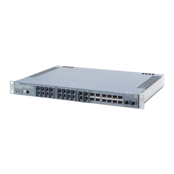
SIMATIC NET
Industrial Ethernet Switches
SCALANCE XR-300
Operating Instructions
03/2023
C79000-G8976-C586-02
Introduction
Safety notices
Security recommendations
Description of the device
Installing and removing
Connecting up
Maintenance and cleaning
Troubleshooting
Technical specifications
Dimension drawings
Approvals
1
2
3
4
5
6
7
8
9
10
11
Advertisement
Table of Contents

Related Manuals for Siemens SIMATIC NET SCALANCE XR-300


Summary of Contents for Siemens SIMATIC NET SCALANCE XR-300
- Page 1 Introduction Safety notices Security recommendations SIMATIC NET Description of the device Industrial Ethernet Switches SCALANCE XR-300 Installing and removing Connecting up Operating Instructions Maintenance and cleaning Troubleshooting Technical specifications Dimension drawings Approvals 03/2023 C79000-G8976-C586-02...
- Page 2 Note the following: WARNING Siemens products may only be used for the applications described in the catalog and in the relevant technical documentation. If products and components from other manufacturers are used, these must be recommended or approved by Siemens. Proper transport, storage, installation, assembly, commissioning, operation and maintenance are required to ensure that the products operate safely and without any problems.
-
Page 3: Table Of Contents
Table of contents Introduction ............................7 Purpose ..........................7 Scope of validity ........................7 Designations used........................ 7 Additional documentation ....................8 Service & Support ....................... 9 SIMATIC NET glossary......................9 Security information ......................10 Error/fault .......................... 10 Decommissioning ......................10 1.10 Recycling and disposal ....................... - Page 4 Table of contents 4.7.1 Position ..........................35 4.7.2 Port LEDs ........................... 35 4.7.3 "F" LED..........................37 4.7.4 LEDs "L1" and "L2" ......................37 4.7.5 "RM" LED..........................38 4.7.6 "SB" LED..........................38 4.7.7 LEDs "DM1" and "DM2"....................... 39 SELECT / SET button ......................39 4.8.1 Position ..........................
- Page 5 Table of contents Maintenance and cleaning ........................79 Troubleshooting........................... 81 Resetting the device to default settings with the button (in the startup phase)....81 Resetting the device to default settings with the button (during operation)......82 Load a firmware file via TFTP....................83 Technical specifications ........................
- Page 6 Table of contents SCALANCE XR-300 Operating Instructions, 03/2023, C79000-G8976-C586-02...
-
Page 7: Introduction
Introduction These operating instructions support you when installing and connecting up devices of the SCALANCE XR-300 product group. The configuration and the integration of the devices in a network are not described in these operating instructions. Purpose The SCALANCE XR-300/XR-300EEC switches are rack switches for installation in the 19" control cabinet. -
Page 8: Additional Documentation
The listed documents are the documents that were available at the time of the publication. Newer versions of these documents or the associated products may be available. Additional information is available in the SIOS or contact your Siemens customer service. Product notes... -
Page 9: Service & Support
Introduction 1.6 SIMATIC NET glossary Catalogs You will find the article numbers for the Siemens products of relevance here in the following catalogs: • SIMATIC NET Industrial Communication / Industrial Identification, catalog IK PI • SIMATIC Products for Totally Integrated Automation and Micro Automation, catalog ST 70 •... -
Page 10: Security Information
To stay informed about product updates, subscribe to the Siemens Industrial Security RSS Feed under https://www.siemens.com/cert (https://www.siemens.com/cert). Error/fault If a fault develops, send the device to your SIEMENS representative for repair. Repairs on-site are not permitted. Decommissioning Shut down the device properly to prevent unauthorized persons from accessing confidential data in the device memory. -
Page 11: Recycling And Disposal
2012/19/EU for the disposal of electrical and electronic equipment. Do not dispose of the products at public disposal sites. For environmentally friendly recycling and the disposal of your old device contact a certified disposal company for electronic scrap or your Siemens contact (Product return (https:// support.industry.siemens.com/cs/ww/en/view/109479891)). - Page 12 Introduction 1.12 Electrostatic discharge SCALANCE XR-300 Operating Instructions, 03/2023, C79000-G8976-C586-02...
-
Page 13: Safety Notices
Safety notices Read the safety notices Note the following safety notices. These relate to the entire working life of the device. You should also read the safety notices relating to handling in the individual sections, particularly in the sections "Installation" and "Connecting up". CAUTION To prevent injury and damage, read the manual before using the device. - Page 14 Safety notices SCALANCE XR-300 Operating Instructions, 03/2023, C79000-G8976-C586-02...
-
Page 15: Security Recommendations
OpenVPN). • Separate connections correctly (WBM, SSH etc.). • Check the user documentation of other Siemens products that are used together with the device for additional security recommendations. • Using remote logging, ensure that the system protocols are forwarded to a central logging server. - Page 16 Security recommendations 3.1 Security recommendations Authentication Note Accessibility risk - Risk of data loss Do not lose the passwords for the device. Access to the device can only be restored by resetting the device to factory settings which completely removes all configuration data. •...
- Page 17 • Verify certificates based on the fingerprint on the server and client side to prevent "man in the middle" attacks. Use a second, secure transmission path for this. • Before sending the device to Siemens for repair, replace the current certificates and keys with temporary disposable certificates and keys, which can be destroyed when the device is returned.
- Page 18 Security recommendations 3.1 Security recommendations • Ensure that the latest firmware version is installed, including all security-related patches. You can find the latest information on security patches for Siemens products at the Industrial Security (https://www.siemens.com/industrialsecurity) or ProductCERT Security Advisories (https://www.siemens.com/cert/en/cert-security-advisories.htm) website.
- Page 19 Security recommendations 3.1 Security recommendations Secure/non-secure protocols and services • Avoid or disable non-secure protocols and services, for example HTTP, Telnet and TFTP. For historical reasons, these protocols are available, however not intended for secure applications. Use non-secure protocols on the device with caution. •...
-
Page 20: Available Services
Security recommendations 3.2 Available services Available services The table includes the following columns: • Service/Protocol The protocols and services supported by the device. • Protocol / Port number The protocol used by the service / the port number assigned to the service •... - Page 21 Security recommendations 3.2 Available services Service/ Protocol/ Default port sta‐ Configurable Authentication Encryption Protocol Port number port Syslog UPD/514 Closed ✓ TCP/6514 TELNET TCP/23 Open ✓ TFTP UDP/69 Open ✓ Port number can be configured via the WBM. SCALANCE XR-300 Operating Instructions, 03/2023, C79000-G8976-C586-02...
- Page 22 Security recommendations 3.2 Available services SCALANCE XR-300 Operating Instructions, 03/2023, C79000-G8976-C586-02...
-
Page 23: Description Of The Device
Description of the device Article numbers Article numbers Device Properties Article number SCALANCE XR326-8 24 V AC/DC version 6GK5334-2TS00-2AR3 • 24 x 10 / 100 / 1000 Mbps RJ45 ports • 2 x 1 / 2.5 / 5 / 10 Gbps RJ45 ports •... - Page 24 Description of the device 4.1 Article numbers Device Properties Article number SCALANCE XR326-8EEC 6GK5334-2TS00-2ER3 • 24 x 10 / 100 / 1000 Mbps RJ45 ports • 2 x 1 / 2.5 / 5 / 10 Gbps RJ45 ports • 8 x SFP / SFP+ plug-in transceiver slots with 1 / 10 Gbps •...
- Page 25 Description of the device 4.1 Article numbers Factory settings: Industrial Ethernet profile • Industrial Ethernet protocol: PROFINET • Base Bridge Mode: 802.1Q VLAN Bridge • Redundancy mechanism: RSTP • Trust mode: Trust CoS-DSCP • IGMP Snooping/IGMP Querier: Off • IPv4 Address Collision Detection: Never give up SCALANCE XR-300 Operating Instructions, 03/2023, C79000-G8976-C586-02...
-
Page 26: Device Views
Description of the device 4.2 Device views Device views 4.2.1 SCALANCE XR326-8 24 V AC/DC The following figure shows an overview of the components of a 24 V AC/DC device version of the SCALANCE XR326-8. The SCALANCE XR326-8EEC device is identical in design except that it has conformal-coated PCBs. -
Page 27: Scalance Xr326-8 100
Description of the device 4.2 Device views 4.2.2 SCALANCE XR326-8 100 ... 240 VAC / 110 ... 250 VDC The following figure shows an overview of the components of a 100 to 240 VAC / 110 to 250 VDC device version of the SCALANCE XR326-8. ①... -
Page 28: Scalance Xr322-12 24 V Ac/Dc
Description of the device 4.2 Device views 4.2.3 SCALANCE XR322-12 24 V AC/DC The following figure shows an overview of the components of a 24 V AC/DC device version of the SCALANCE XR322-12. ① Electrical ports with 10/100/1000 Mbps ② Slots for SFP plug-in transceiver with 100/1000 Mbps ③... -
Page 29: Scalance Xr322-12 100 To 240 Vac / 110 To 250 Vdc
Description of the device 4.2 Device views 4.2.4 SCALANCE XR322-12 100 to 240 VAC / 110 to 250 VDC The following figure shows an overview of the components of a 100 to 240 VAC / 110 to 250 VDC device version of the SCALANCE XR322-12. ①... -
Page 30: Type Designation
Description of the device 4.4 Components of the product Type designation The type designation of a SCALANCE XR-300 is made up of several parts that have the following meaning: [ - ] Number of plug-in transceiver slots Number of electrical connectors Components of the product The following components are supplied with a SCALANCE XR-300: •... -
Page 31: Spare Parts
Description of the device 4.6 Accessories Unpacking and checking WARNING Do not use any parts that show evidence of damage If you use damaged parts, there is no guarantee that the device will function according to the specification. If you use damaged parts, this can lead to the following problems: •... -
Page 32: Serial Usb Cable
Description of the device 4.6 Accessories 4.6.2 Serial USB cable Component Description Article number Connecting cable Preassembled USB cable with USB Type A and USB 7ML1930-1FN Type B connector, length: 2 m (USB Type A / USB Type B) Pack of 1 4.6.3 Power cable Component Description Article number... -
Page 33: Sfp Transceivers
Description of the device 4.6 Accessories 4.6.5 SFP Transceivers Pluggable transceiver SFP (100 Mbps) Type Property Article number SFP991-1 1 x 100 Mbps, LC port optical for glass FO cable 6GK5 991-1AD00-8AA0 (multimode), up to max. 5 km 10 packing unit (VPE 10) 6GK5 991-1AD00-8AC0 SFP991-1 (C) 1 x 100 Mbps, SC port optical, for glass FO cable... - Page 34 Description of the device 4.6 Accessories Type Property Article number SFP992-1LH+ 1 x 1000 Mbps LC port optical for glass FO cable 6GK5 992-1AP00-8AA0 (single mode) up to max. 70 km SFP992-1ELH 1 x 1000 Mbps LC port optical for glass FO cable 6GK5 992-1AQ00-8AA0 (single mode) up to max.
-
Page 35: Led Display
Description of the device 4.7 LED display Can only be operated in SFP+ slots. Note Restriction for pluggable transceivers The maximum ambient temperature changes if you use pluggable transceivers: • If you use pluggable transceiver SFP993-1LH, the maximum ambient temperature is reduced to 50 ℃. - Page 36 Description of the device 4.7 LED display The meaning of the Port LEDs depends on the set display mode, see section "LEDs "DM1" and "DM2" (Page 39)". Meaning in display mode A In display mode A, the port LEDs indicate whether a valid link exists. LED color LED status Meaning...
-
Page 37: F" Led
Description of the device 4.7 LED display Meaning in display mode D In display mode D, the port LEDs indicate whether the port is monitored. LED color LED status Meaning Port is not monitored. Green Port is monitored for "Link up". Error handling is triggered when the port changes to the active status. -
Page 38: Rm" Led
Description of the device 4.7 LED display Meaning in display modes A, B, C and E In the display modes A, B, C and E, you can determine whether the power supply is connected by observing LEDs "L1" and "L2" . L1/L2 LED L1/L2 connector LED color... -
Page 39: Leds "Dm1" And "Dm2
Description of the device 4.8 SELECT / SET button 4.7.7 LEDs "DM1" and "DM2" The "DM1" and "DM2" LEDs indicate which display mode is set. There are 4 display modes (A, B, C and D). Display mode A is the default mode. Depending on the set display mode, the "L1", "L2"... -
Page 40: Setting The Display Mode
The CLP has a USB type C interface and can be used with the following devices that have a corresponding interface: • Siemens products • Personal computers (PCs), such as desktop PCs, tablet PCs, laptops, or smartphones SCALANCE XR-300... -
Page 41: Position
– The configuration data of the device is stored in a secured memory area of the CLP. This secured memory area can only be accessed via the authentication of the Siemens device. – The device checks whether a CLP is inserted at one second intervals. If the device detects that the CLP has been removed, it restarts automatically. - Page 42 Description of the device 4.9 Configuration License PLUG SCALANCE XR-300 Operating Instructions, 03/2023, C79000-G8976-C586-02...
-
Page 43: Installing And Removing
Installing and removing Safety during installation Safety notices When installing the device, keep to the safety notices listed below. NOTICE Improper mounting Improper mounting may damage the device or impair its operation. • Before mounting the device, always ensure that there is no visible damage to the device. •... - Page 44 Installing and removing 5.1 Safety during installation WARNING The device is intended for indoor use only. WARNING The device may only be operated in an environment of contamination class 1 or 2 (see EN/IEC 60664-1, GB/T 16935.1). WARNING When used in hazardous environments corresponding to Class I, Division 2 or Class I, Zone 2, the device must be installed in a cabinet or a suitable enclosure.
- Page 45 Installing and removing 5.1 Safety during installation WARNING Substitution of components may impair suitability for Division 2. WARNING EXPLOSION HAZARD For operation the device is intended to be installed within an enclosure/control cabinet. The inner temperature of the enclosure/control cabinet corresponds to the ambient temperature of the device.
-
Page 46: Types Of Installation
Installing and removing 5.2 Types of installation WARNING If the temperature at the cable or housing socket or at the branching points of the cables exceeds 60 °C, special precautions must be taken. If the equipment is operated at ambient temperatures in excess of 40 °C, only use cables with permitted operating temperature of at least 80 ℃. - Page 47 Installing and removing 5.2 Types of installation Note Installation of 100 to 240 V AC / 110 to 250 V DC devices The operation of 100 to 240 V AC / 110 to 250 V DC devices connected to the power supply via one or two DC terminal blocks is only permitted inside a control cabinet.
-
Page 48: 19" Rack Mounting
Installing and removing 5.3 19" rack mounting SFP transceivers Information about pulling and plugging SFP or SFP+ transceivers can be found in the section "Inserting and removing pluggable transceivers (Page 53)". 19" rack mounting Notes on 19" rack mounting WARNING Increased ambient temperature When installed in a closed rack or a rack unit with several devices, the ambient temperature of the rack may be higher than the room temperature. - Page 49 Installing and removing 5.3 19" rack mounting Note Mounting with two mounting brackets Mounting in a 19" rack is performed with two mounting brackets, which are pre-installed on the front of the rack unit. Alternatively, you can mount the rack unit in a 19" control cabinet from the rear. To do this, unscrew the two mounting brackets from the rack unit and attach them upside down to the two side panels at the rear of the unit.
-
Page 50: Four-Point Mounting
Installing and removing 5.4 Four-point mounting Uninstalling To remove the device from a 19" rack, follow the steps below: 1. Disconnect all connected cables. 2. Undo the securing screws on the mounting brackets 3. Remove the device from the 19" rack. NOTICE Rack-mount instructions A) Elevated Operating Ambient - If installed in a closed or multi-unit rack, the operating... - Page 51 Installing and removing 5.4 Four-point mounting Requirements For the four-point mounting, you require the following: • 4 suitable brackets • 4 recessed head screws (M3 x 6) per mounting bracket for fastening the mounting bracket to the device • 2 suitable half-round screws (6 mm diameter) per mounting bracket for fastening the mounting bracket to the base.
- Page 52 Installing and removing 5.4 Four-point mounting Procedure To install the device with a four-point mounting, follow the steps below: 1. Remove the mounting brackets for 19" rack installation, if necessary. To do so, loosen the 8 screws on each side and remove the mounting bracket. 2.
-
Page 53: Inserting And Removing Pluggable Transceivers
WARNING Use only approved SFP transceivers If you use SFP transceivers that have not been approved by Siemens AG, there is no guarantee that the device will function according to its specifications. If you use unapproved SFP transceivers, this can lead to the following problems: •... -
Page 54: Removing A Pluggable Transceiver (Sfp/Sfp+)
Installing and removing 5.6 Disassembly 5.5.3 Removing a pluggable transceiver (SFP/SFP+) Notes on deinstallation CAUTION Risk of burns due to the high temperatures of the pluggable transceiver The pluggable transceivers can be plugged and pulled during operation. Leave the transceiver to cool down. Procedure Follow the steps below to remove a pluggable transceiver: 1. -
Page 55: Connecting Up
Connecting up Safety when connecting up Safety notices When connecting up the device, keep to the safety notices listed below. If using power sources according to NEC Class 2 or PS2/LPS complying with UL 62368-1, please note the following information. WARNING Power supply The device is designed for operation with a directly connectable safety extra low voltage (SELV) - Page 56 Connecting up 6.1 Safety when connecting up Safety notices on use in hazardous areas General safety notices relating to protection against explosion WARNING Unsuitable cables or connectors Risk of explosion in hazardous areas • Only use connectors that meet the requirements of the relevant type of protection. •...
- Page 57 Connecting up 6.1 Safety when connecting up Notes for use in hazardous locations according to ATEX, IECEx, UKEX and CCC Ex If you use the device under ATEX, IECEx, UKEX or CCC Ex conditions you must also keep to the following safety instructions in addition to the general safety instructions for protection against explosion: WARNING Transient overvoltages...
- Page 58 Connecting up 6.1 Safety when connecting up Safety instructions for use in hazardous locations according to UL/FM HazLoc If you use the device under UL or FM HazLoc conditions, you must also adhere to the following safety instructions in addition to the general safety instructions for protection against explosion: WARNING EXPLOSION HAZARD...
-
Page 59: Wiring Rules
Connecting up 6.2 Wiring rules Further notes WARNING Safety notice for connecting with a LAN ID (Local Area Network) A LAN or LAN segment with all the interconnected devices should be contained completely in a single low voltage power distribution in a building. The LAN is designed either for “Environment A”... -
Page 60: Ac/Dc Power Supply
Connecting up 6.3 24 V AC/DC power supply 24 V AC/DC power supply Safety extra low voltage WARNING Power supply The equipment is designed for operation with a directly connectable safety extra low voltage (SELV) or with a power supply unit that meets the requirements ES1/SELV and PS2/LPS according to IEC/UL 62368-1. - Page 61 Connecting up 6.3 24 V AC/DC power supply NOTICE Suitable fuse for the power supply cables (corresponds to "Limited Energy") The current on the terminal may not exceed 3 A. Use a fuse for the power supply that is suitable for protection of AC/DC power supply circuits * and protects against currents >...
- Page 62 Connecting up 6.3 24 V AC/DC power supply Notes on the power supply WARNING Incorrect power supply The power supply unit for supplying the devices must comply with NEC Class 2 or PS2/LPS according to UL 62368-1: • Voltage range 19.2 - 31.2 V for DC and 19.2 - 30.0 V for AC (50 / 60 Hz) •...
- Page 63 Connecting up 6.3 24 V AC/DC power supply WARNING Operation only with safety extra-low voltage The device is designed for operation with a directly connectable safety extra-low voltage (SELV). (This does not apply to 100 to 240 VAC / 110 to 250 VDC devices). • Do not operate the device with an AC voltage higher than 30 V AC or a DC voltage higher than 31.2 V DC.
-
Page 64: Power Supply 100 To 240 Vac / 110 To 250 Vdc
Connecting up 6.4 Power supply 100 to 240 VAC / 110 to 250 VDC Power supply 100 to 240 VAC / 110 to 250 VDC Notes on the power supply WARNING Danger from line voltage The supply voltage for the devices listed is 100 to 240 V AC / 110 to 250 V DC. This device can only function correctly and safely if it is transported, stored, set up, and installed correctly, and operated and maintained as recommended. - Page 65 Connecting up 6.4 Power supply 100 to 240 VAC / 110 to 250 VDC IEC plug ① When shipped, the connection for the 3-pin IEC plug is available. The device is grounded via the power cable. To connect the power supply, use the power cable listed in the section "Accessories (Page 31)".
- Page 66 Connecting up 6.4 Power supply 100 to 240 VAC / 110 to 250 VDC DC terminal block ① When shipped, the connection for the 2-pin DC terminal block is covered. The DC terminal ④ block ships with the device. Protective grounding is provided by the grounding bolt You can recognize the type of power supply from the labeling on the device and the labeling of the terminal block for the power supply of the switch.
-
Page 67: Grounding
Connecting up 6.5 Grounding To use the DC terminal block, follow these steps: ② 1. Slide the cover to the right. ③ In this position, you cannot tighten the screw . The screw is captive and stays connected to the cover. ①... -
Page 68: Functional Ground
Connecting up 6.5 Grounding ① Grounding bolt Figure 6-6 Position of the grounding bolt on the rear of the device using a redundant 100 to 240 V AC / 110 to 250 V DC device version as an example 6.5.1 Functional ground EMC disturbances are diverted to ground via the functional ground. This ensures the immunity of the data transmission. -
Page 69: Protective Grounding (100 To 240 Vac / 110 To 250 Vdc Device Versions)
Connecting up 6.5 Grounding Requirements for protective grounding To wire a permanently connected protective grounding, use copper cables with a cross-section of ≥ 2.5 mm if the cables are mechanically protected. If the cables are not mechanically protected, use cables with a cross-section of 4.0 mm 6.5.3 Protective grounding (100 to 240 VAC / 110 to 250 VDC device versions) The connection of the reference potential surface with the protective conductor system is... -
Page 70: Connecting The Grounding Via A Grounding Bolt
Connecting up 6.6 Industrial Ethernet 6.5.4 Connecting the grounding via a grounding bolt ① Toothed washer ② Grounding bolt ③ Grounding terminal with cable ④ Washer ⑤ Spring washer ⑥ To connect the functional or protective grounding on devices with a screw-in grounding bolt, follow these steps: ①... - Page 71 Connecting up 6.6 Industrial Ethernet Pin assignment The following table shows the pin assignment of the RJ45 connectors. Pin number Assignments for ports up to RJ45 connector Max. 100 Mbps Max. 1000 Mbps Max. 10000 Mbps Pin 1 Pin 2 Pin 3 Pin 4 n.
- Page 72 Connecting up 6.6 Industrial Ethernet Two components connected to a link segment can exchange information about the transfer and can adapt their settings to each other. The mode with the highest possible speed is set. Note • If a port is set permanently to full duplex, the connected partner port must also be set to full duplex.
-
Page 73: Optical
Connecting up 6.6 Industrial Ethernet 6.6.2 Optical NOTICE Failure of the data traffic due to contamination of optical plug-in connections Optical sockets and plugs are sensitive to contamination of the end face. Contamination can lead to the failure of the optical transmission network. Take the following precautions to avoid functional impairments: •... -
Page 74: Dependency Between Ports And Ambient Temperature (Derating)
Connecting up 6.6 Industrial Ethernet 6.6.3 Dependency between ports and ambient temperature (derating) The following figure shows the maximum number of ports or SFP transceivers that you can use so that the maximum ambient temperature specified in the left-hand column is permissible. -40 °C ... -
Page 75: Signaling Contact
Connecting up 6.7 Signaling contact The table below shows the assignment of the SFP transceivers to the specified groups. Category Group Type Article number Group 1 SFP991-1 6GK5 991-1AD00-8AA0 SFP991-1 (C) 6GK5 991-1AD00-8FA0 SFP991-1LD 6GK5 991-1AF00-8AA0 SFP992-1 6GK5 992-1AL00-8AA0 SFP992-1LD 6GK5 992-1AM00-8AA0 SFP992-1LD (C) 6GK5 992-1AM00-8FA0 Group 2... - Page 76 Connecting up 6.7 Signaling contact • Note the wiring rules (Page 59). • The signaling contact can be controlled manually via the user interfaces. Information on this can be found in the Configuration manuals (Page 8). WARNING Risk of electric shock and property damage due to voltage being too high The signaling contact can be operated in the voltage range of 19.2 to 31.2 V DC or 19.2 to 30.0 V AC and subjected to a maximum load of 100 mA.
-
Page 77: Usb Console Interface
"Accessories (Page 31)". Driver for the USB console interface To use the USB console interface under Windows, you must download and install the following driver: Drivers (https://support.industry.siemens.com/cs/ww/en/ps/6GK5998-3GS00-2AC2/dl). Position The interface is located on the front of the device. -
Page 78: Replacing A Clp
Connecting up 6.9 Replacing a CLP Replacing a CLP To use the CLP correctly, note the structure of the CLP: ① Square edges ② Front edge of the CLP ③ Round edges Removing a CLP To remove a CLP from the device, follow the steps below: 1. -
Page 79: Maintenance And Cleaning
Maintenance and cleaning WARNING Unauthorized repair of devices in explosion-proof design Risk of explosion in hazardous areas • Repair work may only be performed by personnel authorized by Siemens. WARNING Impermissible accessories and spare parts Risk of explosion in hazardous areas •... - Page 80 Maintenance and cleaning SCALANCE XR-300 Operating Instructions, 03/2023, C79000-G8976-C586-02...
-
Page 81: Troubleshooting
Troubleshooting Resetting the device to default settings with the button (in the startup phase) NOTICE Connection hazard - risk of communication failure Depending on the configuration of your network, a reset device can cause circular frames and thus the loss of data traffic. NOTICE Configuration hazard - risk of data loss If a CLP is inserted in the device, the CLP is also reset to default settings. -
Page 82: Resetting The Device To Default Settings With The Button (During Operation)
Troubleshooting 8.2 Resetting the device to default settings with the button (during operation) Resetting the device to factory defaults To reset the device to the factory defaults during the startup phase, follow the steps below: 1. Turn off the power to the device. 2. -
Page 83: Load A Firmware File Via Tftp
The device restarts with default settings. Load a firmware file via TFTP. Firmware The firmware is signed and encrypted. This ensures that only firmware created by Siemens can be downloaded to the device. Procedure with Microsoft Windows You can download new firmware to the device using TFTP. To do this, the device does not need to be reachable either using Web Based Management (WBM) or using the Command Line Interface (CLI). - Page 84 Troubleshooting 8.3 Load a firmware file via TFTP. 6. Assign an IP address to the device using DHCP or SINEC PNI. 7. In a Windows command prompt, go to the directory where the file with the new firmware is located and use the following command: tftp -i <IP address>...
-
Page 85: Technical Specifications
Spring-loaded terminal block, 2-pin Permitted voltage range 24 V DC Load rating Max. 100 mA Button Quantity Configuration interface Removable data storage medium Quantity Product name Siemens Configuration and License PLUG (CLP) Connection to power supply SCALANCE XR-300 Operating Instructions, 03/2023, C79000-G8976-C586-02... - Page 86 Technical specifications 9.1 SCALANCE XR326-8 and SCALANCE XR326-8EEC Technical specifications Power supply Design Spring-loaded terminal block, 2-pin Rated voltage 24 V AC / 24 V DC Voltage range 19.2 to 30.0 V AC 19.2 to 31.2 V DC Frequency 50 / 60 Hz (with AC) Frequency range 50 Hz to 60 Hz Fusing 10 A / 250 V Properties...
- Page 87 Technical specifications 9.1 SCALANCE XR326-8 and SCALANCE XR326-8EEC Technical specifications Ambient temperature Property Startup at -40 °C With LAN operation with RJ45 plug During operation in horizontal installation position: Up to 2000 m above sea level -40 to +70 °C When operating with plug-in trans‐ During operation in horizontal installation position: ceivers of the types: -40 °C to +60 °C...
-
Page 88: 100 To 240 Vac / 110 To 250 Vdc Device Version
Technical specifications 9.1 SCALANCE XR326-8 and SCALANCE XR326-8EEC Technical specifications Conformal coating of the PCBs SCALANCE XR326-8 SCALANCE XR326-8 EEC Design of the mounting bracket for four-point mounting Dimensions (W x H x D) 43.6 x 43.6 x 18.3 mm (1 height unit) Plate thickness 1.5 mm Bending radii... - Page 89 24 V DC Load rating Max. 100 mA Button Quantity Configuration interface Removable data storage medium Quantity Product name Siemens Configuration and License PLUG (CLP) Connection to power supply Power supply Design IEC plug C14 (AC) DC terminal block, 2-pin (DC) Rated voltage 100 to 240 V AC...
- Page 90 Technical specifications 9.1 SCALANCE XR326-8 and SCALANCE XR326-8EEC Technical specifications Ambient temperature Property Startup at -25 °C With LAN operation with RJ45 plug During operation in horizontal installation position: Up to 2000 m above sea level -25 °C to +60 °C When operating with plug-in trans‐ During operation in horizontal installation position: ceivers of the types: -25 °C to +60 °C...
- Page 91 Technical specifications 9.1 SCALANCE XR326-8 and SCALANCE XR326-8EEC Technical specifications Design of the mounting bracket for four-point mounting Dimensions (W x H x D) 43.6 x 43.6 x 18.3 mm (1 height unit) Plate thickness 1.5 mm Bending radii 1.5 mm Surface of the housing Stainless steel X6CR17 Mean time between failure (MTBF) MTBF (EN/IEC 61709;...
-
Page 92: Scalance Xr322-12
Load rating Max. 100 mA Button Quantity Configuration interface Removable data storage medium Quantity Product name Siemens Configuration and License PLUG (CLP) Connection to power supply Power supply Design Spring-loaded terminal block, 2-pin Rated voltage 24 V AC / 24 V DC Voltage range 19.2 to 30.0 V AC... - Page 93 Technical specifications 9.2 SCALANCE XR322-12 Technical specifications Current consumption Rated voltage 3 A Effective power loss Rated voltage 72 W Cable cross-section Minimum 0.75 mm^2 (AWG 18) Maximum 2.5 mm^2 (AWG 12) Permitted ambient conditions Ambient temperature Property Startup at -40 °C With LAN operation with RJ45 plug During operation in horizontal installation position: Up to 2000 m above sea level -40 to +70 °C...
- Page 94 Technical specifications 9.2 SCALANCE XR322-12 Technical specifications Dimensions (W x H x D) 446 x 43.5 x 374.8 mm (1 height unit) Weight 8000 g Installation options • 19" rack mounting • Four-point mounting Mounting restriction None Conformal coating of the PCBs Design of the mounting bracket for four-point mounting Dimensions (W x H x D) 43.6 x 43.6 x 18.3 mm (1 height unit)
-
Page 95: 100 To 240 Vac / 110 To 250 Vdc Device Version
24 V DC Load rating Max. 100 mA Button Quantity Configuration interface Removable data storage medium Quantity Product name Siemens Configuration and License PLUG (CLP) Connection to power supply Power supply Design IEC plug C14 (AC) DC terminal block, 2-pin (DC) Rated voltage 100 to 240 V AC... - Page 96 Technical specifications 9.2 SCALANCE XR322-12 Technical specifications Permitted ambient conditions Ambient temperature Property Startup at -25 °C With LAN operation with RJ45 plug During operation in horizontal installation position: Up to 2000 m above sea level -25 °C to +60 °C When operating with plug-in trans‐ During operation in horizontal installation position: ceivers of the types: -25 °C to +60 °C...
-
Page 97: Mechanical Stability (In Operation)
Technical specifications 9.3 Mechanical stability (in operation) Technical specifications Mounting restriction Operation with a DC terminal block only within a control cabinet Conformal coating of the PCBs Design of the mounting bracket for four-point mounting Dimensions (W x H x D) 43.6 x 43.6 x 18.3 mm (1 height unit) Plate thickness 1.5 mm... -
Page 98: Cable Lengths
Technical specifications 9.5 Switching properties Cable lengths The cable lengths listed below apply to the devices named in the scope of validity: Cable Permitted cable length IE TP torsion cable 0 to 45 m with IE FC Outlet RJ-45 + 10 m TP cord + 10 m TP cord IE TP torsion cable 0 to 55 m with IE FC RJ-45 Plug 180... - Page 99 Technical specifications 9.5 Switching properties Note The number of devices connected in a line, which are named in the scope of validity, influences the frame delay. When a frame passes through an IE switch, it is delayed by the store-and- forward function of the device: •...
- Page 100 Technical specifications 9.5 Switching properties SCALANCE XR-300 Operating Instructions, 03/2023, C79000-G8976-C586-02...
-
Page 101: Dimension Drawings
Dimension drawings 10.1 Dimension drawings SCALANCE XR-300 Note Dimensions are specified in mm. Front view Figure 10-1 Width and height based using the example of a 24 V AC/DC device version Top view of the 24 V AC/DC device versions Figure 10-2 Depth SCALANCE XR-300 Operating Instructions, 03/2023, C79000-G8976-C586-02... -
Page 102: Mounting Brackets For Use On Ships
Dimension drawings 10.2 Mounting brackets for use on ships Top view of the 100 to 240 VAC / 110 to 250 VDC device versions Figure 10-3 Depth 10.2 Mounting brackets for use on ships You need special mounting brackets to install the device horizontally on a ship. Below you will find the design drawing for making the mounting brackets. - Page 103 Dimension drawings 10.2 Mounting brackets for use on ships Mounting bracket for four-point mounting Dimensions are specified in mm. Figure 10-4 View from the front, top, and side SCALANCE XR-300 Operating Instructions, 03/2023, C79000-G8976-C586-02...
- Page 104 Dimension drawings 10.2 Mounting brackets for use on ships SCALANCE XR-300 Operating Instructions, 03/2023, C79000-G8976-C586-02...
-
Page 105: Approvals
Current approvals on the Internet You will find the current approvals for the product on the Internet pages of Siemens Industry Online Support (https://support.industry.siemens.com/cs/ww/en/ps/15273/cert). Notes for the manufacturers of machines This product is not a machine in the sense of the EC Machinery Directive or the Supply of Machinery (Safety) Regulations (UK). - Page 106 EC L174, 01/07/2011, p. 88-110 You will find the EC declaration of conformity for these products on the Internet pages of Siemens Industry Online Support (https://support.industry.siemens.com/cs/ww/en/ps/15273/ cert).
- Page 107 "SIMATIC NET Product Information Use of subassemblies/modules in a Zone 2 Hazardous Area". You will find this document • on the data medium that ships with some devices. • on the Internet pages under Siemens Industry Online Support (https:// support.industry.siemens.com/cs/ww/en/view/78381013).
- Page 108 Approvals The products meet the requirements of the following standards: • EN/IEC 60079-7, GB 3836.8 • EN IEC/IEC 60079-0, GB 3836.1 You will find the current versions of the standards in the currently valid certificates. Note Only variants with 24 V AC / 24 V DC power supply meet the requirements of this approval. Note for devices with CLASS 1 LASER Important note on products certified according to Type Examination Certificate KEMA 07ATEX0145 X as of Issue 95 / DEKRA 18ATEX0025 X and IECEx Certificate of Conformity DEK...
- Page 109 Approvals Applied standards: • EN 61000‑6‑2 Electromagnetic compatibility (EMC) - Part 6-2: Generic standards - Immunity for industrial environments • EN 61000‑6‑4 Electromagnetic compatibility (EMC) - Part 6-4: Generic standards - Emission standard for industrial environments You will find the current versions of the standards in the currently valid EC/UK Declaration of Conformity.
- Page 110 Approvals Underwriters Laboratories Inc. complying with • UL 62368-1 (information/communication technology) • CSA C22.2 No. 62368-1 (information/communication technology) Report no. E115352 Note Only variants with 24 V AC / 24 V DC power supply meet the requirements of this approval. cULus Approval for Information Technology Equipment cULus Recognized Approval only I.
- Page 111 Approvals Applied standards: • AS/NZS CISPR11 (Industrial, scientific and medical equipment - Radio-frequency disturbance characteristics - Limits and methods of measurement). • EN 61000-6-4 Electromagnetic compatibility (EMC) - Part 6-4: Generic standards - Emission standard for industrial environments You will find the current versions of the standards in the currently valid RCM SDoCs (Self- Declaration of Conformity).
- Page 112 • "Industrial Ethernet / PROFINET Industrial Ethernet" System Manual (https:// support.industry.siemens.com/cs/ww/en/view/27069465) • "Industrial Ethernet / PROFINET - Passive Network Components" System Manual (https:// support.industry.siemens.com/cs/ww/en/view/84922825) • "EMC Installation Guidelines" configuration manual (https:// support.industry.siemens.com/cs/ww/en/view/60612658)
-
Page 113: Index
Index ESD directives, 11 19" rack mounting, 26, 27, 28, 29, 49 Factory settings, 82 Fault LED, 26, 27, 28, 29 Fault/error status, 37 Firmware, 37 Accessories, 31 Four-point mounting, 49, 50 Approvals, 105 Functional ground, 67 Article numbers, 23 Autonegotiation, 71 AWG, 59 Grounding, 67 Bracket, 26, 27, 28, 29 Housing, 87, 90, 93, 96 Cable cross section, 59 CE mark, 105 Clip, 53... - Page 114 Index SFP+ transceiver, 34 Ship, 50 Signaling contact, 26, 27, 28, 29, 37, 75 Slot, 53 Operating mode, 36 Spare parts, 31 Overvoltage protection, 62 Spring-loaded terminal, 75 Startup phase, 37, 81 System manual, 46, 112 Permitted ambient conditions, 86, 89, 93, 96 Pin assignment, 71 PLUG, 32 Transmission speed, 36 Pluggable transceiver Type designation, 30 Inserting, 53 Type of installation, 46 Notes on deinstallation, 54...