
Related Manuals for Siemens SIMATIC NET RUGGEDCOM RS416P


Summary of Contents for Siemens SIMATIC NET RUGGEDCOM RS416P
- Page 1 Edition 11/2022 Installation Manual SIMATIC NET Rugged Ethernet Switches RUGGEDCOM RS416P https://www.siemens.com/ruggedcom...
- Page 2 Preface Introduction Installing Device SIMATIC NET Device Management Rugged Ethernet Switches RUGGEDCOM RS416P Communication Ports Technical Specifications Installation Manual Certification 11/2022 C79000-G8976-1019-11...
- Page 3 Note the following: WARNING Siemens products may only be used for the applications described in the catalog and in the relevant technical documentation. If products and components from other manufacturers are used, these must be recommended or approved by Siemens. Proper transport, storage, installation, assembly, commissioning, operation and maintenance are required to ensure that the products operate safely and without any problems.
-
Page 4: Table Of Contents
Accessing Documentation ....................... v Registered Trademarks ......................v Warranty ..........................vi Training ..........................vi Customer Support ........................vi Contacting Siemens ....................... vii Introduction ........................... 1 Feature Highlights ....................1 Description ......................2 Required Tools and Materials ................. 4 Decommissioning and Disposal ................4 Cabling Recommendations .................. - Page 5 Table of Contents Copper Ethernet Ports ..................23 PoE Ports ......................24 Fiber Optic Ethernet Ports ................... 25 Serial Ports ......................26 BNC Ports ......................29 Connecting Multiple RS485 Devices ..............30 Technical Specifications ...................... 33 Power Supply Specifications ................33 PoE Power Supply Specifications ................
-
Page 6: Preface
SIMATIC NET Glossary The SIMATIC NET Glossary describes special terms that may be used in this document. The glossary is available online via Siemens Industry Online Support (SIOS) at: https://support.industry.siemens.com/cs/ww/en/view/50305045 Accessing Documentation The latest user documentation for RUGGEDCOM RS416P is available online at https:// support.industry.siemens.com. -
Page 7: Warranty
Preface Warranty Warranty Siemens warrants this product for a period of five (5) years from the date of purchase, conditional upon the return to factory for maintenance during the warranty term. This product contains no user-serviceable parts. Attempted service by unauthorized personnel shall render all warranties null and void. -
Page 8: Contacting Siemens
Call a local hotline center to submit a Support Request (SR). To locate a local hotline center, visit https://w3.siemens.com/aspa_app/?lang=en. Mobile App Install the Industry Online Support app by Siemens AG on any Android, Apple iOS or Windows mobile device and be able to: •... - Page 9 Preface Contacting Siemens viii RUGGEDCOM RS416P Installation Manual, 11/2022, C79000-G8976-1019-11...
-
Page 10: Introduction
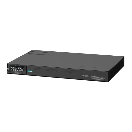
Introduction The RUGGEDCOM RS416P is an industrially hardened serial device server with an integrated, fully managed, 4-Port Power over Ethernet (PoE) switch, designed to operate reliably in electrically harsh and climatically demanding utility substation and industrial environments. Featuring a modular design that can support up to 16 serial ports, the RUGGEDCOM RS416P is able to interconnect multiple types of intelligent electronic devices (IEDs) that have different methods of communications. -
Page 11: Description
Introduction 1.2 Description • Converts DNP3.0 to DNP over UDP/TCP Power Over Ethernet (PoE) • Two or four 10/100Base-TX 802.3af compliant ports • Data and power over a single Ethernet cable • Powered from the internal 48 VDC source • No mid-span patch panel required •... - Page 12 Introduction 1.2 Description Serial Ports Fiber Optic Ethernet and/or BNC (Optional) Ports Port Status Indicator LEDs Display Mode Indicator LEDs Mode Button Alarm Indicator LED Power Module Indicator LEDs RS-232 Serial Console Port (RJ45) Figure 1.1 RUGGEDCOM RS416P Communication Ports Ports for communicating with other devices or accessing the RUGGEDCOM RS416P operating system are described in "Communication Ports"...
-
Page 13: Required Tools And Materials
Introduction 1.3 Required Tools and Materials Power Module Indicator LEDs The power module indicator LEDs indicate the status of the power modules. Color Description Green The power supply is supplying power Power supply failure No power supply is installed RS-232 Console Port The serial console port is for interfacing directly with the device and accessing initial management functions. -
Page 14: Cabling Recommendations
Siemens also does not recommend using copper Ethernet ports to interface with devices in the field across distances that could produce high levels of ground potential rise (i.e. greater than 2500 V), during line-to-ground fault conditions. -
Page 15: 1.6.1 Supported Time Synchronization Sources
Introduction 1.6.1 Supported Time Synchronization Sources TTL OUT Port TTL IN Port Figure 1.2 PTP Module For more information about the BNC ports, refer to "BNC Ports" (Page 29). 1.6.1 Supported Time Synchronization Sources The following time synchronization sources are supported by the RUGGEDCOM RS416P, with or without the PTP card: Synchronization Source Without PTP Card... -
Page 16: Ttl Outputs
Introduction 1.6.2 TTL Outputs Every Ethernet port on the RUGGEDCOM RS416P supports IEEE 1588. For more information, refer to "IEEE 1588 Support" (Page 1.6.2 TTL Outputs The PTP card provides a TTL (Transistor-Transistor Logic) output. The TTL OUT port supports the IRIG-B PWM and PPS signal formats. Enabling/ disabling the output port and selecting the signal format is controlled through the RUGGEDCOM RS416P operating system. - Page 17 Introduction 1.6.3 IEEE 1588 Support • Peer-to-Peer Slave Clock • Peer-to-Peer Master Clock RUGGEDCOM RS416P Installation Manual, 11/2022, C79000-G8976-1019-11...
-
Page 18: Installing Device
This product contains no user-serviceable parts. Attempted service by unauthorized personnel shall render all warranties null and void. Changes or modifications not expressly approved by Siemens Canada Ltd. could invalidate specifications, test results, and agency approvals, and void the user's authority to operate the equipment. -
Page 19: General Procedure
Visually inspect each item in the package for any physical damage. Verify all items are included. Note If any item is missing or damaged, contact Siemens for assistance. Mounting the Device The RUGGEDCOM RS416P is designed for maximum mounting and display flexibility. -
Page 20: 2.3.1 Mounting The Device To A Rack
Installing Device 2.3.1 Mounting the Device to a Rack NOTICE Heat generated by the device is channeled outwards from the enclosure. As such, it is recommended that 2.5 cm (1 in) of space be maintained on all open sides of the device to allow for some convectional airflow. -
Page 21: 2.3.2 Mounting The Device On A Din Rail
Installing Device 2.3.2 Mounting the Device on a DIN Rail If required, install adapters on the opposite side of the device to protect from vibrations. Insert the device into the rack. Note Since heat within the device is channelled to the enclosure, it is recommended that 1 rack-unit of space, or 44 mm (1.75 in), be kept empty above the device. -
Page 22: 2.3.3 Mounting The Device To A Panel
Installing Device 2.3.3 Mounting the Device to a Panel 2.3.3 Mounting the Device to a Panel For panel installations, the RUGGEDCOM RS416P can be equipped with panel/DIN rail adapters pre-installed on each side of the chassis. The adapters allow the device to be attached to a panel using screws. -
Page 23: Grounding The Device
Installing Device 2.5 Grounding the Device Note Control of the failsafe relay output is configurable through RUGGEDCOM RS416P. One common application for this relay is to signal an alarm if a power failure occurs. For more information, refer to the "RUGGEDCOM RS416P User Guide" for the RUGGEDCOM RS416P. -
Page 24: Connecting Power
Installing Device 2.6 Connecting Power #6 Ring Lug Figure 2.5 Chassis Ground Connection Connecting Power The RUGGEDCOM RS416P supports a single high AC or low DC power supply, and a separate 48 VDC power supply for PoE ports. The RUGGEDCOM RS416P can be equipped with either a screw-type or pluggable terminal block, which provides power to the AC/DC power module and PoE ports. - Page 25 Installing Device 2.6.1 Connecting AC or DC Power NOTICE Electrical hazard – risk of damage to equipment Do not connect AC power cables to a DC power supply terminal block. Damage to the power supply may occur. Note Terminals 5 and 7 (POWER 2) are reserved for the external PoE power supply. For information about connecting the external PoE power supply, refer to "Connecting External PoE Power"...
-
Page 26: 2.6.2 Connecting External Poe Power
For IEC 61850 compliance, use an IEC 61850 compliant PoE power supply with power cabling no longer than 3 m (118 in). Otherwise, Siemens recommends using the RUGGEDCOM RPS1300 switch-mode AC power supply. For more information about this power supply, refer to https:// support.industry.siemens.com/cs/ww/en/view/109478699. -
Page 27: 2.6.3 Wiring Examples
Installing Device 2.6.3 Wiring Examples Screw-Type Terminal Block Pluggable Terminal Block Jumper Terminal 4 (Chassis Ground) Terminal 5 (+/L) Terminal 7 (-/N) Chassis Ground Terminal Figure 2.7 Terminal Block Wiring Connect the negative wire from the power source to terminal 7 (-/N) on the terminal block. - Page 28 Installing Device 2.6.3 Wiring Examples Figure 2.8 Single AC Power Supply Figure 2.9 Single DC Power Supply RUGGEDCOM RS416P Installation Manual, 11/2022, C79000-G8976-1019-11...
- Page 29 Installing Device 2.6.3 Wiring Examples Figure 2.10 DC Power Supply and External PoE Power Supply Figure 2.11 AC Power Supply and External PoE Power Supply RUGGEDCOM RS416P Installation Manual, 11/2022, C79000-G8976-1019-11...
-
Page 30: Device Management
Device Management This section describes how to connect to and manage the device. Connecting to the Device The following describes the various methods for accessing the RUGGEDCOM RS416P console and Web interfaces on the device. For more detailed instructions, refer to the "RUGGEDCOM RS416P User Guide"... -
Page 31: Configuring The Device
Device Management 3.2 Configuring the Device Communication Ports Connect any of the available Ethernet ports on the device to a management switch and access the RUGGEDCOM RS416P console and Web interfaces via the device's IP address. For more information about available ports, refer to "Communication Ports"... -
Page 32: Communication Ports
Communication Ports The RUGGEDCOM RS416P can be equipped with various types of communication ports to enhance its abilities and performance. Each communication port type has a specific place in the RUGGEDCOM RS416P chassis. Slot 1 Slot 2 Slot 3 Slot 4 Slot 5 Slot 6 Figure 4.1... -
Page 33: Poe Ports
Communication Ports 4.2 PoE Ports WARNING Electric shock hazard – risk of serious personal injury and/or equipment interference If shielded cables are used, make sure the shielded cables do not form a ground loop via the shield wire and the RJ45 receptacles at either end. Ground loops can cause excessive noise and interference, but more importantly, create a potential shock hazard that can result in serious injury. -
Page 34: Fiber Optic Ethernet Ports
Communication Ports 4.3 Fiber Optic Ethernet Ports The total allowable power budget for all ports is 60 W. If the external power supply is less than 60 W, to prevent exceeding the power budget, port priorities can be set via the RUGGEDCOM RS416P operating system to disable low priority ports when demand is too high. -
Page 35: Serial Ports
Communication Ports 4.4 Serial Ports (Straight Tip) connectors. Make sure the Transmit (Tx) and Receive (Rx) connections of each port are properly connected and matched to establish a proper link. Tx Connector Tx Connector Rx Connector Rx Connector Figure 4.5 LC Port Figure 4.4 MTRJ Port ... - Page 36 Communication Ports 4.4 Serial Ports State Description No link detected For specifications on serial ports, refer to "Serial Port Specifications" (Page 35). The following is the pin-out description for ST, DB9 and RJ45 serial ports: Fiber Serial Port Tx Connector Rx Connector Figure 4.8 ST Port Serial DB9 Port...
- Page 37 Communication Ports 4.4 Serial Ports Serial DB9 Port with IRIG-B Support Mode RS232 DTE RS485 RS422 TX/RX+ IRIG-B+ Common (Isolated) Ground Common (Isolated) Ground TX/RX- Figure 4.10 Serial DB9 Port Pin Configuration Common (Isolated) Ground Shield Chassis Ground In RS232 DTE mode, ports transmit to DTE devices on pin 2 and receive from DTE on pin 3.
-
Page 38: Bnc Ports
Communication Ports 4.5 BNC Ports Serial RJ45 Port with IRIG-B Support RS232 RS485 RS422 Mode Mode Mode +IRIG-B Common (Isolated) Ground Figure 4.12 Serial RJ45 Port Pin Common (Isolated) Ground Configuration TX/RX+ TX/RX- Shield Chassis Ground In RS232 mode, the RJ45 ports conform to EIA-561 DTE, which transmit on TXD and receive on RXD. -
Page 39: Connecting Multiple Rs485 Devices
Communication Ports 4.6 Connecting Multiple RS485 Devices • Red – Error • Off – No signal detected Connecting Multiple RS485 Devices Each RS485 port can communicate with multiple RS485 devices by wiring devices together in sequence over a single twisted pair with transmit and receive signals on the same two wires (half duplex). - Page 40 Communication Ports 4.6 Connecting Multiple RS485 Devices RS485 Devices (32 Total) Figure 4.14 Recommended RS485 Wiring RUGGEDCOM RS416P Installation Manual, 11/2022, C79000-G8976-1019-11...
- Page 41 Communication Ports 4.6 Connecting Multiple RS485 Devices RUGGEDCOM RS416P Installation Manual, 11/2022, C79000-G8976-1019-11...
-
Page 42: Technical Specifications
Technical Specifications This section provides important technical specifications related to the device and available modules. Power Supply Specifications Note For specifications on the PoE power supply, refer to "PoE Power Supply Specifications" (Page 33). Input Range Maximum Power Internal Fuse Isolation Power Supply Type... -
Page 43: Copper Ethernet Port Specifications
Technical Specifications 5.4 Copper Ethernet Port Specifications Maximum Switching Voltage Rated Switching Current 80 VDC Copper Ethernet Port Specifications The following details the specifications for copper Ethernet ports that can be ordered with the RUGGEDCOM RS416P. Speed 10/100Base-TX Connector RJ45 Duplex FDX/HDX Cable Type >... -
Page 44: Serial Port Specifications
Technical Specifications 5.6 Serial Port Specifications Power Connector Cable Tx λ Tx Min. Tx Max. Distance Mode Sensitivity Saturation Budget Type Type (μm) (nm) (dBm) (dBm) (km) (dBm) (dBm) (dB) 62.5/125 1300 50/125 -22.5 62.5/125 MTRJ 1300 50/125 -22.5 9/125 1300 9/125 1300 9/125... -
Page 45: Irig-B Port Specifications
Technical Specifications 5.7 IRIG-B Port Specifications IRIG-B Port Specifications IRIG-B PWM Input Specifications Parameter Specification Input Voltage TTL-Compatible Input Impedance > 200 kΩ IRIG-B PWM Output Specifications Parameter Specification Output Current (I 100 mA Output Voltage (V TTL-Compatible Output Impedance (R 50 Ω... - Page 46 Technical Specifications 5.10 Dimension Drawings 438.15 Figure 5.1 Overall Dimensions RUGGEDCOM RS416P Installation Manual, 11/2022, C79000-G8976-1019-11...
- Page 47 Technical Specifications 5.10 Dimension Drawings 479.30 11.68 461.01 21.08 32.64 4.57 Figure 5.2 Rack Mount Dimensions 486.4 476.3 10.4 11.7 Figure 5.3 Panel and DIN Rail Mount Dimensions RUGGEDCOM RS416P Installation Manual, 11/2022, C79000-G8976-1019-11...
-
Page 48: Certification
Approvals This section details the standards to which the RUGGEDCOM RS416P complies. Note All relevant certificates and test reports are available on Siemens Industry Online Support [https://support.industry.siemens.com]. 6.1.1 UKCA This device is certified for use in Great Britain and bears the United Kingdom Certified Assessed (UKCA) marking. -
Page 49: European Union (Eu)
Certification 6.1.3 European Union (EU) 6.1.3 European Union (EU) This device is declared by Siemens Canada Ltd. to comply with essential requirements and other relevant provisions of the following EU directives: • EN 62368-1 Information Technology Equipment – Safety – Part 1: General Requirements •... -
Page 50: Fda/Cdrh
Title 21 Code of Federal Regulations (CFR) – Chapter I – Sub-chapter J – Radiological Health 6.1.6 ISED This device is declared by Siemens Canada Ltd. to meet the requirements of the following ISED (Innovation Science and Economic Development Canada) standard: • CAN ICES-3 (A)/NMB-3 (A) 6.1.7... -
Page 51: Rohs
Support at https://support.industry.siemens.com/cs/ww/en/view/89855782. 6.1.9 RoHS This device is declared by Siemens Canada Ltd. to meet the requirements of the following RoHS (Restriction of Hazardous Substances) directives for the restricted use of certain hazardous substances in electrical and electronic equipment: China RoHS 2 •... - Page 52 Certification 6.2 EMC and Environmental Type Tests Test Description Test Levels Severity Levels Enclosure Air ± 15 kV Radiated RFI Enclosure 20 V/m Note 61000-4-3 ports Burst (Fast Transient) Signal ports ± 4 kV @ 2.5 kHz Note 61000-4-4 DC Power ±...
- Page 53 AC Power 5 kV ports Siemens specified severity level. IEEE 1613 EMC Immunity Type Tests Note RUGGEDCOM products meet Class 1 requirements for copper Ethernet configurations and Class 2 for fiber Ethernet configurations. Class 1 allows for temporary communication loss, while Class 2 requires error-free and interrupted communications.
- Page 54 Certification 6.2 EMC and Environmental Type Tests Test Description Test Levels Severity Levels IEC 60068-2-30 Humidity (Damp Test Db 95% (non- Heat, Cyclic) condensing), 55 °C (131 °F), 96 hours IEC 60068-2-6 Vibration 2 g @ 10-150 Hz Class 2 IEC 60068-2-27 Shock 30 g @ 11 ms...
- Page 55 Certification 6.2 EMC and Environmental Type Tests RUGGEDCOM RS416P Installation Manual, 11/2022, C79000-G8976-1019-11...
- Page 56 For more information Siemens RUGGEDCOM https://www.siemens.com/ruggedcom Industry Online Support (service and support) https://support.industry.siemens.com Industry Mall https://mall.industry.siemens.com Siemens Canada Ltd. Digital Industries Process Automation 300 Applewood Crescent Concord, Ontario, L4K 4E5 Canada © 2022 Siemens Canada Ltd. Subject to change...