Table of Contents
Advertisement
Quick Links
SIMATIC NET
Industrial Ethernet switches
SCALANCE XR-500
Operating Instructions
09/2018
A5E03275845-12
___________________
Introduction
___________________
Safety notes
___________________
Recommendations on
network security
___________________
Description of the device
___________________
Assembling
___________________
Connecting
___________________
Uninstalling
___________________
Upkeep and maintenance
___________________
Technical data
___________________
Dimension drawings
___________________
Certification
1
2
3
4
5
6
7
8
9
10
11
Advertisement
Table of Contents

Related Manuals for Siemens SIMATIC NET SCALANCE XR-500


Summary of Contents for Siemens SIMATIC NET SCALANCE XR-500
- Page 1 ___________________ Introduction ___________________ Safety notes ___________________ Recommendations on network security SIMATIC NET ___________________ Description of the device Industrial Ethernet switches SCALANCE XR-500 ___________________ Assembling ___________________ Connecting Operating Instructions ___________________ Uninstalling ___________________ Upkeep and maintenance ___________________ Technical data ___________________ Dimension drawings ___________________ Certification 09/2018...
- Page 2 Note the following: WARNING Siemens products may only be used for the applications described in the catalog and in the relevant technical documentation. If products and components from other manufacturers are used, these must be recommended or approved by Siemens. Proper transport, storage, installation, assembly, commissioning, operation and maintenance are required to ensure that the products operate safely and without any problems.
-
Page 3: Table Of Contents
Table of contents Introduction ............................. 5 Safety notes ............................9 Recommendations on network security ....................13 Description of the device ........................19 Product overview ........................19 4.1.1 Accessories ..........................22 4.1.1.1 Accessories for the SCALANCE XR-500 product line ............22 4.1.1.2 Additional accessories for modular devices ................ - Page 4 Table of contents Connecting ............................59 Safety when connecting up ....................59 24 VDC power supply ......................62 100 to 240 VAC power supply ....................64 6.3.1 Power supply of the SCALANCE XR524-8C and SCALANCE XR526-8C ......64 6.3.2 Power supply using the PS598-1 power supply unit.............. 66 6.3.2.1 Connectors of the PS598-1 power supply unit ..............
-
Page 5: Introduction
Introduction Purpose of the Operating Instructions These operating instructions support you when installing and connecting up devices of the SCALANCE XR-500 product line. The configuration and the integration of the device in a network are not described in these operating instructions. Validity of the Operating Instructions These operating instructions apply to the following devices: ●... - Page 6 ● On the data medium that ships with some products: – Product CD / product DVD – SIMATIC NET Manual Collection ● On the Internet pages of Siemens Industry Online Support. (https://support.industry.siemens.com/cs/ww/en/ps/15317/man) Further documentation In the system manuals "Industrial Ethernet / PROFINET Industrial Ethernet" and "Industrial Ethernet / PROFINET passive network components", you will find information on other...
- Page 7 Siemens’ products and solutions undergo continuous development to make them more secure. Siemens strongly recommends that product updates are applied as soon as they are available and that the latest product versions are used. Use of product versions that are no longer supported, and failure to apply the latest updates may increase customers’...
- Page 8 Introduction Catalogs You will find the article numbers for the Siemens products of relevance here in the following catalogs: ● SIMATIC NET Industrial Communication / Industrial Identification, catalog IK PI ● SIMATIC Products for Totally Integrated Automation and Micro Automation, catalog ST 70 ●...
-
Page 9: Safety Notes
Safety notes Read the safety notices Note the following safety notices. These relate to the entire working life of the device. You should also read the safety notices relating to handling in the individual sections, particularly in the sections "Installation" and "Connecting up". CAUTION To prevent injury, read the manual before use. - Page 10 Safety notes NOTICE Suitable fusing for the power supply cables The current on the terminal may not exceed 25 A. Use a fuse, that protects against currents > 25 A. The fuse must meet the following requirements: In areas according to NEC or CEC: •...
- Page 11 Safety notes SCALANCE XR-500 Operating Instructions, 09/2018, A5E03275845-12...
-
Page 13: Recommendations On Network Security
● Evaluate your plant as a whole in terms of security. Use a cell protection concept with suitable products (https://www.industry.siemens.com/topics/global/en/industrial- security/pages/default.aspx). ● When the internal and external network are disconnected, an attacker cannot access internal data from the outside. Therefore operate the device only within a protected network area. - Page 14 ● Keep the firmware up to date. Check regularly for security updates for the device. You can find information on this at the Industrial Security (https://www.siemens.com/industrialsecurity) website. ● Inform yourself regularly about security recommendations published by Siemens ProductCERT (https://www.siemens.com/cert/en/cert-security-advisories.htm). ● Only activate protocols that you require to use the device.
- Page 15 Recommendations on network security Secure/non-secure protocols and services ● Avoid or disable non-secure protocols and services, for example HTTP, Telnet and TFTP. For historical reasons, these protocols are available, however not intended for secure applications. Use non-secure protocols on the device with caution. ●...
- Page 16 Recommendations on network security Interfaces security ● Disable unused interfaces. ● Use IEEE 802.1X for interface authentication. ● Use the function "Locked Ports" to block interfaces for unknown nodes. ● Use the configuration options of the interfaces, e.g. the "Edge Type". ●...
- Page 17 Recommendations on network security Specifies whether or not the transfer is encrypted. Protocol Protocol/ Default port Configurable port Authentication Encryption Port number status TELNET TCP/23 Open TCP/22 Open HTTP TCP/80 Open HTTPS TCP/443 Open ✓ SNMP UDP/161 Open ✓ Yes (when configured) SNTP UDP/123 Closed...
- Page 18 Recommendations on network security SCALANCE XR-500 Operating Instructions, 09/2018, A5E03275845-12...
-
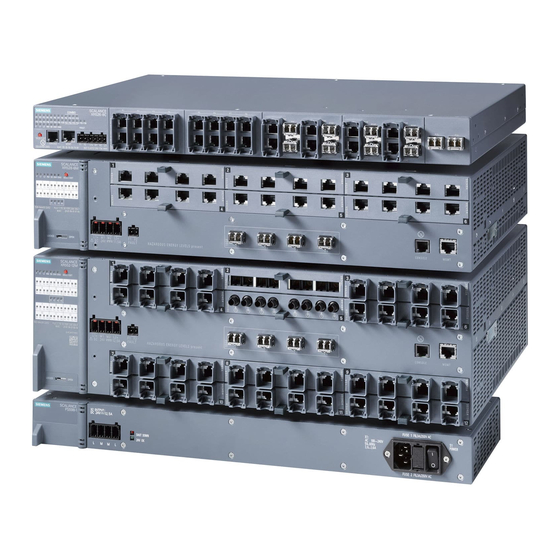
Page 19: Description Of The Device
Description of the device Product overview Article numbers Device Properties Article number Firmware version XR524-8C 1 height unit, 2 x 24 VDC, connector for the power supply on the 6GK5 524-8GS00-2AR2 as of V4.1 front, layer 3 with KEY-PLUG 1 height unit, 2 x 24 VDC, connector for the power supply on the 6GK5 524-8GR00-2AR2 as of V4.1 front, layer 3 integrated 1 height unit, 1 x 100 to 240 VAC, connector for the power supply... - Page 20 Description of the device 4.1 Product overview With the SCALANCE XR526-8C (2 x 24 VDC) if you use SFP/SFP+ pluggable transceivers in the SFP+ slots, the maximum ambient temperature is reduced to 60 °C, see section "Permitted ambient temperature (Page 98)". Interfaces Device Total usa-...
- Page 21 Description of the device 4.1 Product overview SCALANCE SCALANCE SCALANCE SCALANCE XR524-8C XR526-8C XR528-6M XR552-12M Dummy covers for the interfaces of the media module slots Labels for the slot numbers to ● ● identify the MM900 media mod- ules in use Note When the modules ship, the media module slots are fitted with dummy covers.
-
Page 22: Accessories
Description of the device 4.1 Product overview 4.1.1 Accessories Note You will find detailed information on these products in the operating instructions on the product DVD. 4.1.1.1 Accessories for the SCALANCE XR-500 product line The following accessories are available for the SCALANCE XR-500 product line: KEY-PLUG Type Article number... - Page 23 Description of the device 4.1 Product overview SFP transceiver Type Properties Article number SFP991-1 * 1 x 100 Mbps, LC port optical for glass FO cable 6GK5 991-1AD00-8AA0 (multimode), up to max. 3 km SFP991-1 (C) * 1 x 100 Mbps, LC port optical, for glass FO 6GK5 991-1AD00-8FA0 cable (multimode), up to max.
- Page 24 Description of the device 4.1 Product overview Bidirectional plug-in transceiver SFP Bidirectional plug-in transceivers feature only one fiber connection. They transmit and receive on two different wavelengths. To establish a connection, you need two matching bidirectional SFPs. The connected SFPs must respectively transmit on the wavelength at which the connection partner receives.
-
Page 25: Additional Accessories For Modular Devices
Description of the device 4.1 Product overview The following devices have SFP+ slots: ● SCALANCE XR526-8C Note Restriction with SFP+ transceivers for SCALANCE XR526-8C If you use SFP+ transceivers identified with with the SCALANCE XR526-8C, the maximum ambient temperature is reduced to 50 ℃. Note Restriction for DFP+ transceivers for SCALANCE XR526-8C (2 x 24 VDC) If you use SFP+ transceivers identified with... -
Page 26: Select/Set Button
Description of the device 4.2 SELECT/SET button Article numbers Type Properties Article number MM991-4 4 x 100 Mbps, ST ports optical, multimode fiber- 6GK5 991-4AB00-8AA0 optic cable, up to max. 5 km. MM991-4LD 4 x 100 Mbps, ST ports optical, single mode fiber- 6GK5 991-4AC00-8AA0 optic cable, up to max. - Page 27 Description of the device 4.2 SELECT/SET button Figure 4-2 SELECT/SET button on the SCALANCE XR552-12M SCALANCE XR528-6M is analogous. Setting the display mode By pressing the button briefly, you change to the display mode of the LED display. You will find detailed information on the display modes in the sections ""DM1"...
- Page 28 Description of the device 4.2 SELECT/SET button Procedure To reset the device to the factory defaults during operation, follow the steps below: 1. Switch to display mode A. Display mode A is active when the LEDs "DM1" and "DM2" are off. When the LEDs "DM1"...
-
Page 29: Led Display
Description of the device 4.3 LED display LED display 4.3.1 The "RM" LED for the "redundancy manager" function The "RM" LED indicates whether or not the device is a redundancy manager and whether or not the ring is operating free of error. LED color LED status Meaning... -
Page 30: The "F" Led For The Fault Status
Description of the device 4.3 LED display 4.3.3 The "F" LED for the fault status The "F" LED shows the fault/error status of the device. Meaning during device startup LED color LED status Meaning during device startup Device startup was completed successfully. Device startup is not yet completed or errors have occurred. -
Page 31: L1" And "L2" Leds For The Power Supply
Description of the device 4.3 LED display Setting the display mode To set the required display mode, press the "SELECT/SET" button. If you do not press the "SELECT/SET" button for longer than 1 minute, the device automatically changes to display mode A. Pressing SELECT/SET button LED status Display mode... -
Page 32: Port P1, P2
Description of the device 4.3 LED display Meaning in display mode D In display mode D, the "L1" and "L2" LEDs indicate whether the power supply is monitored. Table 4- 3 Monitoring for devices with 24 VDC L1/L2 LED L1/L2 connector LED color LED status Power supply is not monitored. - Page 33 Description of the device 4.3 LED display LED color LED status Meaning Yellow Flashing / lit Receiving data at port * 1 period ≙ 2.5 seconds Note LEDS for the SFP+ slots If SFPs are plugged into SFP+ slots of the SCALANCE XR528-6M and SCALANCE XR552- 12M the LEDs do not indicate any data transfer for these slots.
-
Page 34: C-Plug / Key-Plug
Description of the device 4.4 C-PLUG / KEY-PLUG Meaning in display mode E In display mode E, the port LEDs indicate whether the connected device is supplied using PoE. LED color LED status Meaning The connected device is not supplied using PoE. Green The connected device is supplied via PoE. - Page 35 Description of the device 4.4 C-PLUG / KEY-PLUG How it works Operating mode In terms of the C-PLUG / KEY-PLUG, there are three modes for the device: ● Without C-PLUG/KEY-PLUG The device stores the configuration in internal memory. This mode is active if no C-PLUG/KEY-PLUG is inserted. ●...
-
Page 36: Removal And Insertion Of The C-Plug/Key-Plug
Description of the device 4.4 C-PLUG / KEY-PLUG 4.4.2 Removal and insertion of the C-PLUG/KEY-PLUG NOTICE Do not remove or insert a C-PLUG/KEY-PLUG during operation A C-PLUG/KEY-PLUG may only be removed or inserted when the device is turned off. Position of the C-PLUG/KEY-PLUG with rack devices On a SCALANCE XR524-8C and SCALANCE XR526-8C, the slot is below a cover on the left-hand side of the hous- ing. -
Page 37: Combo Ports
Description of the device 4.5 Combo ports Combo ports The following devices have combo ports: ● SCALANCE XR524-8C ● SCALANCE XR526-8C Characteristics Combo port is the name for two communication ports. A combo port has the two following jacks: ● a fixed RJ-45 port ●... - Page 38 Description of the device 4.5 Combo ports SCALANCE XR-500 Operating Instructions, 09/2018, A5E03275845-12...
-
Page 39: Assembling
Assembling Safety notices for installation Safety notices When installing the device, keep to the safety notices listed below. WARNING If a device is operated in an ambient temperature of more than 50 °C, the temperature of the device housing may be higher than 70 °C. The device must therefore be installed so that it is only accessible to service personnel or users that are aware of the reason for restricted access and the required safety measures at an ambient temperature higher than 50 °C. - Page 40 Assembling 5.1 Safety notices for installation WARNING When used in hazardous environments corresponding to Class I, Division 2 or Class I, Zone 2, the device must be installed in a cabinet or a suitable enclosure. Safety notices for use according to ATEX and IECEx If you use the device under ATEX or IECEx conditions you must also keep to the following safety notices in addition to the general safety notices for protection against explosion: WARNING...
- Page 41 Assembling 5.1 Safety notices for installation WARNING If the cable or housing socket exceeds 70 °C or the branching point of the cables exceeds 60 °C, special precautions must be taken. If the equipment is operated in an air ambient in excess of 40 °C, only use cables with admitted maximum operating temperature of at least 80 ℃.
-
Page 42: Types Of Installation
Assembling 5.2 Types of installation NOTICE Warming and premature aging of the IE switch due to direct sunlight Direct sunlight can heat up the device and can lead to premature aging of the IE switch and its cabling. Provide suitable shade to protect the IE switch against direct sunlight. Note During installation and operation, keep to the installation guidelines and safety notices described in this document and in the system manuals "Industrial Ethernet / PROFINET... -
Page 43: 19" Rack Mounting
Assembling 5.3 19" rack mounting 19" rack mounting Notes on 19" rack mounting WARNING Increased ambient temperature When installed in a closed rack or a rack unit with several devices, the ambient temperature of the rack may be higher than the room temperature. Install the devices in an environment compatible with the maximum ambient temperature specified by the manufacturer. - Page 44 Assembling 5.3 19" rack mounting Note Installation secured at 4 points Where mechanical strain is liable to be high, for example when used on a ship, four-point mounting is necessary. You will find details in the sections "Four-point mounting (Page 46)" and "Mechanical stability (in operation) (Page 117)".
-
Page 45: Desktop Operation With Adhesive Feet
Assembling 5.4 Desktop operation with adhesive feet Desktop operation with adhesive feet Notes on desktop operation WARNING Maximum ambient temperature Note that several factors influence the maximum permitted ambient temperature, refer to the section “Permitted ambient temperature (Page 98)“ and “Technical data (Page 87)“. WARNING Ambient temperature for SCALANCE XR526-8C (AC 240V) The SCALANCE XR526-8C (AC 240V) devices may only be operated above an ambient... -
Page 46: Four-Point Mounting
Assembling 5.5 Four-point mounting Procedure Note The adhesive feet ship with the product. To mount the device on a desktop with the adhesive feet, follow the steps below: 1. Remove the covering foil on one side of the adhesive feet. 2. - Page 47 Assembling 5.5 Four-point mounting Bracket To install a SCALANCE XR-500 on a ship horizontally, you require special mounting brackets. You will find the design drawings for constructing the mounting brackets in the section "Mounting brackets for use on ships (Page 102)". Brackets for the SCALANCE XR524-8C and SCALANCE XR526-8C With the SCALANCE XR524-8C and SCALANCE XR526-8C you can use the same brackets.
- Page 48 Assembling 5.5 Four-point mounting Procedure Figure 5-2 Attaching the mounting bracket to a SCALANCE XR552-12M. SCALANCE XR524-8C, SCALANCE XR526-8C and SCALANCE XR528-6M are mounted in the same way. To install the device with a four-point mounting, follow the steps below: 1.
-
Page 49: Plugging And Pulling Mm900 Media Modules
Assembling 5.6 Plugging and pulling MM900 media modules Plugging and pulling MM900 media modules You can use media modules with the following devices: ● SCALANCE XR528-6M ● SCALANCE XR552-12M Notes on plugging/pulling media modules NOTICE Use only approved media modules In the module slots of the devices, use only approved media modules "MM900"... - Page 50 Assembling 5.6 Plugging and pulling MM900 media modules Slot Port A SCALANCE XR528-6M has a total of six slots and four SFP+ ports. Note Slot number In modular devices, the MM900 media modules can be assigned a slot number. The labels for the slot numbers ship with the modular devices.
- Page 51 Assembling 5.6 Plugging and pulling MM900 media modules Pulling a media module To pull a media module, follow the same steps as when plugging, but in the reverse order: 1. Pull out the handle of the media module. 2. Pull the media module out of the device slot. 3.
-
Page 52: Inserting And Removing Pluggable Transceivers (Sfp/Sfp+)
If you use SFP+ transceivers that are not approved for SIMATIC NET devices or their target systems, Siemens cannot accept any responsibility as to whether the Ethernet Switch system will function according to the specifications. Siemens can also not guarantee the compatibility and risk-free use of these components. -
Page 53: Inserting A Pluggable Transceiver (Sfp/Sfp+)
You will find the operating instructions of the pluggable transceivers here: ● On the data medium that ships with some products: – Product CD / product DVD – SIMATIC NET Manual Collection ● On the Internet pages of Siemens Industry Online Support (https://support.industry.siemens.com/cs/ww/en/view/59604783) 5.7.2 Inserting a pluggable transceiver (SFP/SFP+) Follow the steps below to insert a pluggable transceiver: 1. -
Page 54: Mounting Power Supply Units
Assembling 5.8 Mounting power supply units Procedure Follow the steps below to remove a pluggable transceiver: 1. Remove the connecting cable of the pluggable transceiver. 2. Open the clip of the pluggable trabsceiver. 3. Remove the pluggable transceiver from the pluggable transceiver slot. Note Do not use force It must be possible to remove the pluggable transceiver easily and without applying any... - Page 55 Assembling 5.8 Mounting power supply units Procedure Figure 5-4 19" rack mounting of the power supply unit To mount the PS598-1 power supply unit in a 19" rack, follow the steps below: 1. Secure the two mounting brackets with four screws each (M3 x 6 supplied with the ①...
-
Page 56: Mounting The Ps598-1 Power Supply Unit On The Rear Panel Of Modular Device
Assembling 5.8 Mounting power supply units 5.8.2 Mounting the PS598-1 power supply unit on the rear panel of modular device You can mount the PS598-1 power supply unit on the rear panel of the following devices: ● SCALANCE XR528-6M ● SCALANCE XR552-12M Procedure Figure 5-5 Rear panel mounting of the SCALANCE XR552-12M. - Page 57 Assembling 5.8 Mounting power supply units To mount the PS598-1 power supply unit on the rear panel of an IE switch, follow the steps below: ① 1. Fit the PS598-1 power supply unit and the IE switch together The two devices are equipped with positioning elements that must engage during installation and protect the plug from excessive bending strain.
- Page 58 Assembling 5.8 Mounting power supply units SCALANCE XR-500 Operating Instructions, 09/2018, A5E03275845-12...
-
Page 59: Connecting
Connecting Safety when connecting up Safety notices When connecting up the device, keep to the safety notices listed below. Safety information for devices with 24 V DC power supply Observe the following note for device variants with supply voltage 24 V DC: WARNING Operation only with safety extra-low voltage The device is designed for operation with a directly connectable safety extra-low voltage... - Page 60 Connecting 6.1 Safety when connecting up Safety notices on use in hazardous areas General safety notices relating to protection against explosion WARNING EXPLOSION HAZARD Do not connect or disconnect cables to or from the device when a flammable or combustible atmosphere is present. Safety notices when using the device according to Hazardous Locations (HazLoc) If you use the device under HazLoc conditions you must also keep to the following safety notices in addition to the general safety notices for protection against explosion:...
- Page 61 Connecting 6.1 Safety when connecting up Further notes WARNING Commissioning devices and replacement devices If you use redundancy mechanisms (HRP/MRP ring redundancy and/or redundant coupling of rings with standby), open the redundant path before you insert a new or replacement device in an operational network.
-
Page 62: 24 Vdc Power Supply
Connecting 6.2 24 VDC power supply NOTICE Failure of the data traffic due to contamination of optical plug-in connections Optical sockets and plugs are sensitive to contamination of the end face. Contamination can lead to the failure of the optical transmission network. Take the following precautions to avoid functional impairments: •... - Page 63 Connecting 6.2 24 VDC power supply ● The power supply is connected over a high resistance with the enclosure to allow an ungrounded set up. The two power inputs are non-floating. ● To wire up the power supply connector, use copper cable of the category 14 AWG - 10 AWG or cable with a cross-sectional area of 1.5 mm to 4 mm WARNING...
-
Page 64: 100 To 240 Vac Power Supply
Connecting 6.3 100 to 240 VAC power supply Figure 6-2 Position of the terminal block on a SCALANCE XR552-12M SCALANCE XR528-6M is analogous. Contact Assignment +24 VDC Ground Ground +24 VDC 100 to 240 VAC power supply 6.3.1 Power supply of the SCALANCE XR524-8C and SCALANCE XR526-8C Notes on the power supply WARNING Danger from line voltage... - Page 65 Connecting 6.3 100 to 240 VAC power supply WARNING Devices with a 100 to 240 VAC power supply do not have an ATEX or IECEx approval. Devices with a 100 to 240 V AC power supply are not approved for use in hazardous areas according to EC-RL-94/9 ATEX or IECEx.
-
Page 66: Power Supply Using The Ps598-1 Power Supply Unit
Connecting 6.3 100 to 240 VAC power supply Grounding WARNING Danger from line voltage Grounding simply via the housing is inadequate. In this case, connect the functional ground to ensure reliable operation. The grounding bolt is located on the rear panel of the device. 6.3.2 Power supply using the PS598-1 power supply unit 6.3.2.1... - Page 67 Connecting 6.3 100 to 240 VAC power supply NOTICE CAUTION/DOUBLE POLE ② The fuses FUSE1 and FUSE2 are in the fuse holder (position ). The fuses are of the type F6.3AH / 250 VAC. NOTICE Overvoltage protection for the power supply cables If there is any possible overload of the power supply cables, suitable overvoltage protection is necessary.
- Page 68 Connecting 6.3 100 to 240 VAC power supply Pin assignment of the X3 plug on the rear Connector X3 is located on the back of the PS598-1. Connector X3 is intended only to connect the PS598-1 directly to SCALANCE XR-528-6M and SCALANCE XR552-12M. Figure 6-6 Position of the plug X3 on the PS598-1 power supply unit Contact...
- Page 69 Connecting 6.3 100 to 240 VAC power supply Two PS598-1 per device, 1-out-of-2 redundancy Figure 6-8 Connecting two power supply units to a SCALANCE XR552-12M. SCALANCE XR528- 6M is used analogously. Connect the IE switch and the PS598-1 with one cable for 24 VDC and a cable for ground. As an alternative, you can also mount the two PS598-1 power supply units on the rear of the IE switch and secure them with screws.
-
Page 70: Led Display Of The Ps598-1 Power Supply Unit
Connecting 6.4 Signaling contact Connect each IE switch to its own PS598-1. In addition to this, connect both IE switches to the third PS598-1. Both IE switches devices can now continue to operate after the failure of one PS598-1. The IE switch detects the failure of a power source and signals the failure. The PS598-1 units share the applied load automatically and uniformly. - Page 71 Connecting 6.4 Signaling contact Position and assignment Figure 6-10 Position of the signaling contact on a SCALANCE XR524-8C SCALANCE XR526-8C is analogous. Figure 6-11 Position of the signaling contact on a SCALANCE XR552-12M. SCALANCE XR528-6M is analogous. Signaling faults ● The signaling of errors/faults by the signaling contact is synchronized with the fault LED "F".
-
Page 72: Serial Interface
Connecting 6.5 Serial interface Serial interface Information on the serial interface ● Via the serial interface on the device (RJ-11 jack), you can access the CLI of the device directly via an RS-232 (115200 8N1) connection without assigning an IP address. ●... -
Page 73: Out-Of-Band Interface
Connecting 6.6 Out-of-band interface Assignment of the terminal block The supplied connecting cable has the following assignment: Contact Pin assignment of the RJ-11 plug Pin assignment of the D-sub female con- nector TD (Transmit Data) TD (Transmit Data) RD (Receive Data) SG (Signal Ground) RD (Receive Data) SG (Signal Ground) - Page 74 Connecting 6.6 Out-of-band interface Position Figure 6-14 Position of the out-of-band interface on a SCALANCE XR524-8C SCALANCE XR526-8C is analogous. Figure 6-15 Position of the out-of-band interface on a SCALANCE XR552-12M. SCALANCE XR528- 6M is analogous. SCALANCE XR-500 Operating Instructions, 09/2018, A5E03275845-12...
-
Page 75: Block Architecture Of The Xr552-12M
Connecting 6.7 Block architecture of the XR552-12M Block architecture of the XR552-12M Special features of device-internal data transfer The SCALANCE XR552-12M has two switch blocks. The assignment of the ports to the two blocks A and B is shown in the graphic below: Figure 6-16 Block architecture of the SCALANCE XR552-12M Communication between the switch blocks is via two connections each operating at 13.6... - Page 76 Connecting 6.8 Functional ground Fitting grounding bolts ① Toothed washer ② Grounding bolt To fit the grounding bolt for a SCALANCE XR552-12M and SCALANCE XR528-6M, follow the steps below: ① 1. Thread the toothed washer onto the bolt. ② 2. Screw in the grounding bolt with a maximum tightening torque of 2 Nm.
-
Page 77: Uninstalling
Uninstalling Uninstalling the device 1. Remove all connectors. 2. Remove the power supply unit/units from the rear of the device. 3. When necessary release the locking mechanisms on the rack device (such as the handles on the media modules or the clip on the SFP/SFP+) to be able to remove the media modules (MM900) or the transceivers (SFP/SFP+). - Page 78 Uninstalling SCALANCE XR-500 Operating Instructions, 09/2018, A5E03275845-12...
-
Page 79: Upkeep And Maintenance
Upkeep and maintenance Changing the fan unit The following devices have a fan unit: ● SCALANCE XR528-6M ● SCALANCE XR552-12M NOTICE Operation of the SCALANCE XR-500 only with fan unit Use a SCALANCE X-500 only with a correctly fitted fan unit. Operating without the fan is not possible and would damage the device! You can, however, replace the fan unit during operation. - Page 80 Upkeep and maintenance 8.1 Changing the fan unit Procedure Follow the steps below to replace the fan unit: 1. Unlock the door in the housing by pushing the catch to the right with a slotted screwdriver ① Figure 8-1 Opening the housing of a SCALANCE XR552-12M. SCALANCE XR528-6M is used analogously.
- Page 81 Upkeep and maintenance 8.1 Changing the fan unit ④ 4. Disconnect the fan unit and the filter frame Figure 8-2 Changing the fan of a SCALANCE XR552-12M SCALANCE XR528-6M is used analogously. 5. Push the new fan unit into the slot along the guide rails. 6.
-
Page 82: Changing The Filter Pad
Upkeep and maintenance 8.2 Changing the filter pad Changing the filter pad The following devices have a filter pad: ● SCALANCE XR528-6M ● SCALANCE XR552-12M NOTICE Damage to the device due to inadequate ventilation A badly contaminated filter reduces air flow and can cause the device to be damaged. Check the degree of contamination of the filter regularly and clean or replace the filter mat as necessary. -
Page 83: Downloading New Firmware Using Tftp Without Wbm And Cli
Downloading new firmware using TFTP without WBM and CLI Firmware The firmware is signed and encrypted. This ensures that only firmware created by Siemens can be downloaded to the device. Procedure with Microsoft Windows Using TFTP, you can supply a device with new firmware even when it cannot be reached using WBM or CLI. -
Page 84: Restoring The Factory Settings
Upkeep and maintenance 8.4 Restoring the factory settings Follow the steps below to load new firmware using TFTP: 1. Turn off the power to the device. 2. Now press the "SELECT/SET" button and reconnect the power to the device while holding down the button. - Page 85 Upkeep and maintenance 8.4 Restoring the factory settings Restoring the factory settings during the startup phase NOTICE Reset despite disabled "SELECT/SET" button Using the "SELECT/SET" button, you can always reset the device parameters to the factory defaults during the startup phase of the device. This applies also if the "Reset to Factory Defaults"...
- Page 86 Upkeep and maintenance 8.4 Restoring the factory settings SCALANCE XR-500 Operating Instructions, 09/2018, A5E03275845-12...
-
Page 87: Technical Data
Technical data Technical specifications of the SCALANCE XR524-8C The following technical specifications apply to the SCALANCE XR524-8C. Technical specifications Attachment to Industrial Ethernet Electrical connectors Quantity Connector RJ-45 jack Transmission speed 10 / 100/ 1000 Mbps Slots for SFP transceivers Quantity Connector SFP transceiver... - Page 88 Technical data 9.1 Technical specifications of the SCALANCE XR524-8C Technical specifications Frequency range 47 Hz to 63 Hz Fusing 3.15 A / 250 V Current consumption at 100 VAC 0.6 A Current consumption at 240 VAC 0.37 A Effective power loss 24 W Properties Not implemented redundantly...
- Page 89 Technical data 9.1 Technical specifications of the SCALANCE XR524-8C Technical specifications Installation options 19" rack mounting • Desktop operation • Four-point mounting • Design of the mounting bracket for use on ships Dimensions without brackets for 43.6 x 43.6 x 18.3 mm (1 height unit) 19"...
-
Page 90: Technical Specifications Of The Scalance Xr526-8C
Technical data 9.2 Technical specifications of the SCALANCE XR526-8C Technical specifications of the SCALANCE XR526-8C The following technical specifications apply to the SCALANCE XR526-8C. Technical specifications Attachment to Industrial Ethernet Electrical connectors Quantity Connector RJ-45 jack Transmission speed 10 / 100/ 1000 Mbps Slots for SFP transceivers Quantity Connector... - Page 91 Technical data 9.2 Technical specifications of the SCALANCE XR526-8C Technical specifications Current consumption at 100 VAC 0.8 A Current consumption at 240 VAC 0.42 A Effective power loss 38 W Properties Not implemented redundantly 2 x 100 to 240 VAC Design IEC plug C14 with switch, 2-pin...
- Page 92 Technical data 9.2 Technical specifications of the SCALANCE XR526-8C Technical specifications Installation options 19" rack mounting • Desktop operation • Four-point mounting • Design of the mounting bracket for use on ships Dimensions without brackets for 43.6 x 43.6 x 18.3 mm (1 height unit) 19"...
-
Page 93: Technical Specifications Of The Scalance Xr528-6M
Technical data 9.3 Technical specifications of the SCALANCE XR528-6M Technical specifications of the SCALANCE XR528-6M The following technical specifications apply to the SCALANCE XR528-6M. Technical specifications Attachment to Industrial Ethernet Slots for media modules Quantity Slots for SFP transceivers (SFP+) Quantity Connector SFP transceivers (LC port) - Page 94 Technical data 9.3 Technical specifications of the SCALANCE XR528-6M Technical specifications Permitted ambient conditions Ambient temperature Operation without filter pad and with- 0 °C to +60 °C out SFP+ LH transceiver up to 2000 m When operating as of 2000 m The maximum ambient temperature is reduced by 5°C During storage...
-
Page 95: Technical Specifications Of The Scalance Xr552-12M
Technical data 9.4 Technical specifications of the SCALANCE XR552-12M Technical specifications of the SCALANCE XR552-12M The following technical specifications apply to the SCALANCE XR552-12M. Technical specifications Attachment to Industrial Ethernet Slots for media modules Quantity Slots for SFP transceivers (SFP+) Quantity Connector SFP transceivers (LC port) - Page 96 Technical data 9.4 Technical specifications of the SCALANCE XR552-12M Technical specifications Permitted ambient conditions Ambient temperature Operation without filter pad and with- 0 °C to +60 °C out SFP+ LH transceiver up to 2000 m When operating as of 2000 m The maximum ambient temperature is reduced by 5°C During storage...
-
Page 97: Switching Properties
Technical data 9.5 Switching properties Switching properties The properties listed below apply to the SCALANCE XR-500. Table 9- 1 Switching properties Max. number of learnable ad- 16 000 dresses Aging time Can be configured (default value: 40 seconds) Switching technique Store&Forward Latency 25-70 microseconds... -
Page 98: Permitted Ambient Temperature
Technical data 9.6 Permitted ambient temperature Permitted ambient temperature The maximum permitted ambient temperature of a device of the product line SCALANCE XR -500 depends on the components used. Note the information with the individual components in the section "Accessories (Page 22)" and the Technical specifications (Page 87). SCALANCE XR524-8C For SCALANCE XR524-8C (24 VDC), the ambient temperature must not exceed 70 °C. -
Page 99: Dimension Drawings
Dimension drawings 10.1 SCALANCE XR524-8C and SCALANCE XR526-8C View from front and above Dimensions are specified in mm. SCALANCE XR-500 Operating Instructions, 09/2018, A5E03275845-12... -
Page 100: Scalance Xr528-6M
Dimension drawings 10.2 SCALANCE XR528-6M 10.2 SCALANCE XR528-6M View from front and above Dimensions are specified in mm. SCALANCE XR-500 Operating Instructions, 09/2018, A5E03275845-12... -
Page 101: Scalance Xr552-12M
Dimension drawings 10.3 SCALANCE XR552-12M 10.3 SCALANCE XR552-12M View from front and above Dimensions are specified in mm. SCALANCE XR-500 Operating Instructions, 09/2018, A5E03275845-12... -
Page 102: Mounting Brackets For Use On Ships
Dimension drawings 10.4 Mounting brackets for use on ships 10.4 Mounting brackets for use on ships Introduction To install a SCALANCE XR-500 on a ship horizontally, you require special mounting brackets. Below you will find the design drawing for making the mounting brackets. You will find the more information on the construction of the mounting brackets in the section "Technical data (Page 87)". - Page 103 Dimension drawings 10.4 Mounting brackets for use on ships Brackets for the SCALANCE XR524-8C and SCALANCE XR526-8C View from the front, top, and side Dimensions are specified in mm. SCALANCE XR-500 Operating Instructions, 09/2018, A5E03275845-12...
- Page 104 Dimension drawings 10.4 Mounting brackets for use on ships Mounting bracket for a SCALANCE XR528-6M Mounting bracket left View from the front, top, and side (left) Dimensions are specified in mm. SCALANCE XR-500 Operating Instructions, 09/2018, A5E03275845-12...
- Page 105 Dimension drawings 10.4 Mounting brackets for use on ships Mounting bracket right View from the front, top, and side (right) Dimensions are specified in mm. SCALANCE XR-500 Operating Instructions, 09/2018, A5E03275845-12...
- Page 106 Dimension drawings 10.4 Mounting brackets for use on ships Mounting bracket for a SCALANCE XR552-12M Mounting bracket left View from the front, top, and side (left) Dimensions are specified in mm. SCALANCE XR-500 Operating Instructions, 09/2018, A5E03275845-12...
- Page 107 Dimension drawings 10.4 Mounting brackets for use on ships Mounting bracket right View from the front, top, and side (right) Dimensions are specified in mm. SCALANCE XR-500 Operating Instructions, 09/2018, A5E03275845-12...
- Page 108 Dimension drawings 10.4 Mounting brackets for use on ships SCALANCE XR-500 Operating Instructions, 09/2018, A5E03275845-12...
-
Page 109: Certification
You can check which of the following approvals have been granted for your product by the markings on the type plate. Current approvals on the Internet You will find the current approvals for the product on the Internet pages of Siemens Industry Online Support (https://support.industry.siemens.com/cs/ww/en/ps/15312/cert). Notes for the manufacturers of machines The devices are not machines in the sense of the EC Machinery Directive. - Page 110 EC L174, 01/07/2011, p. 88-110 You will find the EC declaration of conformity for these products on the Internet pages of Siemens Industry Online Support (https://support.industry.siemens.com/cs/ww/en/ps/15273/cert). The EC Declaration of Conformity is available for all responsible authorities at:...
- Page 111 • On the data medium that ships with some products: – Product CD / product DVD – SIMATIC NET Manual Collection • On the Internet pages of Siemens Industry Online Support (https://support.industry.siemens.com/cs/ww/en/view/78381013) The SIMATIC NET products described in these operating instructions meet the requirements of the EU directive 2014/34/EU "Equipment and Protective Devices for Use in Potentially...
- Page 112 Certification ● nA [op is] ATEX classification: II 3 (2) G Ex nA [op is Gb] IIC T4 Gc Certificate no.: DEKRA 11ATEX0060 X The products meet the requirements of the following standards: – EN 60079-28 (Explosive atmospheres - Part 28: Protection of equipment and transmission systems using with optical radiation) –...
- Page 113 Certification Permitted types of protection The following types of protection are possible: ● nA IECEx classification: Ex nA IIC T4 Gc Certificate no.: DEK 14.0025X The products meet the requirements of the following standards: – IEC 60079-15 (Explosive atmospheres - Part 15: Equipment protection by type of protection "n") –...
- Page 114 Certification Note for devices with CLASS 1 LASER Important note on products certified according to Type Examination Certificate KEMA 07ATEX0145 X as of Issue 95 / DEKRA 18ATEX0025X and IECEx Certificate of Conformity DEK 14.0025X as of Issue 43 / DEK 18.0017X and containing Class 1 optical radiation sources.
- Page 115 Certification RoHS The SIMATIC NET products described in these operating instructions meet the requirements of the EC directive 2011/65/EC for the restriction of the use of certain hazardous substances in electrical and electronic equipment: Applied standard: ● EN 50581 The product meets the requirements of the standards: ●...
- Page 116 Certification cULus Approval Hazardous Location cULus Listed I. T. E. FOR HAZ. LOC. Underwriters Laboratories Inc. complying with ● UL 60950-1 (Information Technology Equipment) ● ANSI/ISA 12.12.01-2007 ● CSA C22.2 No. 213-M1987 Approved for use in Cl. 1, Div. 2, GP A, B, C, D T4 Cl.
- Page 117 Certification 11.1 Mechanical stability (in operation) FDA and IEC marking The following devices meet the FDA and IEC requirements listed below: Device CLASS 1 LASER Product SCALANCE XR524-8C SCALANCE XR526-8C SCALANCE XR528-6M SCALANCE XR552-12M * For modular devices, you can find the marking in the operating instructions for the media module or plug-in transceiver used.
- Page 118 ● "Industrial Ethernet / PROFINET Industrial Ethernet" System Manual (https://support.industry.siemens.com/cs/ww/en/view/27069465) ● "Industrial Ethernet / PROFINET - Passive Network Components" System Manual (https://support.industry.siemens.com/cs/ww/en/view/84922825) ● "EMC Installation Guidelines" configuration manual (https://support.industry.siemens.com/cs/ww/en/view/60612658)
-
Page 119: Index
Index Factory settings, 49, 85 Fan unit, 20, 25, 79 Fault/error status, 30, 71 Filter frame, 20, 80, 83 19" rack mounting, 42, 43 Filter pad, 20, 80, 82 Firmware, 30, 83 Four-point mounting, 42, 44, 46 Front terminal, 45 Accessories, 22 Functional ground, 75 Adhesive foot, 20, 46... - Page 120 Index System manual, 6, 42, 118 Operating mode, 33 Operating temperature, 41 Out-of-band interface, 73, 84 Overvoltage protection, 62, 67 Tensile strain relief, 45 Terminal block, 20, 62, 70 Transmission speed, 33 Type designation, 21 Type of installation, 42 PLUG, 34 Pluggable transceiver, 20 Inserting, 53 Notes on deinstallation, 53...