Toro 68141 Operator's Manual
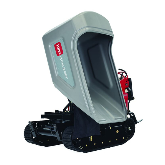
Tracked mud buggy
Hide thumbs
Also See for 68141:
- Operator's manual (44 pages) ,
- Operator's manual (64 pages) ,
- Operator's manual (44 pages)

Related Manuals for Toro 68141


Summary of Contents for Toro 68141
- Page 1 Operator’s Manual MB TX 2500S Tracked Mud Buggy Model—Serial Range 68141—400000000 and Up 68141G—400000000 and Up *3451-708* A 3451-708A Original Instructions (EN)
-
Page 2: Table Of Contents
Because in some areas there are local, state, or federal regulations requiring that a spark arrester be used on the engine of this machine, a spark arrester is available as an option. If you require a spark arrester, contact your Authorized Service Dealer. Genuine Toro spark arresters are approved by the USDA Forestry Service. -
Page 3: Disclaimers And Regulatory Information
Parking Brake..........................3–3 Throttle Control ..........................3–3 Specifications ............................ 3–3 Attachments/Accessories....................... 3–4 Chapter 4: Operation ........................... 4–1 Before Operation ..........................4–1 Before Operation Safety ......................4–1 Fuel ..............................4–2 Performing Daily Maintenance ....................4–3 During Operation ..........................4–3 During Operation Safety ......................4–3 Starting the Engine........................ - Page 4 Hydraulic Drive System......................5–23 Hydraulic Lift and Slew System....................5–26 Checking the Hydraulic Lines ....................5–29 Cleaning............................5–30 Removing Debris ........................5–30 Chapter 6: Storage..........................6–1 Storage Safety ..........................6–1 Preparing the Machine for Storage Over 30 Days..............6–1 Chapter 7: Troubleshooting ....................... 7–1 Chapter 8: California Proposition 65 Warning Information ............
-
Page 5: Chapter 1: Introduction
Whenever you need service, genuine Toro parts, or additional information, contact an Authorized Service Dealer or Toro Customer Service and have the model and serial numbers of your product ready. These numbers are located on the serial plate on your product . -
Page 6: Manual Conventions
Manual Conventions This manual identifies potential hazards and has safety messages identified by the safety- alert symbol, which signals a hazard that may cause serious injury or death if you do not follow the recommended precautions. G405934 This manual uses 2 words to highlight information. Important calls attention to special mechanical information and Note emphasizes general information worthy of special attention. -
Page 7: Chapter 2: Safety
Chapter 2 Safety General Safety • Read and understand the contents of this Operator’s Manual before starting the engine. • Do not operate the machine without all guards and other safety protective devices in place and functioning properly on the machine. •... - Page 8 Decal Part: 125-4967 Lift point decal125-4967 Decal Part: 132-8961 Battery charging condition Hour meter Hopper is raising. Hopper is lowering. Hopper is down. Hopper is lowering automatically. decal132-8961 Decal Part: 133-8062 s_decal133-8062 Decal Part: 132-9051 Tie-down point decal132-9051 Safety: Safety and Instructional Decals Page 2–2 3451-708 A...
- Page 9 Decal Part: 132-9052 Power Auxiliary Logic decal132-9052 Decal Part: 137-0575 Read the Operator’s Manual. Transmission fluid Cold fill line decal137-0575 Decal Part: 139-7223 decal139-7223 Read the Operator’s Manual. 3451-708A Page 2–3 Safety: Safety and Instructional Decals...
- Page 10 Decal Part: 139-7202 decal139-7202 Warning—keep bystanders away; look behind and Parking brake—disengage down when moving in reverse. Parking brake—engage Warning—engage the parking brake, shut off the Warning—read the Operator’s Manual; wear engine, and remove the key before leaving the hearing protection. operator’s position.
-
Page 11: Chapter 3: Product Overview
Chapter 3 Product Overview Hopper Hood Control panel Fuel-tank cap Operator platform Tracks g038268 Controls Choke Control the choke before starting a NGAGE cold engine. the choke when the ISENGAGE engine is warm. G376191 3451-708 A Page 3–1 Product Overview... -
Page 12: Drive Controls
Drive Controls G375673 Dump Controls Dump hopper Lower hopper G375675 Swivel Switch Swivel left Swivel right G375676 Product Overview: Controls Page 3–2 3451-708 A... -
Page 13: Key Switch
Key Switch Stop engine Run engine Start engine G375755 Parking Brake Engage Disengage g009465 Throttle Control g357324 Specifications Note: Specifications and design are subject to change without notice. Width 90.2 cm (35.5 inches) Length 268 cm (105.5 inches) Height 130.18 cm (51.25 inches) Weight 855.5 kg (1886 lb) Hopper capacity... -
Page 14: Attachments/Accessories
Attachments/Accessories A selection of Toro approved attachments and accessories is available for use with the machine to enhance and expand its capabilities. Contact your Authorized Service Dealer or authorized Toro distributor or go to www.Toro.com for a list of all approved attachments and accessories. -
Page 15: Chapter 4: Operation
Chapter 4 Operation Before Operation Before Operation Safety General Safety • Never allow children or untrained people to operate the machine. Local regulations may restrict the age of the operator. The owner is responsible for training all operators and mechanics. •... -
Page 16: Fuel
Before Operation Safety (continued) • If you spill fuel, do not attempt to start the engine; avoid creating any source of ignition until the fuel vapors have dissipated. • Do not fill containers inside a vehicle or on a truck or trailer bed with a plastic liner. Always place containers on the ground, away from your vehicle before filling. -
Page 17: Performing Daily Maintenance
Fuel (continued) Filling the Fuel Tank 1. Clean the area around the fuel-tank cap. 2. Remove the cap. 3. Add fuel until it is at the bottom of the filler neck. Note: Do not fill the fuel tank completely full. The empty space in the tank allows the fuel to expand. - Page 18 During Operation Safety (continued) • Never jerk the controls; use a steady motion. • Use care when approaching blind corners, shrubs, trees, or other objects that may obscure your vision. • Slow down and use caution when making turns and crossing roads and sidewalks with the machine.
-
Page 19: Starting The Engine
During Operation Safety (continued) • Operate up and down slopes with the heavy end of the machine uphill. Weight distribution changes with a full hopper. A full hopper makes the front of the machine the heavy end, so walk behind the machine with the full hopper uphill. •... -
Page 20: Shutting Off The Engine
Starting the Engine (continued) 5. When the engine starts , disengage the choke IMPORTANT Do not engage the starter for more than 5 seconds at a time. If the engine fails to start, allow a 15-second cool-down period between attempts. Failure to follow these instructions can burn out the starter. -
Page 21: Operating The Hopper
Operator Platform (continued) • When loading or unloading the machine from a trailer for transport • Driving up slopes Operate the machine with the platform down for the following conditions: • Using the machine in most areas • Driving across slopes •... -
Page 22: After Operation
Operating the Hopper (continued) 1. Position the machine where you intend to dump the load. 2. Rotate the hopper left or right by pushing the left or right side of the swivel switch 3. Dump the hopper by pushing the top of the dump switch 4. -
Page 23: Lowering The Hopper Without Power
Removing Debris from the Machine (continued) 5. Wipe away debris from the air cleaner. 6. Clean any debris buildup on the engine and in the transmission with a brush or blower. IMPORTANT Blow out dirt rather than wash it out. If you use water, keep it away from electrical parts and hydraulic valves. -
Page 24: Raising The Hopper Without Power
Lowering the Hopper without Power (continued) 5. Disconnect the hose fittings in the manifold block and allow the fluid to drain into the pan. Note: Dispose of the used fluid at a certified recycling center. 6. Connect the hose fittings. 7. -
Page 25: Haul The Machine
Raising the Hopper without Power (continued) 5. Disconnect the hose fittings in the manifold block and allow the fluid to drain into the pan. Note: Dispose of the used fluid at a certified recycling center. 6. Use a hoist or have 2 people hold up the hopper and install the cylinder lock. - Page 26 Haul the Machine (continued) Full-width ramp in stowed position Ramp is at least 4 times as long as the height of the trailer or truck bed to the ground H = height of the trailer or truck bed to the ground Trailer G229507 Loading the Machine...
- Page 27 Haul the Machine (continued) 6. Use the metal tie-down loop to securely fasten the machine to the trailer or truck with straps, chains, cable, or ropes . Refer to local regulations for tie-down requirements. G376092 IMPORTANT Do not use the tie-down loops to lift the machine. Unloading the Machine 1.
-
Page 28: Chapter 5: Maintenance
• Use the cylinder lock to secure the hopper in the raised position. • Never tamper with safety devices. • To ensure safe, optimal performance of the machine, use only genuine Toro replacement parts. Replacement parts made by other manufacturers could be dangerous, and such use could void the product warranty. -
Page 29: Recommended Maintenance Schedule
Check the road wheels. Replace the spark plug. Replace the drive belt. 139-1295 Belt Change the hydraulic fluid for the Toro premium transmission/ 108-1184 Every 300 hours drive system. hydraulic fluid Change the hydraulic fluid for the Toro hypr-oil 500 114-4714 lift and slew system. -
Page 30: Pre-Maintenance Procedures
Maintenance Qty Description Maintenance Procedure Part No. Service Interval Change the hydraulic filter for the 1-633750 Filter lift and slew system. Pre-Maintenance Procedures Moving a Non-Functional Machine IMPORTANT Do not tow or pull the machine without first opening the bypass valves in this procedure, or you will damage the hydraulic system. -
Page 31: Releasing The Cushion For Rear Access
Lifting the Machine (continued) 1. Place the platform in the raised position. 2. Rotate the hopper and hoist the machine using the lifting points. Note: Take up the slack in the chain or straps to properly balance the unit. G324717 Releasing the Cushion for Rear Access 1. -
Page 32: Lubrication
Using the Cylinder Lock (continued) 3. Slide the cylinder lock over the lift-cylinder rod and secure with the cotterless pins. G324856 Removing and Storing the Cylinder Lock IMPORTANT Remove the cylinder lock from the lift-cylinder rod and fully secure it in the storage position before operating the machine. -
Page 33: Engine Maintenance
Greasing the Machine (continued) 4. Connect a grease gun to each fitting. G376193 5. Pump grease into the fittings until grease begins to ooze out of the bearings (approximately 3 pumps). 6. Wipe up any excess grease. Engine Maintenance Servicing the Air Cleaner IMPORTANT Do not operate the engine without the air-cleaner element. -
Page 34: Engine Oil Service
Servicing the Air Cleaner (continued) 1. Rotate the latches outward. 2. Remove the cover to access the air-cleaner elements. 3. Remove the cover to access the air-cleaner elements. 4. Remove the foam element from the paper element 5. Service the foam element A. - Page 35 Engine Oil Service (continued) g017552 Checking the Engine-Oil Level G376333 1. Park the machine on a level surface, move the motion-control levers to the N EUTRAL LOCK position, engage the parking brake, and lower the hopper. 2. Shut off the engine, and remove the key. Allow the engine to cool. 3.
-
Page 36: Replacing The Spark Plug
Engine Oil Service (continued) Changing the Engine Oil and Filter 1. Park the machine on a level surface, move the motion-control levers to the N EUTRAL LOCK position, engage the parking brake, raise the hopper, and install the cylinder lock. 2. -
Page 37: Cleaning The Blower Housing
Replacing the Spark Plug (continued) 2. Clean around spark plug and remove plug from cylinder head. Note: Replace a cracked, fouled, or dirty spark plug. Do not sand blast, scrape, or clean electrodes because engine damaged could result from grit entering the cylinder. 3. -
Page 38: Fuel System Maintenance
Fuel System Maintenance Replacing the Fuel Filter G376153 1. Park the machine on a level surface, move the motion-control levers to the N EUTRAL LOCK position, engage the parking brake, and lower the hopper. 2. Shut off the engine, and remove the key. Allow the engine to cool. 3. -
Page 39: Removing The Fuel Tank
Removing the Fuel Tank 1. Lower the platform. 2. Release the cushion. 3. Remove the cross bracket 4. Remove the fuel tank and set it on the operator platform. Note: Remove the fuel and vent lines from the top of the tank to move the fuel tank further from the machine. - Page 40 Battery Service (continued) Charging the Battery WARNING Charging the battery produces gasses that can explode. Never smoke near the battery and keep sparks and flames away from battery. IMPORTANT Always keep the battery fully charged (1.265 specific gravity). This is especially important to prevent battery damage when the temperature is below 0°C (32°F).
-
Page 41: Replacing A Fuse
Battery Service (continued) 4. Charge the battery for 1 hour at 25 to 30 A or 6 hours at 4 to 6 A. IMPORTANT Do not overcharge the battery. Positive battery post Negative battery post Red (+) charger lead Black (-) charger lead g003792 5. -
Page 42: Drive System Maintenance
Replacing a Fuse (continued) Main power fuse (15 A) Auxiliary power fuse (15 A) Logic fuse (7.5 A) G376375 1. Release the cushion from the rear of the machine. 2. Pull out the fuse to remove or replace it. 3. Install the cushion to the rear of the machine. Note: Ensure that the correct-size fuse is installed. - Page 43 Track Service (continued) 4. Using a water hose or pressure washer, remove dirt from each track system. IMPORTANT Ensure that you use high-pressure water to wash only the track area. Do not use a high-pressure washer to clean the rest of the machine. Do not use high-pressure water between the drive sprocket and the machine or you may damage the motor seals.
- Page 44 Track Service (continued) 2. Shut off the engine, and remove the key. Allow the engine to cool. 3. Clean the tracks with high-pressure water. IMPORTANT Ensure that you use high-pressure water to wash only the track area. Do not use a high-pressure washer to clean the rest of the machine.
-
Page 45: Drive Belt
Track Service (continued) 4. Remove the retaining bolt for the tensioning screw. Front wheel Track Tensioning screw and retaining bolt Road wheel Drive sprocket g186008 5. Release the drive tension by turning the tensioning screw clockwise. 6. Remove the track at the top of the front wheel, peeling it off the wheel while rotating the track forward. - Page 46 Drive Belt (continued) 2. Shut off the engine, and remove the key. Allow the engine to cool. 3. Release the cushion and remove the fuel tank. 4. Inspect the belt. Replace the belt if it is worn. Note: The signs of a worn belt include squealing while the belt is rotating, frayed edges, burn marks, and cracks on the belt.
- Page 47 Drive Belt (continued) 7. Remove the 2 bolts and 2 nuts and loosen the 2 set screws on the coupler. Remove the gear pump from the pump mount. Note: You do not need to remove the fittings from the pump. Bolt (2) Pump mount Gear pump...
-
Page 48: Controls Maintenance
Controls Maintenance Adjusting the Motion-Control Levers If the motion-control levers do not align horizontally, adjust the right side motion-control lever. 1. Park the machine on a level surface, lower the hopper, engage the parking brake, shut off the engine, and remove the key. 2. -
Page 49: Brake Maintenance
Brake Maintenance Checking the Parking Brake 1. Park the machine on a level surface, lower the hopper, and engage the parking brake. 2. Start the engine and move the throttle lever to the F position. 3. Move the motion-control levers forward. The machine should not move forward. -
Page 50: Hydraulic System Maintenance
• Toro PX Extended Life Hydraulic Fluid (refer to your Authorized Service Dealer for more information) • If either of the above Toro fluids are not available, you may use another Universal Tractor Hydraulic Fluid (UTHF), but they must be only conventional, petroleum- based products. - Page 51 Hydraulic Drive System (continued) Checking the Hydraulic-Fluid Level for the Drive System 1. Park the machine on a level surface, move the motion-control levers to the N EUTRAL LOCK position, engage the parking brake, and lower the hopper. 2. Shut off the engine, and remove the key. Allow the engine to cool.
- Page 52 Hydraulic Drive System (continued) Changing the Hydraulic Fluid and Filter for the Drive System 1. Park the machine on a level surface, move the motion-control levers to the N EUTRAL LOCK position, engage the parking brake, and lower the hopper. 2.
-
Page 53: Hydraulic Lift And Slew System
Mobil® 424 Hydraulic Fluid Hydraulic fluid capacity: 6.6 L (1.75 US gallons) Use only 1 of the following fluids in the hydraulic system: • Toro Premium Transmission/Hydraulic Tractor Fluid (refer to your Authorized Service Dealer for more information) 3451-708A Page 5–26... - Page 54 • Toro PX Extended Life Hydraulic Fluid (refer to your Authorized Service Dealer for more information) • If either of the above Toro fluids are not available, you may use another Universal Tractor Hydraulic Fluid (UTHF), but they must be only conventional, petroleum- based products.
- Page 55 Hydraulic Lift and Slew System (continued) 6. Install the dipstick and cap onto the filler neck. 7. Wipe up any spilled hydraulic fluid. 8. Remove the cylinder lock and lower the hopper. Changing the Hydraulic Fluid for the Lift and Slew System 1.
-
Page 56: Checking The Hydraulic Lines
Hydraulic Lift and Slew System (continued) 1. Park the machine on a level surface, move the motion-control levers to the N EUTRAL LOCK position, engage the parking brake, raise the hopper, and install the cylinder lock. 2. Shut off the engine, and remove the key. Allow the engine to cool. -
Page 57: Cleaning
Cleaning Removing Debris IMPORTANT Operating the engine with blocked screens, dirty or plugged cooling fins, and/or cooling shrouds removed, will result in engine damage from overheating. 1. Park the machine on a level surface and shut off the engine. Allow the engine to cool. 2. -
Page 58: Chapter 6: Storage
Chapter 6 Storage Storage Safety • Shut off the engine, remove the key (if applicable), wait for all moving parts to stop, and allow the machine to cool before storing it. • Do not store the machine or fuel near flames. Preparing the Machine for Storage Over 30 Days 1. - Page 59 7. Prepare the fuel system. A. Add a petroleum-based fuel stabilizer/conditioner to the fuel in the tank. Do not use an alcohol-based stabilizer (ethanol or methanol). B. Run the engine to distribute conditioned fuel through the fuel system for 5 minutes. C.
-
Page 60: Chapter 7: Troubleshooting
Chapter 7 Troubleshooting The engine loses power. Possible Cause Corrective Action The engine load is excessive. Reduce the ground speed. The air cleaner is dirty. Service the air-cleaner element. The oil level in the crankcase is low. Add oil to the crankcase. The cooling fins and air passages under the Remove the obstruction from the cooling engine blower housing are plugged. - Page 61 The engine overheats. Possible Cause Corrective Action The engine load is excessive. Reduce the ground speed. The oil level in the crankcase is low. Add oil to the crankcase. The cooling fins and air passages under the Remove the obstruction from the cooling engine blower housing are plugged.
-
Page 62: Chapter 8: California Proposition 65 Warning Information
Chapter 8 California Proposition 65 Warning Information What is this warning? You may see a product for sale that has a warning label like the following: WARNING: Cancer and Reproductive Harm—www.p65Warnings.ca.gov. What is Prop 65? Prop 65 applies to any company operating in California, selling products in California, or manufacturing products that may be sold in or brought into California. - Page 63 While the exposure from Toro products may be negligible or well within the “no significant risk” range, out of an abundance of caution, Toro has elected to provide the Prop 65 warnings. Moreover, if Toro does not provide these warnings, it could be sued by the State of California or by private parties seeking to enforce Prop 65 and subject to substantial penalties.